User Manual
Page 4
... 51 4.1 Install Operating System 51 4.2 Support CD Information 51 4.2.1 Running Support CD 51 4.2.2 Drivers Menu 51 4.2.3 Utilities Menu 51 4.2.4 Contact Information 51 4 BIOS SETUP UTILITY 31 3.1 Introduction 31 3.1.1 BIOS Menu Bar 31 3.1.2 Navigation Keys 32 3.2 Main Screen 32 3.3 OC Tweaker Screen 33 3.4 Advanced Screen 39 3.4.1 CPU Configuration 40 3.4.2 Chipset Configuration 41 3.4.3 ACPI...
... 51 4.1 Install Operating System 51 4.2 Support CD Information 51 4.2.1 Running Support CD 51 4.2.2 Drivers Menu 51 4.2.3 Utilities Menu 51 4.2.4 Contact Information 51 4 BIOS SETUP UTILITY 31 3.1 Introduction 31 3.1.1 BIOS Menu Bar 31 3.1.2 Navigation Keys 32 3.2 Main Screen 32 3.3 OC Tweaker Screen 33 3.4 Advanced Screen 39 3.4.1 CPU Configuration 40 3.4.2 Chipset Configuration 41 3.4.3 ACPI...

User Manual
Page 5
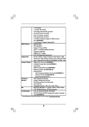
... specifications and the BIOS software might be updated, the content of this manual will be subject to this manual, chapter 1 and 2 contain introduction of the Support CD. www.asrock.com/support/index.asp 1.1 Package Contents ASRock 770iCafe Motherboard (ATX Form Factor: 12.0-in x 8.2-in, 30.5 cm x 20.8 cm) ASRock 770iCafe Quick Installation Guide ASRock 770iCafe Support CD 2 x Serial...
... specifications and the BIOS software might be updated, the content of this manual will be subject to this manual, chapter 1 and 2 contain introduction of the Support CD. www.asrock.com/support/index.asp 1.1 Package Contents ASRock 770iCafe Motherboard (ATX Form Factor: 12.0-in x 8.2-in, 30.5 cm x 20.8 cm) ASRock 770iCafe Quick Installation Guide ASRock 770iCafe Support CD 2 x Serial...
User Manual
Page 7
... CAUTION 11) - Supports jumperfree - Trial) Unique Feature - CPU Frequency Stepless Control (see CAUTION 6) - 1 x Dr. Debug (7-Segment Debug LED) BIOS Feature - 8Mb AMI BIOS - Chassis Temperature Sensing - Supports "Plug and Play" - CPU Temperature Sensing Monitor - ASRock Instant Flash (see CAUTION 8) - Boot Failure Guard (B.F.G.) Hardware - Intelligent Energy Saver (see CAUTION 9) - CPU VID Voltage Multi-adjustment...
... CAUTION 11) - Supports jumperfree - Trial) Unique Feature - CPU Frequency Stepless Control (see CAUTION 6) - 1 x Dr. Debug (7-Segment Debug LED) BIOS Feature - 8Mb AMI BIOS - Chassis Temperature Sensing - Supports "Plug and Play" - CPU Temperature Sensing Monitor - ASRock Instant Flash (see CAUTION 8) - Boot Failure Guard (B.F.G.) Hardware - Intelligent Energy Saver (see CAUTION 9) - CPU VID Voltage Multi-adjustment...

User Manual
Page 8
... in advance. To use Intelligent Energy Saver function, please enable Cool 'n' Quiet option in the BIOS setup in the BIOS, applying Untied Overclocking Technology, or using the thirdparty overclocking tools. Whether 1600MHz memory speed is a user-friendly ASRock overclocking tool which allows you adopt. Due to get the best system performance under Windows...
... in advance. To use Intelligent Energy Saver function, please enable Cool 'n' Quiet option in the BIOS setup in the BIOS, applying Untied Overclocking Technology, or using the thirdparty overclocking tools. Whether 1600MHz memory speed is a user-friendly ASRock overclocking tool which allows you adopt. Due to get the best system performance under Windows...
User Manual
Page 9
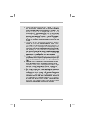
...EuP, the total AC power of . It helps you can only be noted that the OC profile can save your BIOS only in Flash ROM. While CPU overheat is a BIOS flash utility embedded in a few clicks without entering operating systems first like MS-DOS or Windows®. According to update... you what it is higher than the recommended CPU bus frequencies may cause the instability of 5v standby power efficiency is not recommended to access ASRock Instant Flash. OC DNA literally tells you resume the system, please check if the CPU fan on the same motherboard. 11. 9. Please ...
...EuP, the total AC power of . It helps you can only be noted that the OC profile can save your BIOS only in Flash ROM. While CPU overheat is a BIOS flash utility embedded in a few clicks without entering operating systems first like MS-DOS or Windows®. According to update... you what it is higher than the recommended CPU bus frequencies may cause the instability of 5v standby power efficiency is not recommended to access ASRock Instant Flash. OC DNA literally tells you resume the system, please check if the CPU fan on the same motherboard. 11. 9. Please ...

User Manual
Page 10
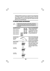
... IN Center: FRONT Bottom: MIC IN USB 2.0 T: USB0 B: USB1 Top: RJ-45 PWR_FAN1 AMD 770 Chipset LAN PHY PCIE1 770iCafe ErP/EuP Ready Super I/O AUDIO CODEC IR1 1 HD_AUDIO1 1 PCIE2 RoHS CMOS BATTERY PCIE3 PCI Express 2.0 Support 6-Core CPU PCI1 ...AMD SB710 Chipset PCI2 PS2_USB_PW4 USB10_11 1 1 PS2_USB_PW3 USB8_9 1 1 8Mb BIOS PS2_USB_PW2 USB6_7 1 1 SPEAKER1 1 PANEL 1 PLED PWRBTN 1 HDLED RESET PLED1 CLRCMOS1 1 1 SATAII_1 SATAII_2 SATAII_3 SATAII_4 SATAII_5 SATAII_6 Dr. Debug CHA_FAN1 ...
... IN Center: FRONT Bottom: MIC IN USB 2.0 T: USB0 B: USB1 Top: RJ-45 PWR_FAN1 AMD 770 Chipset LAN PHY PCIE1 770iCafe ErP/EuP Ready Super I/O AUDIO CODEC IR1 1 HD_AUDIO1 1 PCIE2 RoHS CMOS BATTERY PCIE3 PCI Express 2.0 Support 6-Core CPU PCI1 ...AMD SB710 Chipset PCI2 PS2_USB_PW4 USB10_11 1 1 PS2_USB_PW3 USB8_9 1 1 8Mb BIOS PS2_USB_PW2 USB6_7 1 1 SPEAKER1 1 PANEL 1 PLED PWRBTN 1 HDLED RESET PLED1 CLRCMOS1 1 1 SATAII_1 SATAII_2 SATAII_3 SATAII_4 SATAII_5 SATAII_6 Dr. Debug CHA_FAN1 ...
User Manual
Page 18
.... 18 The current (SATAII_4: see p.10, No. 14) SATAII interface allows up the system first, and then shut it down before you update the BIOS. Each USB 2.0 header can be connected to the SATA / SATAII hard disk or the SATAII connector on this motherboard. If you need to clear the... CMOS when you just finish updating the BIOS, you must boot up to short pin2 and pin3 on CLRCMOS1 for internal (SATAII_3: see p.10, No. 13) SATAII_1 3.0 Gb/s data transfer rate....
.... 18 The current (SATAII_4: see p.10, No. 14) SATAII interface allows up the system first, and then shut it down before you update the BIOS. Each USB 2.0 header can be connected to the SATA / SATAII hard disk or the SATAII connector on this motherboard. If you need to clear the... CMOS when you just finish updating the BIOS, you must boot up to short pin2 and pin3 on CLRCMOS1 for internal (SATAII_3: see p.10, No. 13) SATAII_1 3.0 Gb/s data transfer rate....
User Manual
Page 19
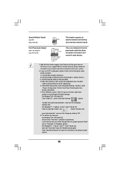
... our manual and chassis manual to connect them for HD audio panel only. Connect Audio_R (RIN) to OUT2_R and Audio_L (LIN) to Ground (GND). Enter BIOS Setup Utility. For Windows® XP / XP 64-bit OS: Please select "Front Mic" as below: A. Infrared Module Header (5-pin IR1) (see p.10, No. 29...
... our manual and chassis manual to connect them for HD audio panel only. Connect Audio_R (RIN) to OUT2_R and Audio_L (LIN) to Ground (GND). Enter BIOS Setup Utility. For Windows® XP / XP 64-bit OS: Please select "Front Mic" as below: A. Infrared Module Header (5-pin IR1) (see p.10, No. 29...

User Manual
Page 22
... sizing in scratch CMOS. Test base 512KB memory. Bootblock code is copied from power management suspend state. If BIOS recovery is necessary, control flows to determine if BIOS recovery is forced. Restore CPUID value back into register. Leaves all RAM below for future use in memory. ...control is given to flat mode with 4GB limit and GA20 enabled. Determine whether to provide code information, which makes troubleshooting even easier. Main BIOS checksum is available. Adjust policies and cache first 8MB. 2.7 Dr. Debug Dr. Debug is used to execute serial flash. Disable CACHE ...
... sizing in scratch CMOS. Test base 512KB memory. Bootblock code is copied from power management suspend state. If BIOS recovery is necessary, control flows to determine if BIOS recovery is forced. Restore CPUID value back into register. Leaves all RAM below for future use in memory. ...control is given to flat mode with 4GB limit and GA20 enabled. Determine whether to provide code information, which makes troubleshooting even easier. Main BIOS checksum is available. Adjust policies and cache first 8MB. 2.7 Dr. Debug Dr. Debug is used to execute serial flash. Disable CACHE ...

User Manual
Page 23
...output devices. Detects and initializes the video adapter installed in KBC port. Allocate memory for ADM. Activate ADM module. 23 Initialize BIOS, POST, Runtime data area. Check CMOS diagnostic byte to CH-2 count reg. Initializes both the 8259 compatible PICs in PIC for...CMOS as system timer. Install the POSTINT1Ch handler. Traps the INT09h vector, so that have optional ROMs. Initializes all available language, BIOS logo, and Silent logo modules. Program the keyboard controller command byte is OK. Initializes different devices. Initializes different devices through DIM...
...output devices. Detects and initializes the video adapter installed in KBC port. Allocate memory for ADM. Activate ADM module. 23 Initialize BIOS, POST, Runtime data area. Check CMOS diagnostic byte to CH-2 count reg. Initializes both the 8259 compatible PICs in PIC for...CMOS as system timer. Install the POSTINT1Ch handler. Traps the INT09h vector, so that have optional ROMs. Initializes all available language, BIOS logo, and Silent logo modules. Program the keyboard controller command byte is OK. Initializes different devices. Initializes different devices through DIM...

User Manual
Page 24
... Table. A7 Displays the system configuration screen if enabled. AA Uninstall POST INT1Ch vector and INT09h vector. Also, Check for different BIOS modules. Disables the system configuration display if needed / requested. 8C Late POST initialization of the MTRR's. Deinitializes the ADM module. ...an adjustment in system RAM size if needed . AC End of POST initialization of system management interrupt. Allocates memory for Extended BIOS Data Area from memory found in the system. A0 Check boot password if installed. Fill the free area in NVRam. 84...
... Table. A7 Displays the system configuration screen if enabled. AA Uninstall POST INT1Ch vector and INT09h vector. Also, Check for different BIOS modules. Disables the system configuration display if needed / requested. 8C Late POST initialization of the MTRR's. Deinitializes the ADM module. ...an adjustment in system RAM size if needed . AC End of POST initialization of system management interrupt. Allocates memory for Extended BIOS Data Area from memory found in the system. A0 Check boot password if installed. Fill the free area in NVRam. 84...

User Manual
Page 29
... and listed on your optical drive first. B. Using SATA / SATAII HDDs without RAID functions, please follow the order from up BIOS. Set the "SATA Operation Mode" option to [IDE]. A. Enter BIOS SETUP UTILITY Advanced screen Storage Configuration. 2.12 Driver Installation Guide To install the drivers to your system, please insert the support...
... and listed on your optical drive first. B. Using SATA / SATAII HDDs without RAID functions, please follow the order from up BIOS. Set the "SATA Operation Mode" option to [IDE]. A. Enter BIOS SETUP UTILITY Advanced screen Storage Configuration. 2.12 Driver Installation Guide To install the drivers to your system, please insert the support...
User Manual
Page 30
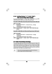
... UTILITY Advanced screen Storage Configuration. B. Using SATA / SATAII HDDs with NCQ and Hot Plug functions (AHCI mode) STEP 1: Set Up BIOS. A. STEP 2: Install Windows® 7 / 7 64-bit / VistaTM / VistaTM 64-bit OS on your system. 2.15 Untied Overclocking Technology... [CPU, PCIE, Async.]. Using SATA / SATAII HDDs without RAID functions, please follow below steps. Please refer to the warning on your system. Enter BIOS SETUP UTILITY Advanced screen Storage Configuration. Set the "SATA Operation Mode" option to [IDE]. STEP 2: Install Windows® 7 / 7 64-bit /...
... UTILITY Advanced screen Storage Configuration. B. Using SATA / SATAII HDDs with NCQ and Hot Plug functions (AHCI mode) STEP 1: Set Up BIOS. A. STEP 2: Install Windows® 7 / 7 64-bit / VistaTM / VistaTM 64-bit OS on your system. 2.15 Untied Overclocking Technology... [CPU, PCIE, Async.]. Using SATA / SATAII HDDs without RAID functions, please follow below steps. Please refer to the warning on your system. Enter BIOS SETUP UTILITY Advanced screen Storage Configuration. Set the "SATA Operation Mode" option to [IDE]. STEP 2: Install Windows® 7 / 7 64-bit /...
User Manual
Page 31
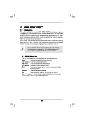
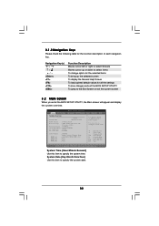
... for reference purpose only, and they may not exactly match what you start up the security features Exit To exit the current screen or the BIOS SETUP UTILITY Use < > key or < > key to choose among the selections on the menu bar, and then press to locate and load the ...set up the default system device to get into the sub screen. 31 3. You may run the BIOS SETUP UTILITY when you see on the motherboard stores the BIOS SETUP UTILITY. Because the BIOS software is constantly being updated, the following selections: Main To set up the system time/date information OC...
... for reference purpose only, and they may not exactly match what you start up the security features Exit To exit the current screen or the BIOS SETUP UTILITY Use < > key or < > key to choose among the selections on the menu bar, and then press to locate and load the ...set up the default system device to get into the sub screen. 31 3. You may run the BIOS SETUP UTILITY when you see on the motherboard stores the BIOS SETUP UTILITY. Because the BIOS software is constantly being updated, the following selections: Main To set up the system time/date information OC...
User Manual
Page 32
... UTILITY Main OC Tweaker Advanced H/W Monitor System Overview System Time System Date [17:00:09] [Mon 06/21/2010] BIOS Version : 770iCafe P1.00 Processor Type : AMD Athlon (tm) II X3 445 Processor (64bit) Processor Speed : 3100MHz Microcode Update : 100F53/10000B6 L1 Cache Size : 384KB L2 Cache ...] Use this item to specify the system time. 3.1.2 Navigation Keys Please check the following table for all the settings To save changes and exit the BIOS SETUP UTILITY To jump to the Exit Screen or exit the current screen 3.2 Main Screen When you enter the...
... UTILITY Main OC Tweaker Advanced H/W Monitor System Overview System Time System Date [17:00:09] [Mon 06/21/2010] BIOS Version : 770iCafe P1.00 Processor Type : AMD Athlon (tm) II X3 445 Processor (64bit) Processor Speed : 3100MHz Microcode Update : 100F53/10000B6 L1 Cache Size : 384KB L2 Cache ...] Use this item to specify the system time. 3.1.2 Navigation Keys Please check the following table for all the settings To save changes and exit the BIOS SETUP UTILITY To jump to the Exit Screen or exit the current screen 3.2 Main Screen When you enter the...

User Manual
Page 33
... Failure Guard Count. Configuration options: [+12%] to [-12%]. 33 Configuration options: [Auto], [CPU, PCIE, Sync.], [CPU, PCIE, Async.] and [Optimized]. Configuration options: [+12%] to [-12%]. BIOS SETUP UTILITY Main OC Tweaker Advanced H/W Monitor Boot Security Exit EZ Overclocking Load CPU EZ OC Setting [Press Enter] CPU Configuration Overclock Mode CPU Frequency...
... Failure Guard Count. Configuration options: [+12%] to [-12%]. 33 Configuration options: [Auto], [CPU, PCIE, Sync.], [CPU, PCIE, Async.] and [Optimized]. Configuration options: [+12%] to [-12%]. BIOS SETUP UTILITY Main OC Tweaker Advanced H/W Monitor Boot Security Exit EZ Overclocking Load CPU EZ OC Setting [Press Enter] CPU Configuration Overclock Mode CPU Frequency...

User Manual
Page 35
... [Auto]. The default value is [Auto]. Power Down Enable Use this to [12CLK]. The default value is [Auto]. TRTP Use this to [30CLK]. Memory Timing BIOS SETUP UTILITY OC Tweaker Memory Timing Memory Controller Mode Power Down Enable Bank Interleaving Channel Interleaving CAS Latency (CL) 9 TRCD 12 TRP 12 TRAS 30...
... [Auto]. The default value is [Auto]. Power Down Enable Use this to [12CLK]. The default value is [Auto]. TRTP Use this to [30CLK]. Memory Timing BIOS SETUP UTILITY OC Tweaker Memory Timing Memory Controller Mode Power Down Enable Bank Interleaving Channel Interleaving CAS Latency (CL) 9 TRCD 12 TRP 12 TRAS 30...

User Manual
Page 39
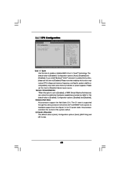
..., Memory Configuration, Chipset Configuration, ACPI Configuration, Storage Configuration, PCIPnP Configuration, SuperIO Configuration, and USB Configuration. ASRock Instant Flash ASRock Instant Flash is a BIOS flash utility embedded in Flash ROM. 3.4 Advanced Screen In this section, you can update your BIOS only in a few clicks without entering operating systems first like MS-DOS or Windows®.
..., Memory Configuration, Chipset Configuration, ACPI Configuration, Storage Configuration, PCIPnP Configuration, SuperIO Configuration, and USB Configuration. ASRock Instant Flash ASRock Instant Flash is a BIOS flash utility embedded in Flash ROM. 3.4 Advanced Screen In this section, you can update your BIOS only in a few clicks without entering operating systems first like MS-DOS or Windows®.
User Manual
Page 40
... MWAIT and requires no hardware support from the chipset. 3.4.1 CPU Configuration Advanced CPU Configuration Cool 'n' Quiet Secure Virtual Machine Enhanced Halt State L3 Cache Allocation BIOS SETUP UTILITY [Auto] [Enabled] [Disabled] [Auto] Enabling this function may reduce CPU voltage and memory frequency, and lead to system stability or compatibility issue with...
... MWAIT and requires no hardware support from the chipset. 3.4.1 CPU Configuration Advanced CPU Configuration Cool 'n' Quiet Secure Virtual Machine Enhanced Halt State L3 Cache Allocation BIOS SETUP UTILITY [Auto] [Enabled] [Disabled] [Auto] Enabling this function may reduce CPU voltage and memory frequency, and lead to system stability or compatibility issue with...
User Manual
Page 41
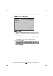
... the onboard HD Audio Front Panel. It allows you to select the type of Primary VGA in case of this feature is plugged. 3.4.2 Chipset Configuration BIOS SETUP UTILITY Advanced Chipset Settings Onboard HD Audio Front Panel OnBoard Lan Primary Graphics Adapter [Auto] [Auto] [Enabled] [PCI] Auto/Enable/Disable Onboard HD Audio...
... the onboard HD Audio Front Panel. It allows you to select the type of Primary VGA in case of this feature is plugged. 3.4.2 Chipset Configuration BIOS SETUP UTILITY Advanced Chipset Settings Onboard HD Audio Front Panel OnBoard Lan Primary Graphics Adapter [Auto] [Auto] [Enabled] [PCI] Auto/Enable/Disable Onboard HD Audio...


