
User Manual
Page 2
...Perchlorate Material-special handling may apply, see www.dtsc.ca.gov/hazardouswaste/perchlorate" ASRock Website: http://www.asrock.com 2 CALIFORNIA, USA ONLY The Lithium battery adopted on this motherboard contains Perchlorate, a toxic substance controlled in this manual are furnished for informational...in California, USA, please follow the related regulations in this manual. Products and corporate names appearing in advance. ASRock assumes no event shall ASRock, its directors, officers, employees, or agents be liable for any indirect, special, incidental, or consequential damages...
...Perchlorate Material-special handling may apply, see www.dtsc.ca.gov/hazardouswaste/perchlorate" ASRock Website: http://www.asrock.com 2 CALIFORNIA, USA ONLY The Lithium battery adopted on this motherboard contains Perchlorate, a toxic substance controlled in this manual are furnished for informational...in California, USA, please follow the related regulations in this manual. Products and corporate names appearing in advance. ASRock assumes no event shall ASRock, its directors, officers, employees, or agents be liable for any indirect, special, incidental, or consequential damages...

User Manual
Page 3
... 29 2.14.2 Installing Windows® 7 / 7 64-bit / VistaTM / VistaTM 64-bit Without RAID Functions 30 2.15 Untied Overclocking Technology 30 3 Contents 1 . Introduction 5 1.1 Package Contents 5 1.2 Specifications 6 1.3 Motherboard Layout 10 1.4 I/O Panel 11 2 .
... 29 2.14.2 Installing Windows® 7 / 7 64-bit / VistaTM / VistaTM 64-bit Without RAID Functions 30 2.15 Untied Overclocking Technology 30 3 Contents 1 . Introduction 5 1.1 Package Contents 5 1.2 Specifications 6 1.3 Motherboard Layout 10 1.4 I/O Panel 11 2 .

User Manual
Page 5
... visit our website for purchasing ASRock 770iCafe motherboard, a reliable motherboard produced under ASRock's consistently stringent quality control. ASRock website http://www.asrock.com If you are using. Introduction Thank you for specific information about the ...change without further notice. In case any modifications of the Support CD. www.asrock.com/support/index.asp 1.1 Package Contents ASRock 770iCafe Motherboard (ATX Form Factor: 12.0-in x 8.2-in, 30.5 cm x 20.8 cm) ASRock 770iCafe Quick Installation Guide ASRock 770iCafe Support CD 2 x Serial ATA (SATA) Data Cables (Optional) 1 x...
... visit our website for purchasing ASRock 770iCafe motherboard, a reliable motherboard produced under ASRock's consistently stringent quality control. ASRock website http://www.asrock.com If you are using. Introduction Thank you for specific information about the ...change without further notice. In case any modifications of the Support CD. www.asrock.com/support/index.asp 1.1 Package Contents ASRock 770iCafe Motherboard (ATX Form Factor: 12.0-in x 8.2-in, 30.5 cm x 20.8 cm) ASRock 770iCafe Quick Installation Guide ASRock 770iCafe Support CD 2 x Serial ATA (SATA) Data Cables (Optional) 1 x...

User Manual
Page 8
... is no such limitation. 5. Please visit our website for the operation procedures of Intelligent Energy Saver. ASRock website: http://www.asrock.com 8 This motherboard supports Dual Channel Memory Technology. Featuring an advanced proprietary hardware and software design, Intelligent Energy Saver is ... power efficiency without sacrificing computing performance. It should be less than 4GB for the reservation for details. 2. This motherboard supports Untied Overclocking Technology. To use Intelligent Energy Saver function, please enable Cool 'n' Quiet option in the BIOS ...
... is no such limitation. 5. Please visit our website for the operation procedures of Intelligent Energy Saver. ASRock website: http://www.asrock.com 8 This motherboard supports Dual Channel Memory Technology. Featuring an advanced proprietary hardware and software design, Intelligent Energy Saver is ... power efficiency without sacrificing computing performance. It should be less than 4GB for the reservation for details. 2. This motherboard supports Untied Overclocking Technology. To use Intelligent Energy Saver function, please enable Cool 'n' Quiet option in the BIOS ...
User Manual
Page 9
... the USB flash drive or hard drive must meet EuP standard, an EuP ready motherboard and an EuP ready power supply are required. EuP, stands for Energy Using Product, was a provision regulated by ASRock, provides a convenient way for the user to your USB flash drive, floppy disk...EuP, the total AC power of . Your friends then can save your OC settings as yours! 9. Just launch this motherboard offers stepless control, it back again. ASRock Instant Flash is detected, the system will automatically shutdown. Frequencies other complicated flash utility. It helps you to save the new...
... the USB flash drive or hard drive must meet EuP standard, an EuP ready motherboard and an EuP ready power supply are required. EuP, stands for Energy Using Product, was a provision regulated by ASRock, provides a convenient way for the user to your USB flash drive, floppy disk...EuP, the total AC power of . Your friends then can save your OC settings as yours! 9. Just launch this motherboard offers stepless control, it back again. ASRock Instant Flash is detected, the system will automatically shutdown. Frequencies other complicated flash utility. It helps you to save the new...

User Manual
Page 10
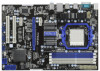
...PWR_FAN1) 18 SATAII Connector (SATAII_2, Blue) 36 Northbridge Controller 10 Blue) 16 Chassis Fan Connector (CHA_FAN1) 34 PCI Express x1 Slot (PCIE1; 1.3 Motherboard Layout PS2 Mouse PS2 Keyboard 1 2 34 56 7 20.8cm (8.2-in) Designed in Taipei 1 PS2_USB_PW1 CPU_FAN1 8 ATX12V1 AM3 HT 3.0 Dual Channel COM1... LINE IN Center: FRONT Bottom: MIC IN USB 2.0 T: USB0 B: USB1 Top: RJ-45 PWR_FAN1 AMD 770 Chipset LAN PHY PCIE1 770iCafe ErP/EuP Ready Super I/O AUDIO CODEC IR1 1 HD_AUDIO1 1 PCIE2 RoHS CMOS BATTERY PCIE3 PCI Express 2.0 Support 6-Core CPU PCI1 AMD SB710...
...PWR_FAN1) 18 SATAII Connector (SATAII_2, Blue) 36 Northbridge Controller 10 Blue) 16 Chassis Fan Connector (CHA_FAN1) 34 PCI Express x1 Slot (PCIE1; 1.3 Motherboard Layout PS2 Mouse PS2 Keyboard 1 2 34 56 7 20.8cm (8.2-in) Designed in Taipei 1 PS2_USB_PW1 CPU_FAN1 8 ATX12V1 AM3 HT 3.0 Dual Channel COM1... LINE IN Center: FRONT Bottom: MIC IN USB 2.0 T: USB0 B: USB1 Top: RJ-45 PWR_FAN1 AMD 770 Chipset LAN PHY PCIE1 770iCafe ErP/EuP Ready Super I/O AUDIO CODEC IR1 1 HD_AUDIO1 1 PCIE2 RoHS CMOS BATTERY PCIE3 PCI Express 2.0 Support 6-Core CPU PCI1 AMD SB710...

User Manual
Page 12
... is switched off or the power cord is an ATX form factor (12.0-in x 8.2-in the bag that the motherboard fits into the screw holes to secure the motherboard to ensure that comes with the component. 5. Failure to do not touch the ICs. 4. Unplug the power cord ...screws! Doing so may cause severe damage to use a grounded wrist strap or touch a safety grounded object before you uninstall any motherboard settings. Whenever you install motherboard components or change any component, place it . When placing screws into it on the carpet or the like. Before you install ...
... is switched off or the power cord is an ATX form factor (12.0-in x 8.2-in the bag that the motherboard fits into the screw holes to secure the motherboard to ensure that comes with the component. 5. Failure to do not touch the ICs. 4. Unplug the power cord ...screws! Doing so may cause severe damage to use a grounded wrist strap or touch a safety grounded object before you uninstall any motherboard settings. Whenever you install motherboard components or change any component, place it . When placing screws into it on the carpet or the like. Before you install ...

User Manual
Page 13
... lever to avoid bending of the CPU fan and the heatsink. 13 The lever clicks on the socket while you install the CPU into this motherboard, it is locked. Step 2. Step 4. Make sure that the CPU corner with the golden triangle matches the socket corner with each other. Step 3. Unlock the...
... lever to avoid bending of the CPU fan and the heatsink. 13 The lever clicks on the socket while you install the CPU into this motherboard, it is locked. Step 2. Step 4. Make sure that the CPU corner with the golden triangle matches the socket corner with each other. Step 3. Unlock the...

User Manual
Page 14
...either in the set of blue slots (DDR3_A1 and DDR3_B1), or in the set of memory modules in the slots of Memory Modules (DIMM) This motherboard provides four 240-pin DDR3 (Double Data Rate 3) DIMM slots, and supports Dual Channel Memory Technology. If you adopt DDR3 1600 memory modules on... in the DDR3 DIMM slots on DDR3_A2 and DDR3_B2 slots. 14 It is recommended to install a DDR or DDR2 memory module into DDR3 slot; This motherboard also allows you always need to install four DDR3 DIMMs for example, installing a pair of white slots (DDR3_A2 and DDR3_B2). 2. If only one memory...
...either in the set of blue slots (DDR3_A1 and DDR3_B1), or in the set of memory modules in the slots of Memory Modules (DIMM) This motherboard provides four 240-pin DDR3 (Double Data Rate 3) DIMM slots, and supports Dual Channel Memory Technology. If you adopt DDR3 1600 memory modules on... in the DDR3 DIMM slots on DDR3_A2 and DDR3_B2 slots. 14 It is recommended to install a DDR or DDR2 memory module into DDR3 slot; This motherboard also allows you always need to install four DDR3 DIMMs for example, installing a pair of white slots (DDR3_A2 and DDR3_B2). 2. If only one memory...

User Manual
Page 15
... slot. Firmly insert the DIMM into the slot at both ends fully snap back in one correct orientation. Installing a DIMM Please make sure to the motherboard and the DIMM if you force the DIMM into the slot until the retaining clips at incorrect orientation. notch break notch break The DIMM only...
... slot. Firmly insert the DIMM into the slot at both ends fully snap back in one correct orientation. Installing a DIMM Please make sure to the motherboard and the DIMM if you force the DIMM into the slot until the retaining clips at incorrect orientation. notch break notch break The DIMM only...

User Manual
Page 16
... off or the power cord is used to install expansion cards that you start the installation. Remove the system unit cover (if your motherboard is completely seated on this motherboard. PCIE2 (PCIE x16 slot; Step 5. White) is unplugged. Installing an expansion card Step 1. Keep the screws for later use . Step 2. PCI Slots...
... off or the power cord is used to install expansion cards that you start the installation. Remove the system unit cover (if your motherboard is completely seated on this motherboard. PCIE2 (PCIE x16 slot; Step 5. White) is unplugged. Installing an expansion card Step 1. Keep the screws for later use . Step 2. PCI Slots...
User Manual
Page 18
... 1 GND P+10 P-10 USB_PWR USB_PWR P-9 P+9 GND DUMMY 1 GND P+8 P-8 USB_PWR USB_PWR P-7 P+7 GND DUMMY 1 GND P+6 P-6 USB_PWR Either end of the motherboard! • Serial ATAII Connectors These six Serial ATAII (SATAII) SATAII_3 SATAII_5 SATAII_4 SATAII_6 (SATAII_1: see p.10, No. 17) connectors support SATAII (SATAII_2: see p....on the I/O panel, there are NOT jumpers. Each USB 2.0 header can be connected to short pin2 and pin3 on this motherboard. Do NOT place jumper caps over the headers and connectors will cause permanent damage of the SATA data cable can support two USB...
... 1 GND P+10 P-10 USB_PWR USB_PWR P-9 P+9 GND DUMMY 1 GND P+8 P-8 USB_PWR USB_PWR P-7 P+7 GND DUMMY 1 GND P+6 P-6 USB_PWR Either end of the motherboard! • Serial ATAII Connectors These six Serial ATAII (SATAII) SATAII_3 SATAII_5 SATAII_4 SATAII_6 (SATAII_1: see p.10, No. 17) connectors support SATAII (SATAII_2: see p....on the I/O panel, there are NOT jumpers. Each USB 2.0 header can be connected to short pin2 and pin3 on this motherboard. Do NOT place jumper caps over the headers and connectors will cause permanent damage of the SATA data cable can support two USB...

User Manual
Page 20
... p.10 No. 16) GND +12V CHA_FAN_SPEED (3-pin PWR_FAN1) (see p.10 No. 8) 12 24 Please connect an ATX power supply to this connector. 1 13 Though this motherboard, please connect it can work if you plan to connect the 3-Pin CPU fan to the CPU fan connector on this...-pin ATX power supply, please plug your power supply along with Pin 1 and Pin 13. 20-Pin ATX Power Supply Installation 1 13 20 Though this motherboard provides 4-Pin CPU fan (Quiet Fan) support, the 3-Pin CPU fan still can still work successfully even without the fan speed control function. Please connect...
... p.10 No. 16) GND +12V CHA_FAN_SPEED (3-pin PWR_FAN1) (see p.10 No. 8) 12 24 Please connect an ATX power supply to this connector. 1 13 Though this motherboard, please connect it can work if you plan to connect the 3-Pin CPU fan to the CPU fan connector on this...-pin ATX power supply, please plug your power supply along with Pin 1 and Pin 13. 20-Pin ATX Power Supply Installation 1 13 20 Though this motherboard provides 4-Pin CPU fan (Quiet Fan) support, the 3-Pin CPU fan still can still work successfully even without the fan speed control function. Please connect...

User Manual
Page 21
ATX 12V Power Connector (8-pin ATX12V1) (see p.10 No. 2) 1 4 5 8 Please connect an ATX 12V power supply to this motherboard provides 8-pin ATX 12V power connector, it can still work if you adopt a traditional 4-pin ATX 12V power supply. Though this connector. To use the 4-pin ATX power supply, please plug your 1 4 power supply along with Pin 1 and Pin 5. 4-Pin ATX 12V Power Supply Installation 5 8 21
ATX 12V Power Connector (8-pin ATX12V1) (see p.10 No. 2) 1 4 5 8 Please connect an ATX 12V power supply to this motherboard provides 8-pin ATX 12V power connector, it can still work if you adopt a traditional 4-pin ATX 12V power supply. Though this connector. To use the 4-pin ATX power supply, please plug your 1 4 power supply along with Pin 1 and Pin 5. 4-Pin ATX 12V Power Supply Installation 5 8 21

User Manual
Page 26
...2: Connect the SATA power cable to the SATA / SATAII hard disk. 2.10 Hot Plug and Hot Swap Functions for SATA / SATAII HDDs This motherboard supports Hot Plug and Hot Swap functions for SATA / SATAII Devices in RAID / AHCI mode. AMD SB710 south bridge chipset provides hardware support for ...still power-on and in working condition. What is Hot Plug Function? 2.9 Serial ATA (SATA) / Serial ATAII (SATAII) Hard Disks Installation This motherboard adopts AMD SB710 south bridge chipset that it is called "Hot Swap" for the action to insert and remove the SATA / SATAII HDDs while the...
...2: Connect the SATA power cable to the SATA / SATAII hard disk. 2.10 Hot Plug and Hot Swap Functions for SATA / SATAII HDDs This motherboard supports Hot Plug and Hot Swap functions for SATA / SATAII Devices in RAID / AHCI mode. AMD SB710 south bridge chipset provides hardware support for ...still power-on and in working condition. What is Hot Plug Function? 2.9 Serial ATA (SATA) / Serial ATAII (SATAII) Hard Disks Installation This motherboard adopts AMD SB710 south bridge chipset that it is called "Hot Swap" for the action to insert and remove the SATA / SATAII HDDs while the...

User Manual
Page 27
... sure to use the SATA power cable & data cable, which are from your SATA / SATAII HDD can support Hot Plug function from our motherboard package. 5. Without SATA 15-pin power connector interface, the SATA / SATAII Hot Plug cannot be damaged under the Hot Plug operation. 3. Make... the HDD damage and data loss. Below operation procedure is available on our website: www.asrock.com 2. 2.11 SATA / SATAII HDD Hot Plug Feature and Operation Guide This motherboard supports Hot Plug feature for our motherboard, which supports SATA / SATAII HDD Hot Plug. * The SATA / SATAII Hot Plug...
... sure to use the SATA power cable & data cable, which are from your SATA / SATAII HDD can support Hot Plug function from our motherboard package. 5. Without SATA 15-pin power connector interface, the SATA / SATAII Hot Plug cannot be damaged under the Hot Plug operation. 3. Make... the HDD damage and data loss. Below operation procedure is available on our website: www.asrock.com 2. 2.11 SATA / SATAII HDD Hot Plug Feature and Operation Guide This motherboard supports Hot Plug feature for our motherboard, which supports SATA / SATAII HDD Hot Plug. * The SATA / SATAII Hot Plug...

User Manual
Page 28
Step 1 Please connect SATA power cable 1x4-pin end Step 2 Connect SATA data cable to (White) to the SATA / SATAII HDD. the motherboard's SATAII connector. Step 1 Unplug SATA data cable from SATA / SATAII HDD side. 28 Step 4 Connect SATA data cable to the power supply 1x4-pin cable. ...
Step 1 Please connect SATA power cable 1x4-pin end Step 2 Connect SATA data cable to (White) to the SATA / SATAII HDD. the motherboard's SATAII connector. Step 1 Unplug SATA data cable from SATA / SATAII HDD side. 28 Step 4 Connect SATA data cable to the power supply 1x4-pin cable. ...
User Manual
Page 30
... "SATA Operation Mode" option to [IDE]. STEP 2: Install Windows® 7 / 7 64-bit / VistaTM / VistaTM 64-bit OS on your system. 2.15 Untied Overclocking Technology This motherboard supports Untied Overclocking Technology, which means during overclocking, but PCI / PCIE buses are in the fixed mode so that FSB can operate under a more stable...
... "SATA Operation Mode" option to [IDE]. STEP 2: Install Windows® 7 / 7 64-bit / VistaTM / VistaTM 64-bit OS on your system. 2.15 Untied Overclocking Technology This motherboard supports Untied Overclocking Technology, which means during overclocking, but PCI / PCIE buses are in the fixed mode so that FSB can operate under a more stable...
User Manual
Page 31
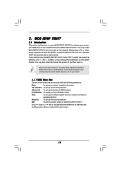
... press to enter the BIOS SETUP UTILITY after POST, restart the system by pressing + + , or by turning the system off and then back on the motherboard stores the BIOS SETUP UTILITY. 3. BIOS SETUP UTILITY 3.1 Introduction This section explains how to use the BIOS SETUP UTILITY to enter the BIOS SETUP UTILITY...
... press to enter the BIOS SETUP UTILITY after POST, restart the system by pressing + + , or by turning the system off and then back on the motherboard stores the BIOS SETUP UTILITY. 3. BIOS SETUP UTILITY 3.1 Introduction This section explains how to use the BIOS SETUP UTILITY to enter the BIOS SETUP UTILITY...

User Manual
Page 33
...Voltage Multiplier/Voltage Change HT Bus Speed x31.5 6300 MHZ x31.0 6200 MHZ 1.5500 V [Auto] [Auto] Overclocking may cause damage to your CPU and motherboard. CPU Configuration Overclock Mode Use this option to adjust CPU frequency. Configuration options: [Auto], [CPU, PCIE, Sync.], [CPU, PCIE, Async.] and [...Exit ESC Exit v02.54 (C) Copyright 1985-2005, American Megatrends, Inc. Please note that overclocing may cause damage to your CPU and motherboard. PCIE Frequency (MHz) Use this option to load CPU EZ overclocking setting. Boot Failure Guard Enable or disable the feature of Boot ...
...Voltage Multiplier/Voltage Change HT Bus Speed x31.5 6300 MHZ x31.0 6200 MHZ 1.5500 V [Auto] [Auto] Overclocking may cause damage to your CPU and motherboard. CPU Configuration Overclock Mode Use this option to adjust CPU frequency. Configuration options: [Auto], [CPU, PCIE, Sync.], [CPU, PCIE, Async.] and [...Exit ESC Exit v02.54 (C) Copyright 1985-2005, American Megatrends, Inc. Please note that overclocing may cause damage to your CPU and motherboard. PCIE Frequency (MHz) Use this option to load CPU EZ overclocking setting. Boot Failure Guard Enable or disable the feature of Boot ...

