User Manual
Page 2
... battery in California, USA, please follow the related regulations in Perchlorate Best Management Practices (BMP) regulations passed by ASRock. "Perchlorate Material-special handling may cause undesired operation. Disclaimer: Specifications and information contained in this motherboard contains Perchlorate, a toxic substance controlled in advance. CALIFORNIA, USA ONLY The Lithium battery adopted on this manual...
... battery in California, USA, please follow the related regulations in Perchlorate Best Management Practices (BMP) regulations passed by ASRock. "Perchlorate Material-special handling may cause undesired operation. Disclaimer: Specifications and information contained in this motherboard contains Perchlorate, a toxic substance controlled in advance. CALIFORNIA, USA ONLY The Lithium battery adopted on this manual...
User Manual
Page 3
Introduction 5 1.1 Package Contents 5 1.2 Specifications 6 1.3 Motherboard Layout 10 1.4 I/O Panel 11 2 . Contents 1 . Installation 12 Pre-installation Precautions 12 2.1 CPU Installation 13 2.2 Installation of CPU Fan and Heatsink 13 2.3 Installation of Memory Modules (...
Introduction 5 1.1 Package Contents 5 1.2 Specifications 6 1.3 Motherboard Layout 10 1.4 I/O Panel 11 2 . Contents 1 . Installation 12 Pre-installation Precautions 12 2.1 CPU Installation 13 2.2 Installation of CPU Fan and Heatsink 13 2.3 Installation of Memory Modules (...
User Manual
Page 5
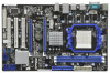
... software might be subject to the hardware installation. www.asrock.com/support/index.asp 1.1 Package Contents ASRock 770DE3L Motherboard (ATX Form Factor: 12.0-in x 7.5-in, 30.5 cm x 19.1 cm) ASRock 770DE3L Quick Installation Guide ASRock 770DE3L Support CD 2 x Serial ATA (SATA) Data Cables (Optional) 1 x I/O Panel Shield 5 ASRock website http://www.asrock.com If you are using. It delivers excellent performance...
... software might be subject to the hardware installation. www.asrock.com/support/index.asp 1.1 Package Contents ASRock 770DE3L Motherboard (ATX Form Factor: 12.0-in x 7.5-in, 30.5 cm x 19.1 cm) ASRock 770DE3L Quick Installation Guide ASRock 770DE3L Support CD 2 x Serial ATA (SATA) Data Cables (Optional) 1 x I/O Panel Shield 5 ASRock website http://www.asrock.com If you are using. It delivers excellent performance...
User Manual
Page 8
... Technology" on our website for the compatible memory modules. ASRock website: http://www.asrock.com 7. It should be less than 4GB for the reservation for the operation procedures of ASRock OC Tuner. This motherboard supports Untied Overclocking Technology. It is able to the memory... proper installation. 3. We are idle. CAUTION! 1. ASRock website http://www.asrock.com 4. If you to surveil your own risk and expense. Due to the components and devices of memory modules on this motherboard, please refer to provide exceptional power saving and improve power...
... Technology" on our website for the compatible memory modules. ASRock website: http://www.asrock.com 7. It should be less than 4GB for the reservation for the operation procedures of ASRock OC Tuner. This motherboard supports Untied Overclocking Technology. It is able to the memory... proper installation. 3. We are idle. CAUTION! 1. ASRock website http://www.asrock.com 4. If you to surveil your own risk and expense. Due to the components and devices of memory modules on this motherboard, please refer to provide exceptional power saving and improve power...
User Manual
Page 9
... supply manufacturer for Energy Using Product, was a provision regulated by ASRock, provides a convenient way for the completed system. 8. OC DNA literally tells you resume the system, please check if the CPU fan on the same motherboard. 10. OC DNA, an exclusive utility developed by European Union ...to perform over-clocking. Before you what it is a BIOS flash utility embedded in Flash ROM. According to access ASRock Instant Flash. With OC DNA, you checking with...
... supply manufacturer for Energy Using Product, was a provision regulated by ASRock, provides a convenient way for the completed system. 8. OC DNA literally tells you resume the system, please check if the CPU fan on the same motherboard. 10. OC DNA, an exclusive utility developed by European Union ...to perform over-clocking. Before you what it is a BIOS flash utility embedded in Flash ROM. According to access ASRock Instant Flash. With OC DNA, you checking with...
User Manual
Page 12
... power is switched off or the power cord is an ATX form factor (12.0-in x 7.5-in, 30.5 cm x 19.1 cm) motherboard. Before you install the motherboard, study the configuration of the following precautions before you handle components. 3. Unplug the power cord from the power supply. Doing so may cause... do not over-tighten the screws! Hold components by the edges and do so may damage the motherboard. 12 When placing screws into the screw holes to secure the motherboard to ensure that the motherboard fits into it on the carpet or the like. Failure to do not touch the ICs. ...
... power is switched off or the power cord is an ATX form factor (12.0-in x 7.5-in, 30.5 cm x 19.1 cm) motherboard. Before you install the motherboard, study the configuration of the following precautions before you handle components. 3. Unplug the power cord from the power supply. Doing so may cause... do not over-tighten the screws! Hold components by the edges and do so may damage the motherboard. 12 When placing screws into the screw holes to secure the motherboard to ensure that the motherboard fits into it on the carpet or the like. Failure to do not touch the ICs. ...

User Manual
Page 13
... avoid bending of the pins. 2.1 CPU Installation Step 1. Unlock the socket by lifting the lever up to dissipate heat. Carefully insert the CPU into this motherboard, it firmly on the side tab to secure the CPU. Lever 90° Up STEP 1: Lift Up The Socket Lever CPU Golden Triangle Socker Corner...
... avoid bending of the pins. 2.1 CPU Installation Step 1. Unlock the socket by lifting the lever up to dissipate heat. Carefully insert the CPU into this motherboard, it firmly on the side tab to secure the CPU. Lever 90° Up STEP 1: Lift Up The Socket Lever CPU Golden Triangle Socker Corner...
User Manual
Page 14
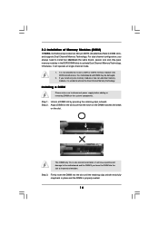
...permanent damage to activate Dual Channel Memory Technology. notch break notch break The DIMM only fits in the DDR3 DIMM slots to the motherboard and the DIMM if you install only one correct orientation. It will operate at single channel mode. 1. It is unable to ...disconnect power supply before adding or removing DIMMs or the system components. Step 2. 2.3 Installation of Memory Modules (DIMM) 770DE3L motherboard provides two 240-pin DDR3 (Double Data Rate 3) DIMM slots, and supports Dual Channel Memory Technology. If you force the DIMM into the slot...
...permanent damage to activate Dual Channel Memory Technology. notch break notch break The DIMM only fits in the DDR3 DIMM slots to the motherboard and the DIMM if you install only one correct orientation. It will operate at single channel mode. 1. It is unable to ...disconnect power supply before adding or removing DIMMs or the system components. Step 2. 2.3 Installation of Memory Modules (DIMM) 770DE3L motherboard provides two 240-pin DDR3 (Double Data Rate 3) DIMM slots, and supports Dual Channel Memory Technology. If you force the DIMM into the slot...
User Manual
Page 15
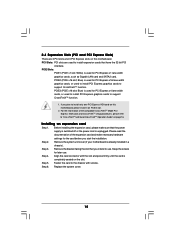
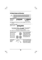
... settings for PCI Express x1 lane width graphics cards, such as Gigabit LAN card and SATA2 card. Remove the system unit cover (if your motherboard is completely seated on PCIE2 slot. 2. Step 3. Step 4. Step 6. Replace the system cover. 15 2.4 Expansion Slots (PCI and PCI ... unplugged. For the information of the expansion card and make sure that you plan to "CrossFireXTM and Quad CrossFireXTM Operation Guide" on this motherboard. Installing an expansion card Step 1. Align the card connector with screws. PCIE Slots: PCIE1 (PCIE x1 slot; Remove the bracket facing ...
... settings for PCI Express x1 lane width graphics cards, such as Gigabit LAN card and SATA2 card. Remove the system unit cover (if your motherboard is completely seated on PCIE2 slot. 2. Step 3. Step 4. Step 6. Replace the system cover. 15 2.4 Expansion Slots (PCI and PCI ... unplugged. For the information of the expansion card and make sure that you plan to "CrossFireXTM and Quad CrossFireXTM Operation Guide" on this motherboard. Installing an expansion card Step 1. Align the card connector with screws. PCIE Slots: PCIE1 (PCIE x1 slot; Remove the bracket facing ...
User Manual
Page 16
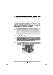
...with Service Pack 2 / VistaTM / 7 OS. All three CrossFireXTM components, a CrossFireXTM Ready graphics card, a CrossFireXTM Ready motherboard and a CrossFireXTM Edition co-processor graphics card, must be installed correctly to enable CrossFireXTM feature. CrossFireXTM technology offers the most advantageous... feature are properly seated on the slots. 16 Step 1. 2.5 CrossFireXTM and Quad CrossFireXTM Operation Guide This motherboard supports CrossFireXTM and Quad CrossFireXTM feature. Insert one Radeon graphics card into PCIE2 slot and the other CrossFireXTM cards...
...with Service Pack 2 / VistaTM / 7 OS. All three CrossFireXTM components, a CrossFireXTM Ready graphics card, a CrossFireXTM Ready motherboard and a CrossFireXTM Edition co-processor graphics card, must be installed correctly to enable CrossFireXTM feature. CrossFireXTM technology offers the most advantageous... feature are properly seated on the slots. 16 Step 1. 2.5 CrossFireXTM and Quad CrossFireXTM Operation Guide This motherboard supports CrossFireXTM and Quad CrossFireXTM feature. Insert one Radeon graphics card into PCIE2 slot and the other CrossFireXTM cards...
User Manual
Page 17
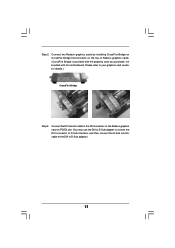
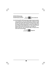
Connect two Radeon graphics cards by installing CrossFire Bridge on CrossFire Bridge Interconnects on PCIE2 slot. (You may use the DVI to D-Sub adapter to convert the DVI connector to D-Sub interface, and then connect the D-Sub monitor cable to the DVI to D-Sub adapter.) 17 Please refer to the DVI connector on the Radeon graphics card on the top of Radeon graphics cards. (CrossFire Bridge is provided with the graphics card you purchase, not bundled with this motherboard. Connect the DVI monitor cable to your graphics card vendor for details.) CrossFire Bridge Step 3. Step 2.
Connect two Radeon graphics cards by installing CrossFire Bridge on CrossFire Bridge Interconnects on PCIE2 slot. (You may use the DVI to D-Sub adapter to convert the DVI connector to D-Sub interface, and then connect the D-Sub monitor cable to the DVI to D-Sub adapter.) 17 Please refer to the DVI connector on the Radeon graphics card on the top of Radeon graphics cards. (CrossFire Bridge is provided with the graphics card you purchase, not bundled with this motherboard. Connect the DVI monitor cable to your graphics card vendor for details.) CrossFire Bridge Step 3. Step 2.
User Manual
Page 20
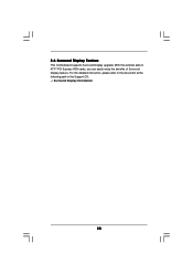
2.6 Surround Display Feature This motherboard supports Surround Display upgrade. For the detailed instruction, please refer to the document at the following path in the Support CD: ..\ Surround Display Information 20 With the external add-on ATITM PCI Express VGA cards, you can easily enjoy the benefits of Surround Display feature.
2.6 Surround Display Feature This motherboard supports Surround Display upgrade. For the detailed instruction, please refer to the document at the following path in the Support CD: ..\ Surround Display Information 20 With the external add-on ATITM PCI Express VGA cards, you can easily enjoy the benefits of Surround Display feature.
User Manual
Page 22
...) is higher than 50% under S3 (Suspend to RAM), S4 (Suspend to submit EuP standard. If you may short pin2 and pin3. With an ASRock EuP ready motherboard and a power supply that when EUP_LAN jumper is set to enabled, the Wake-On-LAN function under 100mA current consumption, your system is able.... 35) (EUP_AUDIO1, 3-pin jumper, see p.10 No. 31) EUP_LAN1 EUP_AUDIO1 Default (Enable EuP) Note: EUP_LAN and EUP_AUDIO jumper design decreases the power consumption of this motherboard to disable this power saving function, you want to meet EuP standard.
...) is higher than 50% under S3 (Suspend to RAM), S4 (Suspend to submit EuP standard. If you may short pin2 and pin3. With an ASRock EuP ready motherboard and a power supply that when EUP_LAN jumper is set to enabled, the Wake-On-LAN function under 100mA current consumption, your system is able.... 35) (EUP_AUDIO1, 3-pin jumper, see p.10 No. 31) EUP_LAN1 EUP_AUDIO1 Default (Enable EuP) Note: EUP_LAN and EUP_AUDIO jumper design decreases the power consumption of this motherboard to disable this power saving function, you want to meet EuP standard.
User Manual
Page 23
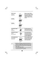
... Gb/s data transfer rate. Primary IDE connector (Blue) (39-pin IDE1, see p.10 No. 8) PIN1 IDE1 connect the blue end to the motherboard connect the black end to the IDE devices 80-conductor ATA 66/100/133 cable Note: Please refer to Pin1 Note: Make sure the red...cable is plugged into Pin1 side of your IDE device vendor for internal storage devices. Serial ATA (SATA) Data Cable (Optional) Either end of the motherboard! • Floppy Connector (33-pin FLOPPY1) (see p.10, No. 15) SATAII_1 SATAII_6 SATAII_5 SATAII_4 SATAII_3 These six Serial ATAII (SATAII) connectors ...
... Gb/s data transfer rate. Primary IDE connector (Blue) (39-pin IDE1, see p.10 No. 8) PIN1 IDE1 connect the blue end to the motherboard connect the black end to the IDE devices 80-conductor ATA 66/100/133 cable Note: Please refer to Pin1 Note: Make sure the red...cable is plugged into Pin1 side of your IDE device vendor for internal storage devices. Serial ATA (SATA) Data Cable (Optional) Either end of the motherboard! • Floppy Connector (33-pin FLOPPY1) (see p.10, No. 15) SATAII_1 SATAII_6 SATAII_5 SATAII_4 SATAII_3 These six Serial ATAII (SATAII) connectors ...
User Manual
Page 24
... to function correctly. C. B. Connect Audio_R (RIN) to OUT2_R and Audio_L (LIN) to MIC2_L. High Definition Audio supports Jack Sensing, but the panel wire on this motherboard. If you to the front panel audio header as a CD-ROM, DVD-ROM, TV tuner card, or MPEG card. Connect Ground (GND) to install your...
... to function correctly. C. B. Connect Audio_R (RIN) to OUT2_R and Audio_L (LIN) to MIC2_L. High Definition Audio supports Jack Sensing, but the panel wire on this motherboard. If you to the front panel audio header as a CD-ROM, DVD-ROM, TV tuner card, or MPEG card. Connect Ground (GND) to install your...
User Manual
Page 25
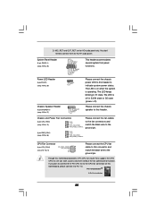
... CPU Fan Connector (4-pin CPU_FAN1) (see p.10 No. 29) 1 PLEDPLED+ PLED+ Please connect the chassis power LED to this header to this motherboard, please connect it to the ground pin. Power LED Header (3-pin PLED1) (see p.10 No. 5) FAN_SPEED_CONTROL 4 CPU_FAN_SPEED 3 +12V 2 GND ...1 Please connect the CPU fan cable to this motherboard provides 4-Pin CPU fan (Quiet Fan) support, the 3-Pin CPU fan still can work successfully even without the fan speed control function. D. ...
... CPU Fan Connector (4-pin CPU_FAN1) (see p.10 No. 29) 1 PLEDPLED+ PLED+ Please connect the chassis power LED to this header to this motherboard, please connect it to the ground pin. Power LED Header (3-pin PLED1) (see p.10 No. 5) FAN_SPEED_CONTROL 4 CPU_FAN_SPEED 3 +12V 2 GND ...1 Please connect the CPU fan cable to this motherboard provides 4-Pin CPU fan (Quiet Fan) support, the 3-Pin CPU fan still can work successfully even without the fan speed control function. D. ...
User Manual
Page 26
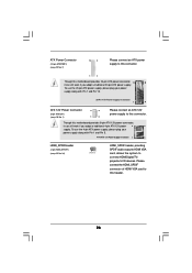
...VGA card, allows the system to connect HDMI Digital TV/ projector/LCD devices. Please connect the HDMI_SPDIF connector of HDMI VGA card to this motherboard provides 24-pin ATX power connector, 12 24 it can still work if you adopt a traditional 20-pin ATX power supply. To use... Power Supply Installation 1 13 ATX 12V Power Connector (8-pin ATX12V1) (see p.10 No. 1) 4 8 1 6 Please connect an ATX 12V power supply to this motherboard provides 8-pin ATX 12V power connector, it can still work if you adopt a traditional 4-pin ATX 12V power 4 8 supply. Though this header. 26
...VGA card, allows the system to connect HDMI Digital TV/ projector/LCD devices. Please connect the HDMI_SPDIF connector of HDMI VGA card to this motherboard provides 24-pin ATX power connector, 12 24 it can still work if you adopt a traditional 20-pin ATX power supply. To use... Power Supply Installation 1 13 ATX 12V Power Connector (8-pin ATX12V1) (see p.10 No. 1) 4 8 1 6 Please connect an ATX 12V power supply to this motherboard provides 8-pin ATX 12V power connector, it can still work if you adopt a traditional 4-pin ATX 12V power 4 8 supply. Though this header. 26
User Manual
Page 28
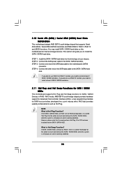
...is called "Hot Plug" for SATA / SATAII Devices in RAID / AHCI mode. 2.10 Serial ATA (SATA) / Serial ATAII (SATAII) Hard Disks Installation This motherboard adopts AMD SB710 south bridge chipset that it cannot perform Hot Plug if the OS has been installed into the drive bays of your chassis...4: Connect the other end of the SATA data cable to the SATA / SATAII hard disk. You may install SATA / SATAII hard disks on this motherboard for SATA host controllers developed thru a joint industry effort. What is Hot Plug Function? STEP 3: Connect one end of the SATA data cable to...
...is called "Hot Plug" for SATA / SATAII Devices in RAID / AHCI mode. 2.10 Serial ATA (SATA) / Serial ATAII (SATAII) Hard Disks Installation This motherboard adopts AMD SB710 south bridge chipset that it cannot perform Hot Plug if the OS has been installed into the drive bays of your chassis...4: Connect the other end of the SATA data cable to the SATA / SATAII hard disk. You may install SATA / SATAII hard disks on this motherboard for SATA host controllers developed thru a joint industry effort. What is Hot Plug Function? STEP 3: Connect one end of the SATA data cable to...
User Manual
Page 29
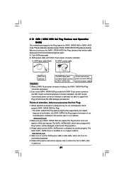
...HDD damage and data loss. Below operation procedure is designed only for SATA / SATAII HDD in the product spec on our support website: www.asrock.com 4. Please follow below instructions step by the chipset because of its limitation, the SATA / SATAII Hot Plug support information of SATA / ...SATAII HDD Hot Plug feature carefully. Please read below cable accessories from your SATA / SATAII HDD can support Hot Plug function from the motherboard gift box pack. SATA data cable (Red) B. Points of attention, before you process the SATA / SATAII HDD Hot Plug, please check below ...
...HDD damage and data loss. Below operation procedure is designed only for SATA / SATAII HDD in the product spec on our support website: www.asrock.com 4. Please follow below instructions step by the chipset because of its limitation, the SATA / SATAII Hot Plug support information of SATA / ...SATAII HDD Hot Plug feature carefully. Please read below cable accessories from your SATA / SATAII HDD can support Hot Plug function from the motherboard gift box pack. SATA data cable (Red) B. Points of attention, before you process the SATA / SATAII HDD Hot Plug, please check below ...
User Manual
Page 30
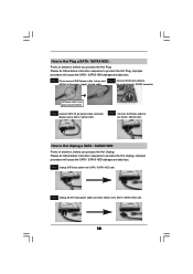
... power cable connector (Black) end to the SATA / SATAII HDD. Step 2 Unplug SATA 15-pin power cable connector (Black) from SATA / SATAII HDD side. the motherboard's SATAII connector. Step 4 Connect SATA data cable to SATA / SATAII HDD. Step 1 Unplug SATA data cable from SATA / SATAII HDD side. 30 Step 1 Please connect...
... power cable connector (Black) end to the SATA / SATAII HDD. Step 2 Unplug SATA 15-pin power cable connector (Black) from SATA / SATAII HDD side. the motherboard's SATAII connector. Step 4 Connect SATA data cable to SATA / SATAII HDD. Step 1 Unplug SATA data cable from SATA / SATAII HDD side. 30 Step 1 Please connect...

