
User Manual
Page 11
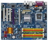
... PCIE1 RAID FSB2 1 1 FSB3 FSB1 1 AGI_EXPRESS1 PCI1 PCI EXPRESS 4Mb BIOS PCI2 1 WIFI PCI3 CD1 HD_AUDIO1 HDMI_SPDIF1 1 1 FLOPPY1 IR1 1 4Core1600Twins-P35D FSB1600 Dual Channel Quad Core CPU IDE1 1 CLRCMOS1 CMOS Battery Intel ICH9 SATAII CHA_FAN1 SATAII_5 (Port4) SATAII_6 (Port5) SATAII_1 (Port0) USB8_9 1 ... 15 27 26 25 24 23 22 2120 191817 16 1 PS2_USB_PWR1 Jumper 2 ATX 12V Connector (ATX12V1) 3 CPU Fan Connector (CPU_FAN1) 4 775-Pin CPU Socket 5 North Bridge Controller 6 2 x 240-pin DDR2 DIMM Slots (Dual Channel A: DDRII_1, DDRII_3; Yellow) 7 2 x 240-pin DDR2 DIMM ...
... PCIE1 RAID FSB2 1 1 FSB3 FSB1 1 AGI_EXPRESS1 PCI1 PCI EXPRESS 4Mb BIOS PCI2 1 WIFI PCI3 CD1 HD_AUDIO1 HDMI_SPDIF1 1 1 FLOPPY1 IR1 1 4Core1600Twins-P35D FSB1600 Dual Channel Quad Core CPU IDE1 1 CLRCMOS1 CMOS Battery Intel ICH9 SATAII CHA_FAN1 SATAII_5 (Port4) SATAII_6 (Port5) SATAII_1 (Port0) USB8_9 1 ... 15 27 26 25 24 23 22 2120 191817 16 1 PS2_USB_PWR1 Jumper 2 ATX 12V Connector (ATX12V1) 3 CPU Fan Connector (CPU_FAN1) 4 775-Pin CPU Socket 5 North Bridge Controller 6 2 x 240-pin DDR2 DIMM Slots (Dual Channel A: DDRII_1, DDRII_3; Yellow) 7 2 x 240-pin DDR2 DIMM ...
User Manual
Page 14
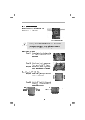
...open position at approximately 100 degrees. 2.3 CPU Installation For the installation of Intel 775-LAND CPU, please follow the steps below. 775-Pin Socket Overview Before you insert the 775-LAND CPU into the socket if above situation is any bent pin on the hook to clear retention tab... Pin1 and the two orientation key notches. Step 1. Pin1 orientation key notch orientation key notch Pin1 alignment key alignment key 775-LAND CPU 775-Pin Socket 14 black line black line Do not force to fully open position at approximately 135 degrees. Step 1-3. Rotate the load lever...
...open position at approximately 100 degrees. 2.3 CPU Installation For the installation of Intel 775-LAND CPU, please follow the steps below. 775-Pin Socket Overview Before you insert the 775-LAND CPU into the socket if above situation is any bent pin on the hook to clear retention tab... Pin1 and the two orientation key notches. Step 1. Pin1 orientation key notch orientation key notch Pin1 alignment key alignment key 775-LAND CPU 775-Pin Socket 14 black line black line Do not force to fully open position at approximately 135 degrees. Step 1-3. Rotate the load lever...
User Manual
Page 16
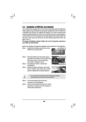
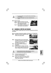
...connector (CPU_FAN1, see page 11, No. 3). Step 4. Step 5. Place the heatsink onto the socket. Secure excess cable with fan operation or contact other . Ensure that supports Intel 775-LAND CPU. Step 2. If you need to spray thermal interface material between the CPU and the ... motherboard. Step 1. Apply thermal interface material onto center of the heatsink for 775-LAND CPU. Before you installed the heatsink, you press down on the socket surface. Below is equipped with 775-Pin socket that the CPU and the heatsink are oriented on the motherboard (CPU_FAN1, see...
...connector (CPU_FAN1, see page 11, No. 3). Step 4. Step 5. Place the heatsink onto the socket. Secure excess cable with fan operation or contact other . Ensure that supports Intel 775-LAND CPU. Step 2. If you need to spray thermal interface material between the CPU and the ... motherboard. Step 1. Apply thermal interface material onto center of the heatsink for 775-LAND CPU. Before you installed the heatsink, you press down on the socket surface. Below is equipped with 775-Pin socket that the CPU and the heatsink are oriented on the motherboard (CPU_FAN1, see...
Quick Installation Guide
Page 2
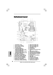
... Power Connector (ATXPWR1) 36 eSATAII Connector (eSATAII) 2 ASRock 4Core1600Twins-P35D Motherboard Orange) 8 2 x 240-pin DDR3 DIMM Slots (Dual Channel C: DDR3_A1, DDR3_B1; Yellow) 7 2 x 240-pin DDR2 DIMM Slots (Dual Channel B: DDRII_2, DDRII_4; Motherboard Layout English 1 PS2_USB_PWR1 Jumper 2 ATX 12V Connector (ATX12V1) 3 CPU Fan Connector (CPU_FAN1) 4 775-Pin CPU Socket 5 North Bridge Controller 6 2 x 240-pin DDR2 DIMM...
... Power Connector (ATXPWR1) 36 eSATAII Connector (eSATAII) 2 ASRock 4Core1600Twins-P35D Motherboard Orange) 8 2 x 240-pin DDR3 DIMM Slots (Dual Channel C: DDR3_A1, DDR3_B1; Yellow) 7 2 x 240-pin DDR2 DIMM Slots (Dual Channel B: DDRII_2, DDRII_4; Motherboard Layout English 1 PS2_USB_PWR1 Jumper 2 ATX 12V Connector (ATX12V1) 3 CPU Fan Connector (CPU_FAN1) 4 775-Pin CPU Socket 5 North Bridge Controller 6 2 x 240-pin DDR2 DIMM...

Quick Installation Guide
Page 9
...component, place it on the carpet or the like. English 775-Pin Socket Overview Before you handle components. 3. Unplug the power cord from the wall socket before you insert the 775-LAND CPU into the socket if above minimum hardware requirements in the bag that comes with... Hold components by the edges and do not touch the ICs. 4. Otherwise, the CPU will be seriously damaged. 9 ASRock 4Core1600Twins-P35D Motherboard To avoid damaging the motherboard components due to the motherboard, peripherals, and/or components. 2. Installation Pre-installation Precautions Take note ...
...component, place it on the carpet or the like. English 775-Pin Socket Overview Before you handle components. 3. Unplug the power cord from the wall socket before you insert the 775-LAND CPU into the socket if above minimum hardware requirements in the bag that comes with... Hold components by the edges and do not touch the ICs. 4. Otherwise, the CPU will be seriously damaged. 9 ASRock 4Core1600Twins-P35D Motherboard To avoid damaging the motherboard components due to the motherboard, peripherals, and/or components. 2. Installation Pre-installation Precautions Take note ...
Quick Installation Guide
Page 10
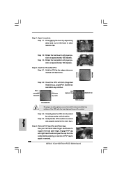
...): Use your left hand index finger and thumb to fully open position at approximately 100 degrees. Step 1-3. Open the socket: Step 1-1. Rotate the load lever to assist in removal. 10 ASRock 4Core1600Twins-P35D Motherboard Insert the 775-LAND CPU: Step 2-1. black line black line English Step 2-2. Disengaging the lever by using a purely vertical motion. Step...
...): Use your left hand index finger and thumb to fully open position at approximately 100 degrees. Step 1-3. Open the socket: Step 1-1. Rotate the load lever to assist in removal. 10 ASRock 4Core1600Twins-P35D Motherboard Insert the 775-LAND CPU: Step 2-1. black line black line English Step 2-2. Disengaging the lever by using a purely vertical motion. Step...
Quick Installation Guide
Page 11
...of IHS on load plate, engage the load lever. Step 5. Secure excess cable with fan operation or contact other components. 11 ASRock 4Core1600Twins-P35D Motherboard English Step 4. Below is recommended to use the cap tab to the instruction manuals of CPU Fan and Heatsink For proper... be secured on fastener caps with the motherboard throughholes. Close the socket: Step 4-1. Step 4-2. While pressing down the fasteners without rotating them clockwise, the heatsink cannot be placed if returning the motherboard for 775-LAND CPU. Step 2. If you press down lightly on the...
...of IHS on load plate, engage the load lever. Step 5. Secure excess cable with fan operation or contact other components. 11 ASRock 4Core1600Twins-P35D Motherboard English Step 4. Below is recommended to use the cap tab to the instruction manuals of CPU Fan and Heatsink For proper... be secured on fastener caps with the motherboard throughholes. Close the socket: Step 4-1. Step 4-2. While pressing down the fasteners without rotating them clockwise, the heatsink cannot be placed if returning the motherboard for 775-LAND CPU. Step 2. If you press down lightly on the...