
User Manual
Page 4
... 44 3.1 Introduction 44 3.1.1 BIOS Menu Bar 44 3.1.2 Navigation Keys 44 3.2 Main Screen 44 3.3 Advanced Screen 45 3.3.1 CPU Configuration 46 3.3.2 Chipset Configuration 48 3.3.3 ACPI Configuration 50 3.3.4 IDE Configuration 51 3.3.5 PCIPnP ...
... 44 3.1 Introduction 44 3.1.1 BIOS Menu Bar 44 3.1.2 Navigation Keys 44 3.2 Main Screen 44 3.3 Advanced Screen 45 3.3.1 CPU Configuration 46 3.3.2 Chipset Configuration 48 3.3.3 ACPI Configuration 50 3.3.4 IDE Configuration 51 3.3.5 PCIPnP ...

User Manual
Page 5
... Contents ASRock 4Core1600Twins-P35D Motherboard (ATX Form Factor: 12.0-in x 9.6-in, 30.5 cm x 24.4 cm) ASRock 4Core1600Twins-P35D Quick Installation Guide ASRock 4Core1600Twins-P35D Support CD One 80-conductor Ultra ATA 66/100/133 IDE Ribbon Cable One Ribbon Cable for purchasing ASRock 4Core1600Twins-P35D motherboard, a reliable motherboard produced under ASRock's consistently stringent quality control. Because the motherboard specifications and the BIOS software might...
... Contents ASRock 4Core1600Twins-P35D Motherboard (ATX Form Factor: 12.0-in x 9.6-in, 30.5 cm x 24.4 cm) ASRock 4Core1600Twins-P35D Quick Installation Guide ASRock 4Core1600Twins-P35D Support CD One 80-conductor Ultra ATA 66/100/133 IDE Ribbon Cable One Ribbon Cable for purchasing ASRock 4Core1600Twins-P35D motherboard, a reliable motherboard produced under ASRock's consistently stringent quality control. Because the motherboard specifications and the BIOS software might...

User Manual
Page 7
... audio connector - 3 x USB 2.0 headers (support 6 USB 2.0 ports) (see CAUTION 10) - 1 x WiFi header (see CAUTION 14) - ASRock U-COP (see CAUTION 11) BIOS Feature - 4Mb AMI BIOS - FCC, CE, WHQL * For detailed product information, please visit our website: http://www.asrock.com 7 SLI/XFIRE power connector - Supports "Plug and Play" - Supports jumperfree - T. (Intelligent Overclocking Technology) Support...
... audio connector - 3 x USB 2.0 headers (support 6 USB 2.0 ports) (see CAUTION 10) - 1 x WiFi header (see CAUTION 14) - ASRock U-COP (see CAUTION 11) BIOS Feature - 4Mb AMI BIOS - FCC, CE, WHQL * For detailed product information, please visit our website: http://www.asrock.com 7 SLI/XFIRE power connector - Supports "Plug and Play" - Supports jumperfree - T. (Intelligent Overclocking Technology) Support...

User Manual
Page 8
... by overclocking. FSB1600-CPU will run at your own risk and expense. When you use a FSB1600-CPU on this motherboard, it will operate in the BIOS, applying Untied Overclocking Technology, or using the thirdparty overclocking tools. It should be done at DDR2 960 if you use a FSB1600-CPU on page 17...
... by overclocking. FSB1600-CPU will run at your own risk and expense. When you use a FSB1600-CPU on this motherboard, it will operate in the BIOS, applying Untied Overclocking Technology, or using the thirdparty overclocking tools. It should be done at DDR2 960 if you use a FSB1600-CPU on page 17...

User Manual
Page 11
... Header (USB6_7, Blue) 19 USB 2.0 Header (USB4_5, Blue) 20 USB 2.0 Header (USB8_9, Blue) 21 South Bridge Controller 22 SPI BIOS Chip 23 WiFi Header (WiFi) 24 DeskExpress Hot Plug Detection Header (IR1) 25 Floppy Connector (FLOPPY1) 26 HDMI_SPDIF Header (HDMI_SPDIF1) 27 Front ...IN LAN PHY Super I/O AUDIO CODEC PCIE1 RAID FSB2 1 1 FSB3 FSB1 1 AGI_EXPRESS1 PCI1 PCI EXPRESS 4Mb BIOS PCI2 1 WIFI PCI3 CD1 HD_AUDIO1 HDMI_SPDIF1 1 1 FLOPPY1 IR1 1 4Core1600Twins-P35D FSB1600 Dual Channel Quad Core CPU IDE1 1 CLRCMOS1 CMOS Battery Intel ICH9 SATAII CHA_FAN1 SATAII_5 (Port4) SATAII_6 (...
... Header (USB6_7, Blue) 19 USB 2.0 Header (USB4_5, Blue) 20 USB 2.0 Header (USB8_9, Blue) 21 South Bridge Controller 22 SPI BIOS Chip 23 WiFi Header (WiFi) 24 DeskExpress Hot Plug Detection Header (IR1) 25 Floppy Connector (FLOPPY1) 26 HDMI_SPDIF Header (HDMI_SPDIF1) 27 Front ...IN LAN PHY Super I/O AUDIO CODEC PCIE1 RAID FSB2 1 1 FSB3 FSB1 1 AGI_EXPRESS1 PCI1 PCI EXPRESS 4Mb BIOS PCI2 1 WIFI PCI3 CD1 HD_AUDIO1 HDMI_SPDIF1 1 1 FLOPPY1 IR1 1 4Core1600Twins-P35D FSB1600 Dual Channel Quad Core CPU IDE1 1 CLRCMOS1 CMOS Battery Intel ICH9 SATAII CHA_FAN1 SATAII_5 (Port4) SATAII_6 (...

User Manual
Page 25
... the jumper cap is placed on these 2 pins. The data in CMOS. If you need to clear the CMOS when you just finish updating the BIOS, you to short pin2 and pin3 on pins, the jumper is "Open". lustration shows a 3-pin jumper whose pin1 and pin2 are setup. After waiting for... setup, please turn off the computer and unplug the power cord from the power supply. Note: To select +5VSB, it down before you update the BIOS. If no jumper cap is placed on CLRCMOS1 for PS/2 or USB wake up the system first, and then shut it requires 2 Amp and higher...
... the jumper cap is placed on these 2 pins. The data in CMOS. If you need to clear the CMOS when you just finish updating the BIOS, you to short pin2 and pin3 on pins, the jumper is "Open". lustration shows a 3-pin jumper whose pin1 and pin2 are setup. After waiting for... setup, please turn off the computer and unplug the power cord from the power supply. Note: To select +5VSB, it down before you update the BIOS. If no jumper cap is placed on CLRCMOS1 for PS/2 or USB wake up the system first, and then shut it requires 2 Amp and higher...

User Manual
Page 29
... Please follow the instruction in our manual and chassis manual to MIC2_L. Connect Mic_IN (MIC) to install your system. 2. Enter BIOS Setup Utility. C. This header supports the Hot Plug detection function for front panel audio cable that allows convenient connection and control of...Panel Audio Header (9-pin HD_AUDIO1) (see p.11 No. 27) GND PRESENCE# MIC_RET OUT_RET 1 OUT2_L J_SENSE OUT2_R MIC2_R MIC2_L This is an interface for ASRock DeskExpress. Set the Front Panel Control option from sound sources such as below: A. D. WiFi Header (11-pin WIFI) (see p.11 No. ...
... Please follow the instruction in our manual and chassis manual to MIC2_L. Connect Mic_IN (MIC) to install your system. 2. Enter BIOS Setup Utility. C. This header supports the Hot Plug detection function for front panel audio cable that allows convenient connection and control of...Panel Audio Header (9-pin HD_AUDIO1) (see p.11 No. 27) GND PRESENCE# MIC_RET OUT_RET 1 OUT2_L J_SENSE OUT2_R MIC2_R MIC2_L This is an interface for ASRock DeskExpress. Set the Front Panel Control option from sound sources such as below: A. D. WiFi Header (11-pin WIFI) (see p.11 No. ...

User Manual
Page 33
...Hot Plug capability that enables you may simply plug your eSATAII hard disk to the eSATAII ports while the system is power-on and in BIOS setup to IDE mode, Hot Plug function is not supported with eSATAII interface, you to 42 for external interface. If you to enjoy...replace USB 2.0 and IEEE 1394 to be a trend for detailed information of opening your chassis to exchange your eSATAII devices to use eSATAII function in BIOS setup to AHCI mode, Hot Plug function is up to 3000Mb/s, which is eSATAII? NOTE: 1. This motherboard supports eSATAII interface, the external SATAII ...
...Hot Plug capability that enables you may simply plug your eSATAII hard disk to the eSATAII ports while the system is power-on and in BIOS setup to IDE mode, Hot Plug function is not supported with eSATAII interface, you to 42 for external interface. If you to enjoy...replace USB 2.0 and IEEE 1394 to be a trend for detailed information of opening your chassis to exchange your eSATAII devices to use eSATAII function in BIOS setup to AHCI mode, Hot Plug function is up to 3000Mb/s, which is eSATAII? NOTE: 1. This motherboard supports eSATAII interface, the external SATAII ...

User Manual
Page 40
... to your system. A. Set "SATAII Configuration" to format and copy files [YN]? Using SATA / SATAII HDDs and eSATAII devices with NCQ function STEP 1: Set Up BIOS. When you see these messages, Please insert a diskette into the floppy diskette. 40 D. Start to [Enhanced], and then in the option "Configure SATAII as the...
... to your system. A. Set "SATAII Configuration" to format and copy files [YN]? Using SATA / SATAII HDDs and eSATAII devices with NCQ function STEP 1: Set Up BIOS. When you see these messages, Please insert a diskette into the floppy diskette. 40 D. Start to [Enhanced], and then in the option "Configure SATAII as the...

User Manual
Page 41
...After reading the floppy disk, the driver will be presented. Using SATA / SATAII HDDs and eSATAII devices with NCQ function STEP 1: Set Up BIOS. At the beginning of Windows® setup, press F6 to continue the installation. 41 You may select: "Intel(R) ICH9 SATA AHCI Controller ... RAID functions, please follow the instruction to install Windows® VistaTM / VistaTM 64-bit OS on your system. A. A. Enter BIOS SETUP UTILITY Advanced screen IDE Configuration. page, please insert the ASRock Support CD into the optical drive again to install a thirdparty AHCI driver.
...After reading the floppy disk, the driver will be presented. Using SATA / SATAII HDDs and eSATAII devices with NCQ function STEP 1: Set Up BIOS. At the beginning of Windows® setup, press F6 to continue the installation. 41 You may select: "Intel(R) ICH9 SATA AHCI Controller ... RAID functions, please follow the instruction to install Windows® VistaTM / VistaTM 64-bit OS on your system. A. A. Enter BIOS SETUP UTILITY Advanced screen IDE Configuration. page, please insert the ASRock Support CD into the optical drive again to install a thirdparty AHCI driver.

User Manual
Page 42
..., but PCI / PCIE buses are in the option "Configure SATAII as", please set the selection from [Auto] to [IDE]. After setting up BIOS. STEP 2: Install Windows® VistaTM / VistaTM 64-bit OS on your system. Therefore, CPU FSB is untied during overclocking, FSB enjoys better ...margin due to fixed PCI / PCIE buses. A. B. Before you enable Untied Overclocking function, please enter "Overclock Mode" option of BIOS setup to set the option to [Manual]. Please refer to the warning on page 8 for the possible overclocking risk before you apply Untied Overclocking ...
..., but PCI / PCIE buses are in the option "Configure SATAII as", please set the selection from [Auto] to [IDE]. After setting up BIOS. STEP 2: Install Windows® VistaTM / VistaTM 64-bit OS on your system. Therefore, CPU FSB is untied during overclocking, FSB enjoys better ...margin due to fixed PCI / PCIE buses. A. B. Before you enable Untied Overclocking function, please enter "Overclock Mode" option of BIOS setup to set the option to [Manual]. Please refer to the warning on page 8 for the possible overclocking risk before you apply Untied Overclocking ...

User Manual
Page 43
...then press to get into the sub screen. 43 You may also restart by pressing the reset button on the motherboard stores the BIOS SETUP UTILITY. Because the BIOS software is constantly being updated, the following selections: Main To set up the system time/date information Advanced To set up the... advanced BIOS features H/W Monitor To display current hardware status Boot To set up the default system device to locate and load the Operating System Security ...
...then press to get into the sub screen. 43 You may also restart by pressing the reset button on the motherboard stores the BIOS SETUP UTILITY. Because the BIOS software is constantly being updated, the following selections: Main To set up the system time/date information Advanced To set up the... advanced BIOS features H/W Monitor To display current hardware status Boot To set up the default system device to locate and load the Operating System Security ...
User Manual
Page 44
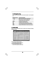
...Load Defaults Save and Exit Exit v02.54 (C) Copyright 1985-2005, American Megatrends, Inc. Main Advanced BIOS SETUP UTILITY H/W Monitor Boot System Overview System Time System Date [14:00:09] [Tue 02/12/2008] BIOS Version : 4Core1600Twins-P35D P1.00 Processor Type : Intel (R) Core(TM)2 Extreme CPU X9770 @ 3.20GHz (64bit) Processor Speed...description of each navigation key. 3.1.2Navigation Keys Please check the following table for all the settings To save changes and exit the BIOS SETUP UTILITY To jump to the Exit Screen or exit the current screen 3.2 Main Screen When you enter the...
...Load Defaults Save and Exit Exit v02.54 (C) Copyright 1985-2005, American Megatrends, Inc. Main Advanced BIOS SETUP UTILITY H/W Monitor Boot System Overview System Time System Date [14:00:09] [Tue 02/12/2008] BIOS Version : 4Core1600Twins-P35D P1.00 Processor Type : Intel (R) Core(TM)2 Extreme CPU X9770 @ 3.20GHz (64bit) Processor Speed...description of each navigation key. 3.1.2Navigation Keys Please check the following table for all the settings To save changes and exit the BIOS SETUP UTILITY To jump to the Exit Screen or exit the current screen 3.2 Main Screen When you enter the...

User Manual
Page 45
... Chipset Configuration ACPI Configuration IDE Configuration PCIPnP Configuration Floppy Configuration SuperIO Configuration USB Configuration Configure CPU Select Screen Select Item Enter Go to malfunction. 45 BIOS SETUP UTILITY Main Advanced H/W Monitor Boot Security Exit Advanced Settings WARNING : Setting wrong values in this section, you may set the configurations for the following...
... Chipset Configuration ACPI Configuration IDE Configuration PCIPnP Configuration Floppy Configuration SuperIO Configuration USB Configuration Configure CPU Select Screen Select Item Enter Go to malfunction. 45 BIOS SETUP UTILITY Main Advanced H/W Monitor Boot Security Exit Advanced Settings WARNING : Setting wrong values in this section, you may set the configurations for the following...
User Manual
Page 46
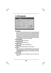
..., Inc. Please refer to adjust CPU frequency. If it shows "Unlocked", you will automatically enable the overclocking function when your CPU is enabled. 3.3.1CPU Configuration BIOS SETUP UTILITY Advanced CPU Configuration Overclock Mode CPU Frequency (MHz) PCIE Frequency (MHz) Boot Failure Guard Spread Spectrum [Auto] [400] [100] [Enabled] [Auto] Ratio Status...
..., Inc. Please refer to adjust CPU frequency. If it shows "Unlocked", you will automatically enable the overclocking function when your CPU is enabled. 3.3.1CPU Configuration BIOS SETUP UTILITY Advanced CPU Configuration Overclock Mode CPU Frequency (MHz) PCIE Frequency (MHz) Boot Failure Guard Spread Spectrum [Auto] [400] [100] [Enabled] [Auto] Ratio Status...

User Manual
Page 48
... module(s) inserted and assigns appropriate frequency automatically. Configuration options: [Auto], [3 DRAM Clocks], [4 DRAM Clocks], [5 DRAM Clocks] and [6 DRAM Clocks]. DRAM RAS# to [Enabled]. 3.3.2Chipset Configuration BIOS SETUP UTILITY Advanced Chipset Configuration Memory Remap Feature [Disabled] DRAM Frequency [Auto] Flexibility Option [Disabled] DRAM CAS# Latency [Auto] DRAM RAS# to CAS# Delay [Auto...
... module(s) inserted and assigns appropriate frequency automatically. Configuration options: [Auto], [3 DRAM Clocks], [4 DRAM Clocks], [5 DRAM Clocks] and [6 DRAM Clocks]. DRAM RAS# to [Enabled]. 3.3.2Chipset Configuration BIOS SETUP UTILITY Advanced Chipset Configuration Memory Remap Feature [Disabled] DRAM Frequency [Auto] Flexibility Option [Disabled] DRAM CAS# Latency [Auto] DRAM RAS# to CAS# Delay [Auto...

User Manual
Page 50
... resumes and the system starts to boot up when the power recovers. If [Power On] is selected, the AC/power remains off mode. 3.3.3 ACPI Configuration BIOS SETUP UTILITY Advanced ACPI Configuration Suspend To RAM Repost Video on STR Resume Restore on AC/Power Loss This allows you to set this item...
... resumes and the system starts to boot up when the power recovers. If [Power On] is selected, the AC/power remains off mode. 3.3.3 ACPI Configuration BIOS SETUP UTILITY Advanced ACPI Configuration Suspend To RAM Repost Video on STR Resume Restore on AC/Power Loss This allows you to set this item...

User Manual
Page 51
ACPI HPET Table Use this motherboard to submit Windows® VistaTM certification. 3.3.4IDE Configuration BIOS SETUP UTILITY Advanced IDE Configuration SATAII Configuration Configure SATAII as ", you plan to [AHCI] or [IDE] mode. If native OS (Windows 2000 / XP) is [Disabled]. ...
ACPI HPET Table Use this motherboard to submit Windows® VistaTM certification. 3.3.4IDE Configuration BIOS SETUP UTILITY Advanced IDE Configuration SATAII Configuration Configure SATAII as ", you plan to [AHCI] or [IDE] mode. If native OS (Windows 2000 / XP) is [Disabled]. ...

User Manual
Page 52
...], and [ARMD]. [Not Installed]: Select [Not Installed] to disable the use a disk utility, such as MO. After selecting the hard disk information into BIOS, use of device connected to active. [CD/DVD]: This is used for IDE ARMD (ATAPI Removable Media Device), such as FDISK, to disable the LBA... Use this item is necessary so that you specify. Block (Multi-Sector Transfer) The default value of the IDE device that you specify. BIOS SETUP UTILITY Advanced Primary IDE Master Device Vendor Size LBA Mode Block Mode PIO Mode Async DMA Ultra DMA S.M.A.R.T. TYPE Use this item to ...
...], and [ARMD]. [Not Installed]: Select [Not Installed] to disable the use a disk utility, such as MO. After selecting the hard disk information into BIOS, use of device connected to active. [CD/DVD]: This is used for IDE ARMD (ATAPI Removable Media Device), such as FDISK, to disable the LBA... Use this item is necessary so that you specify. Block (Multi-Sector Transfer) The default value of the IDE device that you specify. BIOS SETUP UTILITY Advanced Primary IDE Master Device Vendor Size LBA Mode Block Mode PIO Mode Async DMA Ultra DMA S.M.A.R.T. TYPE Use this item to ...

User Manual
Page 53
...-Monitoring, Analysis, and Reporting Technology) feature. PCI Latency Timer The default value is recommended to maximize the IDE hard disk data transfer rate. 3.3.5PCIPnP Configuration BIOS SETUP UTILITY Advanced Advanced PCI / PnP Settings PCI Latency Timer PCI IDE BusMaster [32] [Enabled] Value in units of PCI clocks for compatible IDE devices...
...-Monitoring, Analysis, and Reporting Technology) feature. PCI Latency Timer The default value is recommended to maximize the IDE hard disk data transfer rate. 3.3.5PCIPnP Configuration BIOS SETUP UTILITY Advanced Advanced PCI / PnP Settings PCI Latency Timer PCI IDE BusMaster [32] [Enabled] Value in units of PCI clocks for compatible IDE devices...


