User Manual
Page 6
LGA 775 for Intel® CoreTM 2 Extreme / CoreTM 2 Quad / CoreTM 2 Duo / Pentium® Dual Core / Celeron®, supporting Penryn Quad Core Yorkfield and Dual Core Wolfdale processors - ... x16 slot - 1 x AGI Express slot (PCI Express x4) - 3 x PCI slots - 7.1 CH Windows® VistaTM Premium Level HD Audio (ALC888 Audio Codec) - Supports Wake-On-LAN ASRock 8CH_eSATAII I /O - Compatible with all FSB1600/1333/1066/800MHz CPUs (see CAUTION 5) - Supports EM64T CPU - Support DDR3 1333/1066/800 non-ECC, un-buffered memory (see...
LGA 775 for Intel® CoreTM 2 Extreme / CoreTM 2 Quad / CoreTM 2 Duo / Pentium® Dual Core / Celeron®, supporting Penryn Quad Core Yorkfield and Dual Core Wolfdale processors - ... x16 slot - 1 x AGI Express slot (PCI Express x4) - 3 x PCI slots - 7.1 CH Windows® VistaTM Premium Level HD Audio (ALC888 Audio Codec) - Supports Wake-On-LAN ASRock 8CH_eSATAII I /O - Compatible with all FSB1600/1333/1066/800MHz CPUs (see CAUTION 5) - Supports EM64T CPU - Support DDR3 1333/1066/800 non-ECC, un-buffered memory (see...

User Manual
Page 11
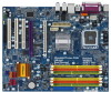
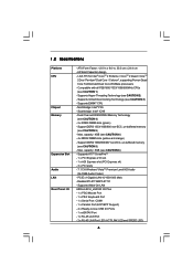
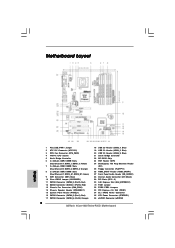
...Super I/O AUDIO CODEC PCIE1 RAID FSB2 1 1 FSB3 FSB1 1 AGI_EXPRESS1 PCI1 PCI EXPRESS 4Mb BIOS PCI2 1 WIFI PCI3 CD1 HD_AUDIO1 HDMI_SPDIF1 1 1 FLOPPY1 IR1 1 4Core1600Twins-P35D FSB1600 Dual Channel Quad Core CPU IDE1 1 CLRCMOS1 CMOS Battery Intel ICH9 SATAII CHA_FAN1 SATAII_5 (Port4) SATAII_6 (Port5) SATAII_1 (Port0) USB8_9 1 USB4_5 1 USB6_7 1... 15 27 26 25 24 23 22 2120 191817 16 1 PS2_USB_PWR1 Jumper 2 ATX 12V Connector (ATX12V1) 3 CPU Fan Connector (CPU_FAN1) 4 775-Pin CPU Socket 5 North Bridge Controller 6 2 x 240-pin DDR2 DIMM Slots (Dual Channel A: DDRII_1, DDRII_3;
...Super I/O AUDIO CODEC PCIE1 RAID FSB2 1 1 FSB3 FSB1 1 AGI_EXPRESS1 PCI1 PCI EXPRESS 4Mb BIOS PCI2 1 WIFI PCI3 CD1 HD_AUDIO1 HDMI_SPDIF1 1 1 FLOPPY1 IR1 1 4Core1600Twins-P35D FSB1600 Dual Channel Quad Core CPU IDE1 1 CLRCMOS1 CMOS Battery Intel ICH9 SATAII CHA_FAN1 SATAII_5 (Port4) SATAII_6 (Port5) SATAII_1 (Port0) USB8_9 1 USB4_5 1 USB6_7 1... 15 27 26 25 24 23 22 2120 191817 16 1 PS2_USB_PWR1 Jumper 2 ATX 12V Connector (ATX12V1) 3 CPU Fan Connector (CPU_FAN1) 4 775-Pin CPU Socket 5 North Bridge Controller 6 2 x 240-pin DDR2 DIMM Slots (Dual Channel A: DDRII_1, DDRII_3;
User Manual
Page 14
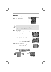
...please check if the CPU surface is unclean or if there is found. Step 2. Rotate the load lever to clear retention tab. Insert the 775-LAND CPU: Step 2-1. Step 2-2. Orient the CPU with black lines. Disengaging the lever by the edges where are marked with IHS (Integrated ...Heat Sink) up. Step 1-3. Pin1 orientation key notch orientation key notch Pin1 alignment key alignment key 775-LAND CPU 775-Pin Socket 14 black line black line Step 1-2. Locate Pin1 and the two orientation key notches. 2.3 CPU Installation For the installation of...
...please check if the CPU surface is unclean or if there is found. Step 2. Rotate the load lever to clear retention tab. Insert the 775-LAND CPU: Step 2-1. Step 2-2. Orient the CPU with black lines. Disengaging the lever by the edges where are marked with IHS (Integrated ...Heat Sink) up. Step 1-3. Pin1 orientation key notch orientation key notch Pin1 alignment key alignment key 775-LAND CPU 775-Pin Socket 14 black line black line Step 1-2. Locate Pin1 and the two orientation key notches. 2.3 CPU Installation For the installation of...
User Manual
Page 16
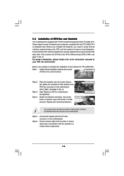
... the heatsink cannot be secured on the socket surface. Step 5. Step 2. Ensure fan cables are securely fastened and in good contact with 775-Pin socket that the CPU and the heatsink are oriented on side closest to the CPU fan connector on the motherboard. 2.4 Installation of ...of heatsink and cooling fan compliant with the CPU fan connector on the motherboard (CPU_FAN1, see page 11, No. 3). Ensure that supports Intel 775-LAND CPU. Apply thermal interface material onto center of your CPU fan and heatsink. Step 3. Step 4. Secure excess cable with tie-wrap to...
... the heatsink cannot be secured on the socket surface. Step 5. Step 2. Ensure fan cables are securely fastened and in good contact with 775-Pin socket that the CPU and the heatsink are oriented on side closest to the CPU fan connector on the motherboard. 2.4 Installation of ...of heatsink and cooling fan compliant with the CPU fan connector on the motherboard (CPU_FAN1, see page 11, No. 3). Ensure that supports Intel 775-LAND CPU. Apply thermal interface material onto center of your CPU fan and heatsink. Step 3. Step 4. Secure excess cable with tie-wrap to...
Quick Installation Guide
Page 2
Orange) 8 2 x 240-pin DDR3 DIMM Slots (Dual Channel C: DDR3_A1, DDR3_B1; Motherboard Layout English 1 PS2_USB_PWR1 Jumper 2 ATX 12V Connector (ATX12V1) 3 CPU Fan Connector (CPU_FAN1) 4 775-Pin CPU Socket 5 North Bridge Controller 6 2 x 240-pin DDR2 DIMM Slots (Dual Channel A: DDRII_1, DDRII_3; Yellow) 7 2 x 240-pin DDR2 DIMM Slots (Dual Channel B: DDRII_2, DDRII_4; ... Jumper 32 FSB2 / FSB3 Jumpers 33 PCI Express x16 Slot (PCIE1) 34 SLI / XFIRE Power Connector 35 ATX Power Connector (ATXPWR1) 36 eSATAII Connector (eSATAII) 2 ASRock 4Core1600Twins-P35D Motherboard
Orange) 8 2 x 240-pin DDR3 DIMM Slots (Dual Channel C: DDR3_A1, DDR3_B1; Motherboard Layout English 1 PS2_USB_PWR1 Jumper 2 ATX 12V Connector (ATX12V1) 3 CPU Fan Connector (CPU_FAN1) 4 775-Pin CPU Socket 5 North Bridge Controller 6 2 x 240-pin DDR2 DIMM Slots (Dual Channel A: DDRII_1, DDRII_3; Yellow) 7 2 x 240-pin DDR2 DIMM Slots (Dual Channel B: DDRII_2, DDRII_4; ... Jumper 32 FSB2 / FSB3 Jumpers 33 PCI Express x16 Slot (PCIE1) 34 SLI / XFIRE Power Connector 35 ATX Power Connector (ATXPWR1) 36 eSATAII Connector (eSATAII) 2 ASRock 4Core1600Twins-P35D Motherboard

Quick Installation Guide
Page 5
... Ports - 1 x eSATAII Port - 1 x RJ-45 LAN Port - 2 x RJ-45 LAN Port LED (ACT/LINK LED and SPEED LED) 5 ASRock 4Core1600Twins-P35D Motherboard English Dual Channel DDR3/DDR2 Memory Technology (see CAUTION 6) - Max. capacity: 8GB (see CAUTION 4) - 2 x DDR3 DIMM slots (green) - Supports Wake-On-LAN... ASRock 8CH_eSATAII I /O - Northbridge: Intel® P35 - Max. PCIE x1 Gigabit LAN 10/100/1000 Mb/s - LGA 775 for Intel® CoreTM 2 Extreme / CoreTM 2 Quad / CoreTM 2 Duo / Pentium® Dual Core /...
... Ports - 1 x eSATAII Port - 1 x RJ-45 LAN Port - 2 x RJ-45 LAN Port LED (ACT/LINK LED and SPEED LED) 5 ASRock 4Core1600Twins-P35D Motherboard English Dual Channel DDR3/DDR2 Memory Technology (see CAUTION 6) - Max. capacity: 8GB (see CAUTION 4) - 2 x DDR3 DIMM slots (green) - Supports Wake-On-LAN... ASRock 8CH_eSATAII I /O - Northbridge: Intel® P35 - Max. PCIE x1 Gigabit LAN 10/100/1000 Mb/s - LGA 775 for Intel® CoreTM 2 Extreme / CoreTM 2 Quad / CoreTM 2 Duo / Pentium® Dual Core /...

Quick Installation Guide
Page 9
...To avoid damaging the motherboard components due to use a grounded wrist strap or touch a safety grounded object before you insert the 775-LAND CPU into the socket, please check if the CPU surface is unclean or if there is found. Whenever you install motherboard ...to qualify for Windows® VistaTM Premium 2008 logo. 2. Otherwise, the CPU will be seriously damaged. 9 ASRock 4Core1600Twins-P35D Motherboard Installation Pre-installation Precautions Take note of Intel 775-LAND CPU, please follow the steps below. CPU Memory VGA Celeron 420 1GB system memory (Premium) 512MB Single...
...To avoid damaging the motherboard components due to use a grounded wrist strap or touch a safety grounded object before you insert the 775-LAND CPU into the socket, please check if the CPU surface is unclean or if there is found. Whenever you install motherboard ...to qualify for Windows® VistaTM Premium 2008 logo. 2. Otherwise, the CPU will be seriously damaged. 9 ASRock 4Core1600Twins-P35D Motherboard Installation Pre-installation Precautions Take note of Intel 775-LAND CPU, please follow the steps below. CPU Memory VGA Celeron 420 1GB system memory (Premium) 512MB Single...
Quick Installation Guide
Page 10
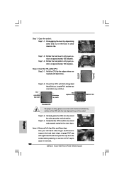
...the orient keys. Remove PnP Cap (Pick and Place Cap): Use your left hand index finger and thumb to assist in removal. 10 ASRock 4Core1600Twins-P35D Motherboard Step 1. Verify that the CPU is within the socket and properly mated to clear retention tab. Disengaging the lever by depressing down ...and out on center of the socket. Insert the 775-LAND CPU: Step 2-1. Pin1 orientation key notch orientation key notch Pin1 alignment key alignment key 775-LAND CPU 775-Pin Socket For proper inserting, please ensure to match the two orientation key notches of...
...the orient keys. Remove PnP Cap (Pick and Place Cap): Use your left hand index finger and thumb to assist in removal. 10 ASRock 4Core1600Twins-P35D Motherboard Step 1. Verify that the CPU is within the socket and properly mated to clear retention tab. Disengaging the lever by depressing down ...and out on center of the socket. Insert the 775-LAND CPU: Step 2-1. Pin1 orientation key notch orientation key notch Pin1 alignment key alignment key 775-LAND CPU 775-Pin Socket For proper inserting, please ensure to match the two orientation key notches of...
Quick Installation Guide
Page 11
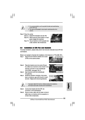
... 6. Connect fan header with remaining fasteners. While pressing down the fasteners without rotating them clockwise, the heatsink cannot be placed if returning the motherboard for 775-LAND CPU. Ensure fan cables are oriented on side closest to install and lock. Rotate the fastener clockwise, then press down on the motherboard. This... on load plate, engage the load lever. Step 2. Step 3. Place the heatsink onto the socket. Align fasteners with fan operation or contact other components. 11 ASRock 4Core1600Twins-P35D Motherboard English
... 6. Connect fan header with remaining fasteners. While pressing down the fasteners without rotating them clockwise, the heatsink cannot be placed if returning the motherboard for 775-LAND CPU. Ensure fan cables are oriented on side closest to install and lock. Rotate the fastener clockwise, then press down on the motherboard. This... on load plate, engage the load lever. Step 2. Step 3. Place the heatsink onto the socket. Align fasteners with fan operation or contact other components. 11 ASRock 4Core1600Twins-P35D Motherboard English