User Manual
Page 2
... by any means, except duplication of documentation by the purchaser for backup purpose, without written consent of ASRock Inc. ASRock assumes no event shall ASRock, its directors, officers, employees, or agents be liable for any interference received, including interference that may...www.asrock.com 2 Products and corporate names appearing in advance. "Perchlorate Material-special handling may not be constructed as a commitment by the California Legislature. When you discard the Lithium battery in California, USA, please follow the related regulations in this motherboard contains...
... by any means, except duplication of documentation by the purchaser for backup purpose, without written consent of ASRock Inc. ASRock assumes no event shall ASRock, its directors, officers, employees, or agents be liable for any interference received, including interference that may...www.asrock.com 2 Products and corporate names appearing in advance. "Perchlorate Material-special handling may not be constructed as a commitment by the California Legislature. When you discard the Lithium battery in California, USA, please follow the related regulations in this motherboard contains...
User Manual
Page 3
Contents 1 Introduction 5 1.1 Package Contents 5 1.2 Specifications 6 1.3 Minimum Hardware Requirement Table for Windows® VistaTM Premium 2008 and Basic Logo 10 1.4 Motherboard Layout 11 1.5 ASRock 8CH_eSATAII I/O Plus 12 2 Installation 13 2.1 Screw Holes 13 2.2 Pre-installation Precautions 13 2.3 CPU Installation 14 2.4 Installation of Heatsink and CPU fan 16 2.5 Installation of Memory ...
Contents 1 Introduction 5 1.1 Package Contents 5 1.2 Specifications 6 1.3 Minimum Hardware Requirement Table for Windows® VistaTM Premium 2008 and Basic Logo 10 1.4 Motherboard Layout 11 1.5 ASRock 8CH_eSATAII I/O Plus 12 2 Installation 13 2.1 Screw Holes 13 2.2 Pre-installation Precautions 13 2.3 CPU Installation 14 2.4 Installation of Heatsink and CPU fan 16 2.5 Installation of Memory ...
User Manual
Page 5
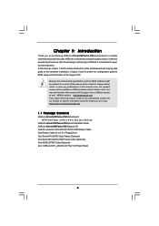
..., chapter 1 and 2 contain introduction of the Support CD. You may find the latest VGA cards and CPU support lists on ASRock website without notice. www.asrock.com/support/index.asp 1.1 Package Contents ASRock 4Core1600Twins-P35 Motherboard (ATX Form Factor: 12.0-in x 9.6-in Floppy Drive Two Serial ATA (SATA) Data Cables (Optional) One Serial ATA (SATA) HDD...
..., chapter 1 and 2 contain introduction of the Support CD. You may find the latest VGA cards and CPU support lists on ASRock website without notice. www.asrock.com/support/index.asp 1.1 Package Contents ASRock 4Core1600Twins-P35 Motherboard (ATX Form Factor: 12.0-in x 9.6-in Floppy Drive Two Serial ATA (SATA) Data Cables (Optional) One Serial ATA (SATA) HDD...
User Manual
Page 8
...1066 and DDR3 1333 memory modules will run at DDR3 960 if you adopt a DDR2 1066 memory module. CPU or FSB1066-CPU on this motherboard, it will operate in the BIOS, applying Untied Overclocking Technology, or using the thirdparty overclocking tools. FSB1600-CPU will run at your PC ...in overclocking mode. * When you need to adjust the jumpers. Please read the installation guide of memory modules on this motherboard, please remove the AC power cord from your own risk and expense. We are not responsible for proper jumper settings. 8 Please refer to...
...1066 and DDR3 1333 memory modules will run at DDR3 960 if you adopt a DDR2 1066 memory module. CPU or FSB1066-CPU on this motherboard, it will operate in the BIOS, applying Untied Overclocking Technology, or using the thirdparty overclocking tools. FSB1600-CPU will run at your PC ...in overclocking mode. * When you need to adjust the jumpers. Please read the installation guide of memory modules on this motherboard, please remove the AC power cord from your own risk and expense. We are not responsible for proper jumper settings. 8 Please refer to...
User Manual
Page 9
...eSATAII installation procedures. 10. Please visit our website for system usage under Windows® 2000. ASRock website: http://www.asrock.com 13. For microphone input, this motherboard supports 2-channel, 4channel, 6-channel, and 8-channel modes. WiFi header supports WiFi+AP function ...SATAII Hard Disk Setup Guide" on page 33 for USB 2.0 works fine under Windows® environment. ASRock website http://www.asrock.com 12. This motherboard supports eSATAII interface, the external SATAII specification. AHCI function is detected, the system will automatically shutdown. ...
...eSATAII installation procedures. 10. Please visit our website for system usage under Windows® 2000. ASRock website: http://www.asrock.com 13. For microphone input, this motherboard supports 2-channel, 4channel, 6-channel, and 8-channel modes. WiFi header supports WiFi+AP function ...SATAII Hard Disk Setup Guide" on page 33 for USB 2.0 works fine under Windows® environment. ASRock website http://www.asrock.com 12. This motherboard supports eSATAII interface, the external SATAII specification. AHCI function is detected, the system will automatically shutdown. ...
User Manual
Page 10
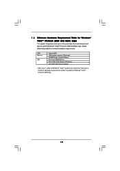
... Premium 2008 logo. 10 1.3 Minimum Hardware Requirement Table for Windows® VistaTM Premium 2008 and Basic Logo For system integrators and users who purchase this motherboard and plan to qualify for minimum hardware requirements.
... Premium 2008 logo. 10 1.3 Minimum Hardware Requirement Table for Windows® VistaTM Premium 2008 and Basic Logo For system integrators and users who purchase this motherboard and plan to qualify for minimum hardware requirements.

User Manual
Page 11
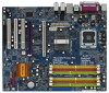
...pin DDR2 DIMM Slots (Dual Channel B: DDRII_2, DDRII_4; Orange) 8 2 x 240-pin DDR3 DIMM Slots (Dual Channel C: DDR3_A1, DDR3_B1; 1.4 Motherboard Layout 1 2 34 5 24.4cm (9.6 in) 67 8 PS2 Mouse PS2 Keyboard RoHS Yorkfield Wolfdale DDR2 1066 DDR3 1333 36 COM1 1 PS2_USB_PWR1 ATX12V1 ... FSB2 1 1 FSB3 FSB1 1 AGI_EXPRESS1 PCI1 PCI EXPRESS 4Mb BIOS PCI2 1 WIFI PCI3 CD1 HD_AUDIO1 HDMI_SPDIF1 1 1 FLOPPY1 IR1 1 4Core1600Twins-P35 FSB1600 Dual Channel Quad Core CPU IDE1 1 CLRCMOS1 CMOS Battery Intel ICH9 SATAII CHA_FAN1 SATAII_5 (Port4) SATAII_6 (Port5) SATAII_1 (Port0) USB8_9...
...pin DDR2 DIMM Slots (Dual Channel B: DDRII_2, DDRII_4; Orange) 8 2 x 240-pin DDR3 DIMM Slots (Dual Channel C: DDR3_A1, DDR3_B1; 1.4 Motherboard Layout 1 2 34 5 24.4cm (9.6 in) 67 8 PS2 Mouse PS2 Keyboard RoHS Yorkfield Wolfdale DDR2 1066 DDR3 1333 36 COM1 1 PS2_USB_PWR1 ATX12V1 ... FSB2 1 1 FSB3 FSB1 1 AGI_EXPRESS1 PCI1 PCI EXPRESS 4Mb BIOS PCI2 1 WIFI PCI3 CD1 HD_AUDIO1 HDMI_SPDIF1 1 1 FLOPPY1 IR1 1 4Core1600Twins-P35 FSB1600 Dual Channel Quad Core CPU IDE1 1 CLRCMOS1 CMOS Battery Intel ICH9 SATAII CHA_FAN1 SATAII_5 (Port4) SATAII_6 (Port5) SATAII_1 (Port0) USB8_9...
User Manual
Page 13
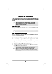
.... 2.1 Screw Holes Place screws into it on the carpet or the like. Failure to do so may damage the motherboard. 2.2 Pre-installation Precautions Take note of your motherboard directly on a grounded antistatic pad or in the bag that the power is switched off or the power cord is ...an ATX form factor (12.0" x 9.6", 30.5 x 24.4 cm) motherboard. Also remember to do so may cause physical injuries to you install motherboard components or change any component. 2. Failure to use a grounded wrist strap or touch a safety grounded object before you ...
.... 2.1 Screw Holes Place screws into it on the carpet or the like. Failure to do so may damage the motherboard. 2.2 Pre-installation Precautions Take note of your motherboard directly on a grounded antistatic pad or in the bag that the power is switched off or the power cord is ...an ATX form factor (12.0" x 9.6", 30.5 x 24.4 cm) motherboard. Also remember to do so may cause physical injuries to you install motherboard components or change any component. 2. Failure to use a grounded wrist strap or touch a safety grounded object before you ...
User Manual
Page 15
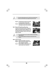
... load lever. 15 For proper inserting, please ensure to handle and avoid kicking off the PnP cap. 2. This cap must be placed if returning the motherboard for after service. Close the socket: Step 4-1.
... load lever. 15 For proper inserting, please ensure to handle and avoid kicking off the PnP cap. 2. This cap must be placed if returning the motherboard for after service. Close the socket: Step 4-1.

User Manual
Page 16
...the heatsink cannot be secured on fastener caps with thumb to dissipate heat. Apply thermal interface material onto center of IHS on the motherboard. Place the heatsink onto the socket. Align fasteners with remaining fasteners. Ensure that supports Intel 775-LAND CPU. Please adopt the ...and the heatsink to the CPU_FAN connector (CPU_FAN1, see page 11, No. 3). Step 5. 2.4 Installation of CPU Fan and Heatsink This motherboard is an example to ensure cable does not interfere with fan operation or contact other . Secure excess cable with tie-wrap to illustrate the...
...the heatsink cannot be secured on fastener caps with thumb to dissipate heat. Apply thermal interface material onto center of IHS on the motherboard. Place the heatsink onto the socket. Align fasteners with remaining fasteners. Ensure that supports Intel 775-LAND CPU. Please adopt the ...and the heatsink to the CPU_FAN connector (CPU_FAN1, see page 11, No. 3). Step 5. 2.4 Installation of CPU Fan and Heatsink This motherboard is an example to ensure cable does not interfere with fan operation or contact other . Secure excess cable with tie-wrap to illustrate the...
User Manual
Page 17
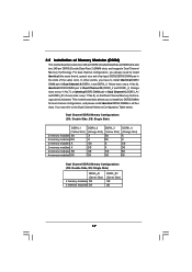
...see p.11 No.6), identical DDR2 DIMM pair in all four slots. see p.11 No.8), so that Dual Channel Memory Technology can be activated. This motherboard also allows you to the Dual Channel Memory Configuration Table below. Yellow slots; Dual Channel DDR2 Memory Configurations (DS: Double Side, SS: Single Side... A (DDRII_1 and DDRII_3; In other words, you always need to install identical DDR2 DIMM pair in the slots of Memory Modules (DIMM) This motherboard provides four 240-pin DDR2 (Double Data Rate 2) DIMM slots and two 240-pin DDR3 (Double Data Rate 3) DIMM slots, and supports Dual ...
...see p.11 No.6), identical DDR2 DIMM pair in all four slots. see p.11 No.8), so that Dual Channel Memory Technology can be activated. This motherboard also allows you to the Dual Channel Memory Configuration Table below. Yellow slots; Dual Channel DDR2 Memory Configurations (DS: Double Side, SS: Single Side... A (DDRII_1 and DDRII_3; In other words, you always need to install identical DDR2 DIMM pair in the slots of Memory Modules (DIMM) This motherboard provides four 240-pin DDR2 (Double Data Rate 2) DIMM slots and two 240-pin DDR3 (Double Data Rate 3) DIMM slots, and supports Dual ...
User Manual
Page 18
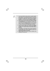
... compatibility and reliability, it is unable to activate the Dual Channel Memory Technology. 3. DDR2 and DDR3 memory modules cannot be installed on this motherboard, it is unable to install a DDR3 memory module into DDR2 slot or install a DDR2 memory module into DDR3 slot; If only one ...for example, installing a pair of memory modules in the slots of yellow slots (DDRII_1 and DDRII_3), or in the DDR2 DIMM slots on this motherboard and DIMM may be damaged. 5. In other words, install them in DDRII_1 and DDRII_2, it is unable to activate the Dual Channel Memory Technology...
... compatibility and reliability, it is unable to activate the Dual Channel Memory Technology. 3. DDR2 and DDR3 memory modules cannot be installed on this motherboard, it is unable to install a DDR3 memory module into DDR2 slot or install a DDR2 memory module into DDR3 slot; If only one ...for example, installing a pair of memory modules in the slots of yellow slots (DDRII_1 and DDRII_3), or in the DDR2 DIMM slots on this motherboard and DIMM may be damaged. 5. In other words, install them in DDRII_1 and DDRII_2, it is unable to activate the Dual Channel Memory Technology...
User Manual
Page 19
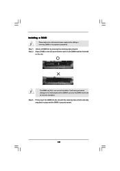
.... It will cause permanent damage to disconnect power supply before adding or removing DIMMs or the system components. Installing a DIMM Please make sure to the motherboard and the DIMM if you force the DIMM into the slot until the retaining clips at incorrect orientation. Step 1. Step 2. Align a DIMM on the slot...
.... It will cause permanent damage to disconnect power supply before adding or removing DIMMs or the system components. Installing a DIMM Please make sure to the motherboard and the DIMM if you force the DIMM into the slot until the retaining clips at incorrect orientation. Step 1. Step 2. Align a DIMM on the slot...
User Manual
Page 20
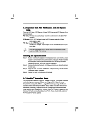
...read the documentation of performance and image quality in a single PC. Align the card connector with screws. 2.7 CrossFireTM Operation Guide This motherboard supports CrossFireTM feature. Fasten the card to the chassis with the slot and press firmly until the card is used to install only one... Step 2. PCI slots: PCI slots are 3 PCI slots, 1 PCI Express slot, and 1 AGI Express slot (PCI Express x4) on this motherboard, please install it on the slot. Before installing the expansion card, please make necessary hardware settings for PCI Express cards with Service Pack 2 and ...
...read the documentation of performance and image quality in a single PC. Align the card connector with screws. 2.7 CrossFireTM Operation Guide This motherboard supports CrossFireTM feature. Fasten the card to the chassis with the slot and press firmly until the card is used to install only one... Step 2. PCI slots: PCI slots are 3 PCI slots, 1 PCI Express slot, and 1 AGI Express slot (PCI Express x4) on this motherboard, please install it on the slot. Before installing the expansion card, please make necessary hardware settings for PCI Express cards with Service Pack 2 and ...
User Manual
Page 21
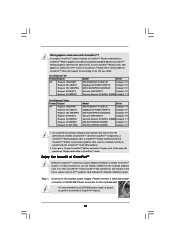
... released or will release in CrossFireTM mode. If you install. Step 1. Connect to SLI/XFIRE Power connector on this motherboard. For Windows® XP Vendor Chipset ATI Radeon HD2900XT Radeon HD 2600XT Radeon HD 2600PRO Radeon X1950XTX Radeon X1950PRO Model...11 MSI RX1600PRO-TD256E Catalyst 7.3 MSI RX1300PRO-TD256E Catalyst 7.3 1. All three CrossFireTM components, a CrossFireTM Ready graphics card, a CrossFireTM Ready motherboard and a CrossFireTM Edition co-processor graphics card, must be installed correctly to benefit from the CrossFireTM multi-GPU platform. 2. It is ...
... released or will release in CrossFireTM mode. If you install. Step 1. Connect to SLI/XFIRE Power connector on this motherboard. For Windows® XP Vendor Chipset ATI Radeon HD2900XT Radeon HD 2600XT Radeon HD 2600PRO Radeon X1950XTX Radeon X1950PRO Model...11 MSI RX1600PRO-TD256E Catalyst 7.3 MSI RX1300PRO-TD256E Catalyst 7.3 1. All three CrossFireTM components, a CrossFireTM Ready graphics card, a CrossFireTM Ready motherboard and a CrossFireTM Edition co-processor graphics card, must be installed correctly to benefit from the CrossFireTM multi-GPU platform. 2. It is ...
User Manual
Page 22
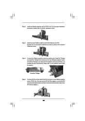
... the Radeon graphics card on the top of Radeon graphics cards. (CrossFireTM Bridge is provided with the graphics card you purchase, not bundled with this motherboard. For the proper installation procedures, please refer to section "Expansion Slots". For the proper installation procedures, please refer to section "Expansion Slots". Connect two Radeon...
... the Radeon graphics card on the top of Radeon graphics cards. (CrossFireTM Bridge is provided with the graphics card you purchase, not bundled with this motherboard. For the proper installation procedures, please refer to section "Expansion Slots". For the proper installation procedures, please refer to section "Expansion Slots". Connect two Radeon...
User Manual
Page 24
..., please refer to the document at the following path in "ATI Catalyst Control Center" is used only for updates and details. 2.8 Surround Display Feature This motherboard supports Surround Display upgrade. After restarting your computer, please confirm whether the option "Enable CrossFireTM" in the Support CD: ..\ Surround Display Information 24 Your computer...
..., please refer to the document at the following path in "ATI Catalyst Control Center" is used only for updates and details. 2.8 Surround Display Feature This motherboard supports Surround Display upgrade. After restarting your computer, please confirm whether the option "Enable CrossFireTM" in the Support CD: ..\ Surround Display Information 24 Your computer...
User Manual
Page 26
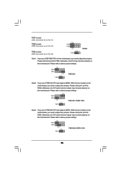
... 2_3 1_2 FSB1 FSB1066 / DDR2 1066 26 Please refer to adjust the jumpers. Otherwise, the CPU and memory module may not work properly on this motherboard. FSB1 Jumper (FSB1, 3-pin jumper, see p.11 No. 31) FSB2 Jumper (FSB2, 5-pin jumper, see p.11 No. 32) FSB3 Jumper (FSB3, 5-pin jumper, see p....11 No. 32) 1_2 FSB2 FSB3 1_2 1_2 FSB1 Default Note1: If you use a FSB1600-CPU on this motherboard. Please refer to below jumper settings. 4_5 FSB2 FSB3 1_2 1_2 FSB1 FSB1333 / DDR2 1066 Note3: If you use a FSB1333-CPU and adopt a DDR2 1066...
... 2_3 1_2 FSB1 FSB1066 / DDR2 1066 26 Please refer to adjust the jumpers. Otherwise, the CPU and memory module may not work properly on this motherboard. FSB1 Jumper (FSB1, 3-pin jumper, see p.11 No. 31) FSB2 Jumper (FSB2, 5-pin jumper, see p.11 No. 32) FSB3 Jumper (FSB3, 5-pin jumper, see p....11 No. 32) 1_2 FSB2 FSB3 1_2 1_2 FSB1 Default Note1: If you use a FSB1600-CPU on this motherboard. Please refer to below jumper settings. 4_5 FSB2 FSB3 1_2 1_2 FSB1 FSB1333 / DDR2 1066 Note3: If you use a FSB1333-CPU and adopt a DDR2 1066...
User Manual
Page 27
... current SATAII interface allows up to support eSATAII device. Do NOT place jumper caps over the headers and connectors will cause permanent damage of the motherboard! Serial ATAII Connectors (SATAII_1 (Port0): see p.11, No. 12) (SATAII_2 (Port1): SATAII_5 (Port4) SATAII_1 (Port0) see p.11, No. 16) (SATAII_5 (Port4): see ... of the connector. Primary IDE connector (Blue) (39-pin IDE1, see p.11 No. 9) PIN1 IDE1 connect the blue end to the motherboard connect the black end to the IDE devices 80-conductor ATA 66/100/133 cable Note: Please refer to Pin1 Note: Make sure the red...
... current SATAII interface allows up to support eSATAII device. Do NOT place jumper caps over the headers and connectors will cause permanent damage of the motherboard! Serial ATAII Connectors (SATAII_1 (Port0): see p.11, No. 12) (SATAII_2 (Port1): SATAII_5 (Port4) SATAII_1 (Port0) see p.11, No. 16) (SATAII_5 (Port4): see ... of the connector. Primary IDE connector (Blue) (39-pin IDE1, see p.11 No. 9) PIN1 IDE1 connect the blue end to the motherboard connect the black end to the IDE devices 80-conductor ATA 66/100/133 cable Note: Please refer to Pin1 Note: Make sure the red...

User Manual
Page 28
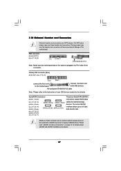
... power supply. You can support two USB 2.0 ports. 28 Besides four default USB 2.0 ports on the I/O panel, there are three USB 2.0 headers on this motherboard. eSATAII Connector (eSATAII: see p.11, No. 36) Serial ATA (SATA) Data Cable (Optional) eSATAII Serial ATA (SATA) Power Cable (Optional) connect to...connect SATAII_6 (Port5) connector and eSATAII connector. Either end of the SATA data cable can be connected to the power connector on this motherboard. Then connect the white end of SATA power cable to the power connector of SATA power cable to the SATA / SATAII hard disk...
... power supply. You can support two USB 2.0 ports. 28 Besides four default USB 2.0 ports on the I/O panel, there are three USB 2.0 headers on this motherboard. eSATAII Connector (eSATAII: see p.11, No. 36) Serial ATA (SATA) Data Cable (Optional) eSATAII Serial ATA (SATA) Power Cable (Optional) connect to...connect SATAII_6 (Port5) connector and eSATAII connector. Either end of the SATA data cable can be connected to the power connector on this motherboard. Then connect the white end of SATA power cable to the power connector of SATA power cable to the SATA / SATAII hard disk...

