
User Manual
Page 2
... are used only for any errors or omissions that may cause undesired operation. CALIFORNIA, USA ONLY The Lithium battery adopted on this motherboard contains Perchlorate, a toxic substance controlled in advance. When you discard the Lithium battery in California, USA, please follow the related... in Perchlorate Best Management Practices (BMP) regulations passed by the California Legislature. With respect to the contents of this manual, ASRock does not provide warranty of any kind, either expressed or implied, including but not limited to the implied warranties or conditions of...
... are used only for any errors or omissions that may cause undesired operation. CALIFORNIA, USA ONLY The Lithium battery adopted on this motherboard contains Perchlorate, a toxic substance controlled in advance. When you discard the Lithium battery in California, USA, please follow the related... in Perchlorate Best Management Practices (BMP) regulations passed by the California Legislature. With respect to the contents of this manual, ASRock does not provide warranty of any kind, either expressed or implied, including but not limited to the implied warranties or conditions of...
User Manual
Page 3
Contents 1 Introduction 5 1.1 Package Contents 5 1.2 Specifications 6 1.3 Minimum Hardware Requirement Table for Windows® VistaTM Premium 2007 and Basic Logo 9 1.4 Motherboard Layout 10 1.5 ASRock 6CH I/O 11 2 Installation 12 2.1 Screw Holes 12 2.2 Pre-installation Precautions 12 2.3 CPU Installation 13 2.4 Installation of Heatsink and CPU fan 15 2.5 Installation of Memory Modules (...
Contents 1 Introduction 5 1.1 Package Contents 5 1.2 Specifications 6 1.3 Minimum Hardware Requirement Table for Windows® VistaTM Premium 2007 and Basic Logo 9 1.4 Motherboard Layout 10 1.5 ASRock 6CH I/O 11 2 Installation 12 2.1 Screw Holes 12 2.2 Pre-installation Precautions 12 2.3 CPU Installation 13 2.4 Installation of Heatsink and CPU fan 15 2.5 Installation of Memory Modules (...
User Manual
Page 5
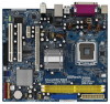
...1 and 2 contain introduction of this manual will be subject to the hardware installation. www.asrock.com/support/index.asp 1.1 Package Contents ASRock 4Core1600-D800 Motherboard (Micro ATX Form Factor: 9.6-in x 8.4-in Floppy Drive One Serial ATA (SATA) ...cm) ASRock 4Core1600-D800 Quick Installation Guide ASRock 4Core1600-D800 Support CD One 80-conductor Ultra ATA 66/100 IDE Ribbon Cable One Ribbon Cable for purchasing ASRock 4Core1600-D800 motherboard, a reliable motherboard produced under ASRock's consistently stringent quality control. In case any modifications of the motherboard and...
...1 and 2 contain introduction of this manual will be subject to the hardware installation. www.asrock.com/support/index.asp 1.1 Package Contents ASRock 4Core1600-D800 Motherboard (Micro ATX Form Factor: 9.6-in x 8.4-in Floppy Drive One Serial ATA (SATA) ...cm) ASRock 4Core1600-D800 Quick Installation Guide ASRock 4Core1600-D800 Support CD One 80-conductor Ultra ATA 66/100 IDE Ribbon Cable One Ribbon Cable for purchasing ASRock 4Core1600-D800 motherboard, a reliable motherboard produced under ASRock's consistently stringent quality control. In case any modifications of the motherboard and...
User Manual
Page 8
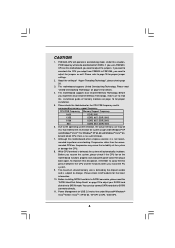
...for the latest information. 10. Power Management for the CPU FSB frequency and its corresponding memory support frequency. This motherboard supports Untied Overclocking Technology. You can also connect SATA hard disk to the operating system limitation, the actual memory ... cause the instability of "Hyper Threading Technology", please check page 28. 3. CAUTION! 1. Please refer to SATAII mode. This motherboard supports Dual Channel Memory Technology. bit with 64-bit CPU, there is detected, the system will automatically shutdown. Before installing SATAII...
...for the latest information. 10. Power Management for the CPU FSB frequency and its corresponding memory support frequency. This motherboard supports Untied Overclocking Technology. You can also connect SATA hard disk to the operating system limitation, the actual memory ... cause the instability of "Hyper Threading Technology", please check page 28. 3. CAUTION! 1. Please refer to SATAII mode. This motherboard supports Dual Channel Memory Technology. bit with 64-bit CPU, there is detected, the system will automatically shutdown. Before installing SATAII...
User Manual
Page 9
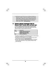
...11g or WiFi-802.11n module, an easy-to-use external graphics card on this motherboard and plan to qualify for Windows® VistaTM Premium 2007 logo. 9 12. ASRock website http://www.asrock.com 1 . 3 Minimum Hardware Requirement Table for Windows® VistaTM Premium 2007 ...and Basic Logo For system integrators and users who purchase this motherboard, please refer to Premium Discrete requirement at http://www.asrock.com * After June 1, 2007, all Windows® VistaTM systems are required to meet above minimum hardware ...
...11g or WiFi-802.11n module, an easy-to-use external graphics card on this motherboard and plan to qualify for Windows® VistaTM Premium 2007 logo. 9 12. ASRock website http://www.asrock.com 1 . 3 Minimum Hardware Requirement Table for Windows® VistaTM Premium 2007 ...and Basic Logo For system integrators and users who purchase this motherboard, please refer to Premium Discrete requirement at http://www.asrock.com * After June 1, 2007, all Windows® VistaTM systems are required to meet above minimum hardware ...
User Manual
Page 10
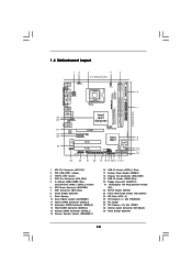
1.4 Motherboard Layout 12 3 4 5 21.3cm (8.4 in) 1 PS2_USB_PWR1 CPU_FAN1 PS2 Mouse PS2 Keyboard Wolfdale Yorkfield Dual Channel DDR2 800 AT X P W R 1 PARALLEL PORT COM1 29 28 27 26 ... 24 Top: Line In Center: Line Out Bottom: Mic In AT X 1 2 V 1 DDRII_2 (64 bit, 240-pin module) DDRII_1 (64 bit, 240-pin module) VGA1 IDE1 4Core1600-D800 Quad Core CPU FSB1600 USB 2.0 T: USB2 B: USB3 USB 2.0 T: USB0 B: USB1 Top: RJ-45 AUDIO CODEC CD1 Intel G31 Chipset PCIE1 LAN PHY FD 1 PCIE2/DE...
1.4 Motherboard Layout 12 3 4 5 21.3cm (8.4 in) 1 PS2_USB_PWR1 CPU_FAN1 PS2 Mouse PS2 Keyboard Wolfdale Yorkfield Dual Channel DDR2 800 AT X P W R 1 PARALLEL PORT COM1 29 28 27 26 ... 24 Top: Line In Center: Line Out Bottom: Mic In AT X 1 2 V 1 DDRII_2 (64 bit, 240-pin module) DDRII_1 (64 bit, 240-pin module) VGA1 IDE1 4Core1600-D800 Quad Core CPU FSB1600 USB 2.0 T: USB2 B: USB3 USB 2.0 T: USB0 B: USB1 Top: RJ-45 AUDIO CODEC CD1 Intel G31 Chipset PCIE1 LAN PHY FD 1 PCIE2/DE...

User Manual
Page 12
... holes indicated by the edges and do so may cause severe damage to unplug the power cord before installing or removing the motherboard. Failure to the chassis. Chapter 2 Installation 4Core1600-D800 is detached from the wall socket before touching any component, ensure that comes with the component. Do not over-tighten the screws...
... holes indicated by the edges and do so may cause severe damage to unplug the power cord before installing or removing the motherboard. Failure to the chassis. Chapter 2 Installation 4Core1600-D800 is detached from the wall socket before touching any component, ensure that comes with the component. Do not over-tighten the screws...
User Manual
Page 14
... in removal. 1. Verify that the CPU is recommended to use the cap tab to the orient keys. This cap must be placed if returning the motherboard for after service. Carefully place the CPU into the socket by using a purely vertical motion. It is within the socket and properly mated to handle...
... in removal. 1. Verify that the CPU is recommended to use the cap tab to the orient keys. This cap must be placed if returning the motherboard for after service. Carefully place the CPU into the socket by using a purely vertical motion. It is within the socket and properly mated to handle...

User Manual
Page 15
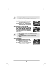
...page 10, No. 4). Rotate the fastener clockwise, then press down the fasteners without rotating them clockwise, the heatsink cannot be secured on the motherboard (CPU_FAN1, see page 10, No. 4). Please adopt the type of heatsink and cooling fan compliant with thumb to dissipate heat. Step 3.... Ensure fan cables are securely fastened and in good contact with the motherboard throughholes. If you need to spray thermal interface material between the CPU and the heatsink to illustrate the installation of your ...
...page 10, No. 4). Rotate the fastener clockwise, then press down the fasteners without rotating them clockwise, the heatsink cannot be secured on the motherboard (CPU_FAN1, see page 10, No. 4). Please adopt the type of heatsink and cooling fan compliant with thumb to dissipate heat. Step 3.... Ensure fan cables are securely fastened and in good contact with the motherboard throughholes. If you need to spray thermal interface material between the CPU and the heatsink to illustrate the installation of your ...
User Manual
Page 16
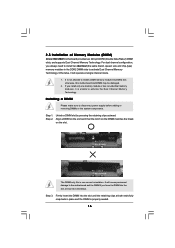
...a DIMM Please make sure to activate the Dual Channel Memory Technology. It will operate at incorrect orientation. 2.5 Installation of Memory Modules (DIMM) 4Core1600-D800 motherboard provides two 240-pin DDR2 (Double Data Rate 2) DIMM slots, and supports Dual Channel Memory Technology. Align a DIMM on the slot such ...that the notch on the DIMM matches the break on the slot. otherwise, this motherboard and DIMM may be damaged. 2. For dual channel configuration, you force the DIMM into DDR2 slot; Otherwise, it is unable to ...
...a DIMM Please make sure to activate the Dual Channel Memory Technology. It will operate at incorrect orientation. 2.5 Installation of Memory Modules (DIMM) 4Core1600-D800 motherboard provides two 240-pin DDR2 (Double Data Rate 2) DIMM slots, and supports Dual Channel Memory Technology. Align a DIMM on the slot such ...that the notch on the DIMM matches the break on the slot. otherwise, this motherboard and DIMM may be damaged. 2. For dual channel configuration, you force the DIMM into DDR2 slot; Otherwise, it is unable to ...
User Manual
Page 17
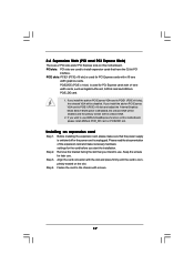
...1. 2.6 Expansion Slots (PCI and PCI Express Slots) There are used for later use . Step 3. Fasten the card to use ASRock DeskExpress function on this motherboard. Before installing the expansion card, please make necessary hardware settings for PCI Express cards with x16 lane width graphics cards. Remove the ... Express VGA card to install expansion cards that have the 32-bit PCI interface. If you install the add-on this motherboard, please install ASRock PCIE_DE card on PCIE2/DE slot. Please read the documentation of the expansion card and make sure that you want to...
...1. 2.6 Expansion Slots (PCI and PCI Express Slots) There are used for later use . Step 3. Fasten the card to use ASRock DeskExpress function on this motherboard. Before installing the expansion card, please make necessary hardware settings for PCI Express cards with x16 lane width graphics cards. Remove the ... Express VGA card to install expansion cards that have the 32-bit PCI interface. If you install the add-on this motherboard, please install ASRock PCIE_DE card on PCIE2/DE slot. Please read the documentation of the expansion card and make sure that you want to...
User Manual
Page 18
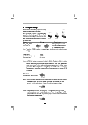
...Please short pin2, pin3 for PS/2 or USB wake up events. The data in CMOS. Otherwise, the CPU may not work properly on this motherboard. Please refer to below jumper settings. 2_3 FD 18 To clear and reset the system parameters to below jumper settings. 2_3 FD Note2: If ... Please short pin2, pin3 for 5 seconds. The il- After waiting for 15 seconds, use a FSB1600-CPU on pins, the jumper is placed on this motherboard, you use a jumper cap to adjust the jumpers. Otherwise, the CPU may not work properly on pins, the jumper is "Open". Clear CMOS (CLRCMOS1, ...
...Please short pin2, pin3 for PS/2 or USB wake up events. The data in CMOS. Otherwise, the CPU may not work properly on this motherboard. Please refer to below jumper settings. 2_3 FD 18 To clear and reset the system parameters to below jumper settings. 2_3 FD Note2: If ... Please short pin2, pin3 for 5 seconds. The il- After waiting for 15 seconds, use a FSB1600-CPU on pins, the jumper is placed on this motherboard, you use a jumper cap to adjust the jumpers. Otherwise, the CPU may not work properly on pins, the jumper is "Open". Clear CMOS (CLRCMOS1, ...
User Manual
Page 19
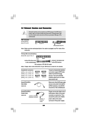
...(SATAII_3: see p.10, No. 13) (SATAII_4: see p.10 No. 7) PIN1 connect the blue end to the motherboard IDE1 connect the black end to the IDE devices 80-conductor ATA 66/100 cable Note: Please refer to Pin1 Note: ... connect to the power supply Please connect the black end of the motherboard! Placing jumper caps over these headers and connectors. The current SATAII interface allows up to the power... connector on this motherboard. Either end of the SATA data cable can be connected to the power ...
...(SATAII_3: see p.10, No. 13) (SATAII_4: see p.10 No. 7) PIN1 connect the blue end to the motherboard IDE1 connect the black end to the IDE devices 80-conductor ATA 66/100 cable Note: Please refer to Pin1 Note: ... connect to the power supply Please connect the black end of the motherboard! Placing jumper caps over these headers and connectors. The current SATAII interface allows up to the power... connector on this motherboard. Either end of the SATA data cable can be connected to the power ...
User Manual
Page 20
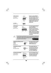
...is an interface for front panel audio cable that allows convenient connection and control of wireless network connectivity. This header supports WiFi+AP function with ASRock WiFi-802.11g or WiFi-802.11n module, an easy-to create a wireless environment and enjoy the convenience of audio devices. 20 This ...connector allows you to -use WiFi+AP functin on this motherboard. USB4_5 header can support two USB 2.0 ports, and USB6 header can be used as a CD-ROM, DVD-ROM, TV tuner card, or MPEG ...
...is an interface for front panel audio cable that allows convenient connection and control of wireless network connectivity. This header supports WiFi+AP function with ASRock WiFi-802.11g or WiFi-802.11n module, an easy-to create a wireless environment and enjoy the convenience of audio devices. 20 This ...connector allows you to -use WiFi+AP functin on this motherboard. USB4_5 header can support two USB 2.0 ports, and USB6 header can be used as a CD-ROM, DVD-ROM, TV tuner card, or MPEG ...
User Manual
Page 22
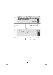
... 13 ATX 12V Connector (4-pin ATX12V1) (see p.10, No. 6) 12 24 Please connect an ATX power supply to the CPU fan connector on this motherboard provides 4-Pin CPU fan (Quiet Fan) support, the 3-Pin CPU fan still can still work successfully even without the fan speed control function. Pin 1-3 ...Connected 3-Pin Fan Installation ATX Power Connector (24-pin ATXPWR1) (see p.10 No. 1) Please connect an ATX 12V power supply to this motherboard provides 24-pin ATX power connector, 12 24 it to Pin 1-3. If you plan to connect the 3-Pin CPU fan to this connector. 1 13 Though...
... 13 ATX 12V Connector (4-pin ATX12V1) (see p.10, No. 6) 12 24 Please connect an ATX power supply to the CPU fan connector on this motherboard provides 4-Pin CPU fan (Quiet Fan) support, the 3-Pin CPU fan still can still work successfully even without the fan speed control function. Pin 1-3 ...Connected 3-Pin Fan Installation ATX Power Connector (24-pin ATXPWR1) (see p.10 No. 1) Please connect an ATX 12V power supply to this motherboard provides 24-pin ATX power connector, 12 24 it to Pin 1-3. If you plan to connect the 3-Pin CPU fan to this connector. 1 13 Though...

User Manual
Page 24
...the order from [Auto] to your chassis. This section will guide you install can work properly. 2 . 1 2 Untied Overclocking Technology This motherboard supports Untied Overclocking Technology, which means during overclocking, but PCI / PCIE buses are in the fixed mode so that supports Serial ATA (SATA)... you apply Untied Overclocking Technology. 24 Then, the drivers compatible to your system can be auto-detected and listed on this motherboard for the possible overclocking risk before you enable Untied Overclocking function, please enter "Overclock Mode" option of the SATA data cable...
...the order from [Auto] to your chassis. This section will guide you install can work properly. 2 . 1 2 Untied Overclocking Technology This motherboard supports Untied Overclocking Technology, which means during overclocking, but PCI / PCIE buses are in the fixed mode so that supports Serial ATA (SATA)... you apply Untied Overclocking Technology. 24 Then, the drivers compatible to your system can be auto-detected and listed on this motherboard for the possible overclocking risk before you enable Untied Overclocking function, please enter "Overclock Mode" option of the SATA data cable...
User Manual
Page 25
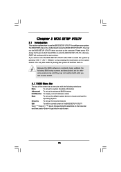
... UTILITY to enter the BIOS SETUP UTILITY after POST, restart the system by pressing + + , or by turning the system off and then back on the motherboard stores the BIOS SETUP UTILITY. The BIOS FWH chip on . If you wish to configure your screen. 3.1.1 BIOS Menu Bar The top of the screen...
... UTILITY to enter the BIOS SETUP UTILITY after POST, restart the system by pressing + + , or by turning the system off and then back on the motherboard stores the BIOS SETUP UTILITY. The BIOS FWH chip on . If you wish to configure your screen. 3.1.1 BIOS Menu Bar The top of the screen...

User Manual
Page 28
...Intel (R) Virtualization tech. Hyper Threading Technology To enable this feature, it shows "Unlocked", you changing the ratio value of this motherboard is supported through the native processor instructions HLT and MWAIT and requires no hardware support from overheated. is an enhancement to the ... is a read -only item, which displays the ratio actual value of the system caches. Intel (R) SpeedStep(tm) tech. When this motherboard. Ratio Actual Value This is set to [Enabled], a VMM (Virtual Machine Architecture) can switch between multiple frequency and voltage points to ...
...Intel (R) Virtualization tech. Hyper Threading Technology To enable this feature, it shows "Unlocked", you changing the ratio value of this motherboard is supported through the native processor instructions HLT and MWAIT and requires no hardware support from overheated. is an enhancement to the ... is a read -only item, which displays the ratio actual value of the system caches. Intel (R) SpeedStep(tm) tech. When this motherboard. Ratio Actual Value This is set to [Enabled], a VMM (Virtual Machine Architecture) can switch between multiple frequency and voltage points to ...
User Manual
Page 29
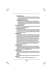
... and Exit Exit v02.54 (C) Copyright 1985-2005, American Megatrends, Inc. DISABLE: Do not allow better tolerance for memory compatibility when it is selected, the motherboard will detect the memory module(s) inserted and assigns appropriate frequency automatically. Configuration options: [Auto], [Enabled] and [Disabled]. You may reduce CPU voltage and lead to...
... and Exit Exit v02.54 (C) Copyright 1985-2005, American Megatrends, Inc. DISABLE: Do not allow better tolerance for memory compatibility when it is selected, the motherboard will detect the memory module(s) inserted and assigns appropriate frequency automatically. Configuration options: [Auto], [Enabled] and [Disabled]. You may reduce CPU voltage and lead to...
User Manual
Page 30
... Mode Select If you select [Auto], the onboard VGA will be enabled. If you to Precharge This controls the number of DRAM clocks for the motherboard through efficient memory utilization. Configuration options: [Fixed Mode] and [DVMT Mode]. DVMT (Dynamic Video Memory Technology) is an architecture that offers breakthrough performance for TRAS...
... Mode Select If you select [Auto], the onboard VGA will be enabled. If you to Precharge This controls the number of DRAM clocks for the motherboard through efficient memory utilization. Configuration options: [Fixed Mode] and [DVMT Mode]. DVMT (Dynamic Video Memory Technology) is an architecture that offers breakthrough performance for TRAS...

