Installation Guide
Page 7
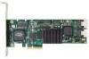
... the supplied interface cables. System Requirements Table 1: Required Slots for 3ware RAID Controller Models Controller Model 9650SE-2LP 9650SE-4LPML 9650SE-8LPML 9650SE-12LPML 9650SE-16LPML 9650SE-24M8 PCI-E X1 Yes No No No No No PCI-E X4 Yes Yes Yes No No No PCI-E X8 Yes Yes Yes Yes Yes Yes PCI-E x16 Yes Yes Yes Yes Yes Yes Drive Requirements Depending...
... the supplied interface cables. System Requirements Table 1: Required Slots for 3ware RAID Controller Models Controller Model 9650SE-2LP 9650SE-4LPML 9650SE-8LPML 9650SE-12LPML 9650SE-16LPML 9650SE-24M8 PCI-E X1 Yes No No No No No PCI-E X4 Yes Yes Yes No No No PCI-E X8 Yes Yes Yes Yes Yes Yes PCI-E x16 Yes Yes Yes Yes Yes Yes Drive Requirements Depending...
Installation Guide
Page 9
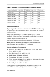
9650SE RAID Controller Card Models Figure 2. 4-Port 3ware 9650SE-4LPML Serial ATA RAID Controller I2C connector LED Connector Heat Sink Ports: 0 thru 3 Slots for battery holder BBU connector and hole for post Figure 3. 8-Port 3ware 9650SE-8LPML Serial ATA RAID Controller I2C connector LED Connectors Heat Sink Ports: 4 thru 7 0 thru 3 Slots for battery BBU connector and hole for post www.3ware.com 5
9650SE RAID Controller Card Models Figure 2. 4-Port 3ware 9650SE-4LPML Serial ATA RAID Controller I2C connector LED Connector Heat Sink Ports: 0 thru 3 Slots for battery holder BBU connector and hole for post Figure 3. 8-Port 3ware 9650SE-8LPML Serial ATA RAID Controller I2C connector LED Connectors Heat Sink Ports: 4 thru 7 0 thru 3 Slots for battery BBU connector and hole for post www.3ware.com 5
Installation Guide
Page 21
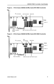
...correctly, you will feel it click into place. Figure 12. Connect the Cables to the Controller The 9650SE-4LPML, 9650SE-8LPML, 9650SE-12ML, 9650SE16ML, and 9650SE-24M8 models are all multi-lane controllers. (For the 9650SE-2LP, turn to the previous page.) 1 Take out the multi-lane cables provided with an SFF-... the Cables to a multi-lane connector on the which model of the 9650SE you have, and the number of drives you will be connecting, you will connect between one and four multi-lane cables. www.3ware.com 17 Connecting a Multi-lane Cable with your controller. 2 Connect each...
...correctly, you will feel it click into place. Figure 12. Connect the Cables to the Controller The 9650SE-4LPML, 9650SE-8LPML, 9650SE-12ML, 9650SE16ML, and 9650SE-24M8 models are all multi-lane controllers. (For the 9650SE-2LP, turn to the previous page.) 1 Take out the multi-lane cables provided with an SFF-... the Cables to a multi-lane connector on the which model of the 9650SE you have, and the number of drives you will be connecting, you will connect between one and four multi-lane cables. www.3ware.com 17 Connecting a Multi-lane Cable with your controller. 2 Connect each...
Installation Guide
Page 26
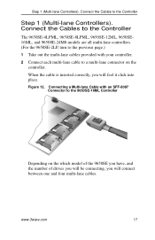
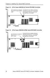
... LED indicators for individual drives on J7: 0 and 1 (left to right) Overall LED drive status indicator: the last two pins of J7. Figure 16. 4-Port 3ware 9650SE-4LPML Serial ATA RAID Controller LED indicators for individual drives on J7: 0, 1, 2, 3 (left to right) Overall LED drive status indicator: the last two pins of J7... the two pins and the cathode is the upper. The anode is the lower of the two pins and the cathode is the upper. 22 3ware 9650SE Serial ATA RAID Controller Installation Guide
... LED indicators for individual drives on J7: 0 and 1 (left to right) Overall LED drive status indicator: the last two pins of J7. Figure 16. 4-Port 3ware 9650SE-4LPML Serial ATA RAID Controller LED indicators for individual drives on J7: 0, 1, 2, 3 (left to right) Overall LED drive status indicator: the last two pins of J7... the two pins and the cathode is the upper. The anode is the lower of the two pins and the cathode is the upper. 22 3ware 9650SE Serial ATA RAID Controller Installation Guide
Installation Guide
Page 30
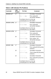
Installing Your 3ware RAID Controller Table 2: LED Indicator Pin Positions Controller LED Header Pin Pair Comment 9650SE-2LP J7 9650SE-4LPML J7 9650SE-8LPML J7 J8 9650SE-12ML J7 J8 J9 : : : : : Orientation Horizontal 0 1 : : All Port number/All (all activity indicator) k-cathode-minus is on the top a-anode-plus is on the bottom : : : : : ... indicator) : : : : : Orientation Horizontal 8 9 10 11 All Port number/All (all activity indicator) k-cathode-minus is on the top a-anode-plus is on the bottom 26 3ware 9650SE Serial ATA RAID Controller Installation Guide Chapter 2.
Installing Your 3ware RAID Controller Table 2: LED Indicator Pin Positions Controller LED Header Pin Pair Comment 9650SE-2LP J7 9650SE-4LPML J7 9650SE-8LPML J7 J8 9650SE-12ML J7 J8 J9 : : : : : Orientation Horizontal 0 1 : : All Port number/All (all activity indicator) k-cathode-minus is on the top a-anode-plus is on the bottom : : : : : ... indicator) : : : : : Orientation Horizontal 8 9 10 11 All Port number/All (all activity indicator) k-cathode-minus is on the top a-anode-plus is on the bottom 26 3ware 9650SE Serial ATA RAID Controller Installation Guide Chapter 2.