Installation Guide
Page 3
Installing Your 3ware RAID Controller 15 Tools You Need 15 Before You Start 15 Step 1 (9650SE-2LP). Connect the Cables to the SATA/SAS Drive Multi-Lane Backplane . 21 Step 4. Connect Cables to the Controller . . . 17 Step 2. Installing the ...lane Controllers). Connecting Drive Activity LED Indicators (Optional 21 Step 5. Finishing Up the RAID Controller Installation 28 Step 6. Table of this Package 1 System Requirements 2 9650SE RAID Controller Card Models 4 Cables 7 Safety Information 10 Chapter 2. Getting Started 1 Contents of Contents About this manual 40 www...
Installing Your 3ware RAID Controller 15 Tools You Need 15 Before You Start 15 Step 1 (9650SE-2LP). Connect the Cables to the SATA/SAS Drive Multi-Lane Backplane . 21 Step 4. Connect Cables to the Controller . . . 17 Step 2. Installing the ...lane Controllers). Connecting Drive Activity LED Indicators (Optional 21 Step 5. Finishing Up the RAID Controller Installation 28 Step 6. Table of this Package 1 System Requirements 2 9650SE RAID Controller Card Models 4 Cables 7 Safety Information 10 Chapter 2. Getting Started 1 Contents of Contents About this manual 40 www...
Installation Guide
Page 5
... be purchased separately, and is not supported on 9650SE-2LP.) „ RAID levels 0, 1, 5, 6, 10, 50, Single Disk, JBOD, and Hot Spare (RAID 6 and RAID 50 are available only with 3ware RAID controller models that have 8 or more ports) „ PCI Express® x1, x4, or x8 connectivity ...Contents of this Package If you purchased a full retail kit, the following items are included: „ This document, 3ware 9650SE Serial ATA RAID Controller Installation Guide „ 3ware CD-ROM with driver, software, and additional...
... be purchased separately, and is not supported on 9650SE-2LP.) „ RAID levels 0, 1, 5, 6, 10, 50, Single Disk, JBOD, and Hot Spare (RAID 6 and RAID 50 are available only with 3ware RAID controller models that have 8 or more ports) „ PCI Express® x1, x4, or x8 connectivity ...Contents of this Package If you purchased a full retail kit, the following items are included: „ This document, 3ware 9650SE Serial ATA RAID Controller Installation Guide „ 3ware CD-ROM with driver, software, and additional...
Installation Guide
Page 7
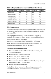
.../s) or SATA-2 (3.0 Gb/s) standards. System Requirements Table 1: Required Slots for 3ware RAID Controller Models Controller Model 9650SE-2LP 9650SE-4LPML 9650SE-8LPML 9650SE-12LPML 9650SE-16LPML 9650SE-24M8 PCI-E X1 Yes No No No No No PCI-E X4 Yes Yes Yes No No No PCI-E X8 Yes Yes Yes Yes Yes Yes PCI-E x16 Yes Yes Yes Yes Yes Yes Drive Requirements Depending...
.../s) or SATA-2 (3.0 Gb/s) standards. System Requirements Table 1: Required Slots for 3ware RAID Controller Models Controller Model 9650SE-2LP 9650SE-4LPML 9650SE-8LPML 9650SE-12LPML 9650SE-16LPML 9650SE-24M8 PCI-E X1 Yes No No No No No PCI-E X4 Yes Yes Yes No No No PCI-E X8 Yes Yes Yes Yes Yes Yes PCI-E x16 Yes Yes Yes Yes Yes Yes Drive Requirements Depending...
Installation Guide
Page 8
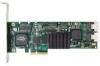
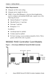
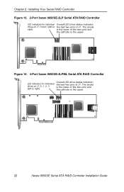
Getting Started Other Requirements „ Adequate air flow and cooling „ Adequate power supply for drives „ 3DM 2 (3ware Disk Manager), a browser-based application used to configure and maintain RAID units, requires one of the following browsers: „ Internet Explorer 5.5 and later „... „ Cookies must be enabled „ For best viewing, screen resolution should be 1024 x 768 or greater, with 16-bit color or greater. 9650SE RAID Controller Card Models Figure 1. 2-Port 3ware 9650SE-2LP Serial ATA RAID Controller LED Connector Heat Sink Ports: 0 (on top) 1 (on the bottom...
Getting Started Other Requirements „ Adequate air flow and cooling „ Adequate power supply for drives „ 3DM 2 (3ware Disk Manager), a browser-based application used to configure and maintain RAID units, requires one of the following browsers: „ Internet Explorer 5.5 and later „... „ Cookies must be enabled „ For best viewing, screen resolution should be 1024 x 768 or greater, with 16-bit color or greater. 9650SE RAID Controller Card Models Figure 1. 2-Port 3ware 9650SE-2LP Serial ATA RAID Controller LED Connector Heat Sink Ports: 0 (on top) 1 (on the bottom...
Installation Guide
Page 20
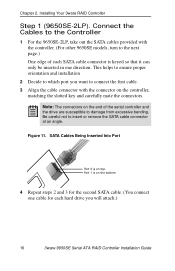
...first cable. 3 Align the cable connector with the controller. (For other 9650SE models, turn to the Controller 1 For the 9650SE-2LP, take out the SATA cables provided with the connector on top. Installing Your 3ware RAID Controller Step 1 (9650SE-2LP). Connect the Cables to the next page.) One edge of each SATA cable...cable. (You connect one direction. Chapter 2. This helps to ensure proper orientation and installation 2 Decide to which port you will attach.) 16 3ware 9650SE Serial ATA RAID Controller Installation Guide Figure 11. Be careful not to damage from excessive bending.
...first cable. 3 Align the cable connector with the controller. (For other 9650SE models, turn to the Controller 1 For the 9650SE-2LP, take out the SATA cables provided with the connector on top. Installing Your 3ware RAID Controller Step 1 (9650SE-2LP). Connect the Cables to the next page.) One edge of each SATA cable...cable. (You connect one direction. Chapter 2. This helps to ensure proper orientation and installation 2 Decide to which port you will attach.) 16 3ware 9650SE Serial ATA RAID Controller Installation Guide Figure 11. Be careful not to damage from excessive bending.
Installation Guide
Page 21
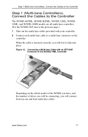
... will connect between one and four multi-lane cables. Connect the Cables to the Controller The 9650SE-4LPML, 9650SE-8LPML, 9650SE-12ML, 9650SE16ML, and 9650SE-24M8 models are all multi-lane controllers. (For the 9650SE-2LP, turn to the previous page.) 1 Take out the multi-lane cables provided with an SFF...-8087 Connector to the 9650SE-16ML Controller Depending on the controller. When the cable is inserted correctly, you will feel it click into place. www.3ware.com 17 Figure 12...
... will connect between one and four multi-lane cables. Connect the Cables to the Controller The 9650SE-4LPML, 9650SE-8LPML, 9650SE-12ML, 9650SE16ML, and 9650SE-24M8 models are all multi-lane controllers. (For the 9650SE-2LP, turn to the previous page.) 1 Take out the multi-lane cables provided with an SFF...-8087 Connector to the 9650SE-16ML Controller Depending on the controller. When the cable is inserted correctly, you will feel it click into place. www.3ware.com 17 Figure 12...
Installation Guide
Page 22
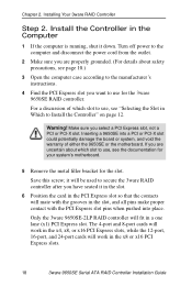
..., see the documentation for your system's motherboard. 5 Remove the metal filler bracket for the 3ware 9650SE RAID controller. Install the Controller in a one lane (x1) PCI Express slot. it down. Save this screw; Inserting a 9650SE into place. Warning! Only the 3ware 9650SE-2LP RAID controller will fit in the Computer 1 If the computer is running, shut it...
..., see the documentation for your system's motherboard. 5 Remove the metal filler bracket for the 3ware 9650SE RAID controller. Install the Controller in a one lane (x1) PCI Express slot. it down. Save this screw; Inserting a 9650SE into place. Warning! Only the 3ware 9650SE-2LP RAID controller will fit in the Computer 1 If the computer is running, shut it...
Installation Guide
Page 26
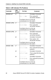
The anode is the lower of the two pins and the cathode is the upper. Figure 16. 4-Port 3ware 9650SE-4LPML Serial ATA RAID Controller LED indicators for individual drives on J7: 0, 1, 2, 3 (left to right) Overall LED drive status indicator: the last ...of J7. The anode is the lower of the two pins and the cathode is the upper. 22 3ware 9650SE Serial ATA RAID Controller Installation Guide Chapter 2. Installing Your 3ware RAID Controller Figure 15. 2-Port 3ware 9650SE-2LP Serial ATA RAID Controller LED indicators for individual drives on J7: 0 and 1 (left to right) Overall...
The anode is the lower of the two pins and the cathode is the upper. Figure 16. 4-Port 3ware 9650SE-4LPML Serial ATA RAID Controller LED indicators for individual drives on J7: 0, 1, 2, 3 (left to right) Overall LED drive status indicator: the last ...of J7. The anode is the lower of the two pins and the cathode is the upper. 22 3ware 9650SE Serial ATA RAID Controller Installation Guide Chapter 2. Installing Your 3ware RAID Controller Figure 15. 2-Port 3ware 9650SE-2LP Serial ATA RAID Controller LED indicators for individual drives on J7: 0 and 1 (left to right) Overall...
Installation Guide
Page 30
Chapter 2. Installing Your 3ware RAID Controller Table 2: LED Indicator Pin Positions Controller LED Header Pin Pair Comment 9650SE-2LP J7 9650SE-4LPML J7 9650SE-8LPML J7 J8 9650SE-12ML J7 J8 J9 : : : : : Orientation Horizontal 0 1 : : All Port number/All (all activity indicator) k-cathode-minus is on the top a-anode-plus is on the bottom : : : : : ... indicator) : : : : : Orientation Horizontal 8 9 10 11 All Port number/All (all activity indicator) k-cathode-minus is on the top a-anode-plus is on the bottom 26 3ware 9650SE Serial ATA RAID Controller Installation Guide
Chapter 2. Installing Your 3ware RAID Controller Table 2: LED Indicator Pin Positions Controller LED Header Pin Pair Comment 9650SE-2LP J7 9650SE-4LPML J7 9650SE-8LPML J7 J8 9650SE-12ML J7 J8 J9 : : : : : Orientation Horizontal 0 1 : : All Port number/All (all activity indicator) k-cathode-minus is on the top a-anode-plus is on the bottom : : : : : ... indicator) : : : : : Orientation Horizontal 8 9 10 11 All Port number/All (all activity indicator) k-cathode-minus is on the top a-anode-plus is on the bottom 26 3ware 9650SE Serial ATA RAID Controller Installation Guide
Installation Guide
Page 33
... disks. The 9650SE-2LP does not support the BBU. Important: The battery is flushed to data loss in the system, such as video cards. If possible, place the controller with the BBU in a slot with good airflow, away from components that can be attached to a 3ware 9650SE RAID controller to... supply power to 72 hours). Caution: Both the 3ware RAID controller and the BBU are grounded. Use a grounding strap, or work on an ESD-protective mat. „...
... disks. The 9650SE-2LP does not support the BBU. Important: The battery is flushed to data loss in the system, such as video cards. If possible, place the controller with the BBU in a slot with good airflow, away from components that can be attached to a 3ware 9650SE RAID controller to... supply power to 72 hours). Caution: Both the 3ware RAID controller and the BBU are grounded. Use a grounding strap, or work on an ESD-protective mat. „...