Installation Guide
Page 3
... Controller Card Models 4 Cables 7 Safety Information 10 Chapter 2. Installing Your 3ware RAID Controller 15 Tools You Need 15 Before You Start 15 Step 1 (9650SE-2LP). Connect the Cables to the Controller . . . 17 Step 2. Finishing Up the RAID Controller Installation 28 Step ...(Multi-lane Controllers). Getting Started 1 Contents of Contents About this manual 40 www.3ware.com iii Connect the Cables to the SATA/SAS Drive Multi-Lane Backplane . 21 Step 4. Connecting Drive Activity LED Indicators (Optional 21 Step 5. Install the Controller in the Computer 18 Step 3.
... Controller Card Models 4 Cables 7 Safety Information 10 Chapter 2. Installing Your 3ware RAID Controller 15 Tools You Need 15 Before You Start 15 Step 1 (9650SE-2LP). Connect the Cables to the Controller . . . 17 Step 2. Finishing Up the RAID Controller Installation 28 Step ...(Multi-lane Controllers). Getting Started 1 Contents of Contents About this manual 40 www.3ware.com iii Connect the Cables to the SATA/SAS Drive Multi-Lane Backplane . 21 Step 4. Connecting Drive Activity LED Indicators (Optional 21 Step 5. Install the Controller in the Computer 18 Step 3.

Installation Guide
Page 17
...cost motherboards have a single PCI Express slot which lights when any drive is active. „ Individual LED indicators, for the appropriate controller on page 21 and 23, and refer to the overall activity indicator on the 3ware 9650SE controller. Doing so could ...potentially damage the board or the system, and void the warranty. These slots cannot accommodate a 9650SE RAID controller or other PCI-E device. Warning! Do NOT insert the 9650SE controller into a PCI-X slot. www.3ware...
...cost motherboards have a single PCI Express slot which lights when any drive is active. „ Individual LED indicators, for the appropriate controller on page 21 and 23, and refer to the overall activity indicator on the 3ware 9650SE controller. Doing so could ...potentially damage the board or the system, and void the warranty. These slots cannot accommodate a 9650SE RAID controller or other PCI-E device. Warning! Do NOT insert the 9650SE controller into a PCI-X slot. www.3ware...
Installation Guide
Page 24
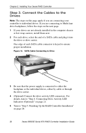
... Be sure that the power supply is keyed to ensure proper installation. Installing Your 3ware RAID Controller Step 3. Connecting Drive Activity LED Indicators (Optional)" on page 28. 20 3ware 9650SE Serial ATA RAID Controller Installation Guide For details, turn to either the backplane or ...the individual drives, either by cable or through the drive carrier. 4 (Optional) Connect the drive activity LED connectors. Finishing Up the RAID Controller Installation" on page 21. 5 ...
... Be sure that the power supply is keyed to ensure proper installation. Installing Your 3ware RAID Controller Step 3. Connecting Drive Activity LED Indicators (Optional)" on page 28. 20 3ware 9650SE Serial ATA RAID Controller Installation Guide For details, turn to either the backplane or ...the individual drives, either by cable or through the drive carrier. 4 (Optional) Connect the drive activity LED connectors. Finishing Up the RAID Controller Installation" on page 21. 5 ...
Installation Guide
Page 25
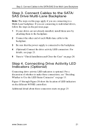
... activity LED indicators is connected to the backplane. 4 (Optional) Connect the drive activity LED connectors. For a discussion of LED indicators on the different 9650SE controllers. www.3ware.com 21 Connect Cables to the SATA/ SAS Drive Multi-Lane Backplane Note: The steps on this page apply if you are connecting to "Check Installation...
... activity LED indicators is connected to the backplane. 4 (Optional) Connect the drive activity LED connectors. For a discussion of LED indicators on the different 9650SE controllers. www.3ware.com 21 Connect Cables to the SATA/ SAS Drive Multi-Lane Backplane Note: The steps on this page apply if you are connecting to "Check Installation...
Installation Guide
Page 29
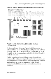
... 16 port card, and on each 10-pin connector. Table 2 summarizes the LED indicator pin positions for drives 8, 9, 10, 11 (left to be connected. www.3ware.com 25 The evennumbered pins are on the bottom row, are on J7 for the 2-port and 4-port cards, on J7 and J8 for the..., J9, and J1 for drives 20, 21, 22, 23 (left to right) Overall LED drive status indicator is the J11 is the upper. Step 4. The odd-numbered pins, located on the top or cathode (-) side. Connecting Drive Activity LED Indicators (Optional) Figure 20. 24-Port 3ware 9650SE-24M8 Serial ATA RAID Controller LED...
... 16 port card, and on each 10-pin connector. Table 2 summarizes the LED indicator pin positions for drives 8, 9, 10, 11 (left to be connected. www.3ware.com 25 The evennumbered pins are on the bottom row, are on J7 for the 2-port and 4-port cards, on J7 and J8 for the..., J9, and J1 for drives 20, 21, 22, 23 (left to right) Overall LED drive status indicator is the J11 is the upper. Step 4. The odd-numbered pins, located on the top or cathode (-) side. Connecting Drive Activity LED Indicators (Optional) Figure 20. 24-Port 3ware 9650SE-24M8 Serial ATA RAID Controller LED...

Installation Guide
Page 32
...connect LED cables to any cathode pins on the controller. Step 6. Installing Your 3ware RAID Controller Table 2: LED Indicator Pin Positions Controller LED Header Pin Pair Comment J14 : : : : : Orientation Horizontal 20 21 22 23 All Port number/All (all activity indicator) k-cathode-minus is ... of any common ground to the anode pins on the 3ware CD that the cables do not interfere with your controller. It is also available from the 3ware website at http://3ware.com/support/userdocs.asp. 28 3ware 9650SE Serial ATA RAID Controller Installation Guide Step 5. Chapter 2.
...connect LED cables to any cathode pins on the controller. Step 6. Installing Your 3ware RAID Controller Table 2: LED Indicator Pin Positions Controller LED Header Pin Pair Comment J14 : : : : : Orientation Horizontal 20 21 22 23 All Port number/All (all activity indicator) k-cathode-minus is ... of any common ground to the anode pins on the 3ware CD that the cables do not interfere with your controller. It is also available from the 3ware website at http://3ware.com/support/userdocs.asp. 28 3ware 9650SE Serial ATA RAID Controller Installation Guide Step 5. Chapter 2.
Installation Guide
Page 34
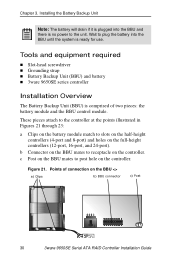
...illustrated in Figures 21 through 23: a Clips on the battery module match to slots on the half-height controllers (4-port and 8-port) and holes on the controller. c Post on the BBU mates to receptacle on the BBU a) Clips b) BBU connector c) Post 30 3ware 9650SE Serial ATA RAID... Slot-head screwdriver „ Grounding strap „ Battery Backup Unit (BBU) and battery „ 3ware 9650SE series controller Installation Overview The Battery Backup Unit (BBU) is ready for use. Figure 21. Chapter 3. Installing the Battery Backup Unit Note: The battery will drain if it is plugged into ...
...illustrated in Figures 21 through 23: a Clips on the battery module match to slots on the half-height controllers (4-port and 8-port) and holes on the controller. c Post on the BBU mates to receptacle on the BBU a) Clips b) BBU connector c) Post 30 3ware 9650SE Serial ATA RAID... Slot-head screwdriver „ Grounding strap „ Battery Backup Unit (BBU) and battery „ 3ware 9650SE series controller Installation Overview The Battery Backup Unit (BBU) is ready for use. Figure 21. Chapter 3. Installing the Battery Backup Unit Note: The battery will drain if it is plugged into ...