Installation Guide
Page 1
Installation Guide NJ100 Network Jack 3CNJ100 4-port 10/100 Mbps Unmanaged Ethernet Switch http://www.3com.com/ http://www.3com.com/productreg 09-2141-000 Published September 2001
Installation Guide NJ100 Network Jack 3CNJ100 4-port 10/100 Mbps Unmanaged Ethernet Switch http://www.3com.com/ http://www.3com.com/productreg 09-2141-000 Published September 2001
Installation Guide
Page 3
... Ethernet Power Supply 12 Using the 3Com Local Power Supply 12 Setting the Power Over Ethernet Dip Switches 13 Installing the Adapter Plate and Pass-Through Ports 15 Planning the Installation 17 Setting up the Network Cabling at Your Site 19 Connecting the Network Jack to the Network 19 Mounting the Network Jack 22 Connecting the Local Power...
... Ethernet Power Supply 12 Using the 3Com Local Power Supply 12 Setting the Power Over Ethernet Dip Switches 13 Installing the Adapter Plate and Pass-Through Ports 15 Planning the Installation 17 Setting up the Network Cabling at Your Site 19 Connecting the Network Jack to the Network 19 Mounting the Network Jack 22 Connecting the Local Power...
Installation Guide
Page 5
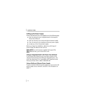
... of the following ways: I Over the network via an optional local power supply. See "Using the 3Com Local Power Supply" on an Ethernet network by allowing up to two additional devices to be connected to receive both data and power from the same network cable. The Network Jack brings switching capabilities to any standard electrical wall outlet...
... of the following ways: I Over the network via an optional local power supply. See "Using the 3Com Local Power Supply" on an Ethernet network by allowing up to two additional devices to be connected to receive both data and power from the same network cable. The Network Jack brings switching capabilities to any standard electrical wall outlet...

Installation Guide
Page 6
Installation Guide About the Network Jack The following diagram shows the front view of the Network Jack. 2 3 1 2 1 3 4 4 5 2
Installation Guide About the Network Jack The following diagram shows the front view of the Network Jack. 2 3 1 2 1 3 4 4 5 2
Installation Guide
Page 7
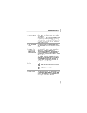
... 15 for more information. 4 LEDs Indicates network connection status. it can be used to power the Network Jack with a local power supply (available for purchase from 3Com); Indicates power status. 5 Power socket Can be connected to the network. required if your network does not support Power Over Ethernet. 3 About the Network Jack 1 Switched ports Allow up to four devices...
... 15 for more information. 4 LEDs Indicates network connection status. it can be used to power the Network Jack with a local power supply (available for purchase from 3Com); Indicates power status. 5 Power socket Can be connected to the network. required if your network does not support Power Over Ethernet. 3 About the Network Jack 1 Switched ports Allow up to four devices...
Installation Guide
Page 9
See "Setting the Power Over Ethernet Dip Switches" on the network switch to which the Network Jack is connected is required only if your network supports Power Over Ethernet, or if you are using a multi-port Ethernet power supply. port Make ... port connector Connects the installed pass-through port to the network. Setting the dip switches is configured as a standard MDI-X port. 2 Slot for instructions. 5 About the Network Jack 1 Ethernet uplink Connects the Network Jack to the network. 4 Dip switches Determine the type of Power Over Ethernet (Capacitive Power Discovery...
See "Setting the Power Over Ethernet Dip Switches" on the network switch to which the Network Jack is connected is required only if your network supports Power Over Ethernet, or if you are using a multi-port Ethernet power supply. port Make ... port connector Connects the installed pass-through port to the network. Setting the dip switches is configured as a standard MDI-X port. 2 Slot for instructions. 5 About the Network Jack 1 Ethernet uplink Connects the Network Jack to the network. 4 Dip switches Determine the type of Power Over Ethernet (Capacitive Power Discovery...
Installation Guide
Page 10
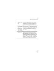
..., the following items, which are shipped with the single pack: I Adapter plates for installing connectors to the Network Jack (required only if your product at: www.3com.com/productreg. The adapter plates accommodate connectors from the manufacturer. I Avaya (RJ-45 and RJ-11) NOTE... items are included with a female RJ-45 connector). I Adapter plate screws (2) for mounting the adapter plate to www.3com.com/. The Network Jack is terminated with the Network Jack: I 6x32 screws (2 per package). For a list of fice cubicle. and 20-packs. Installation Guide Before ...
..., the following items, which are shipped with the single pack: I Adapter plates for installing connectors to the Network Jack (required only if your product at: www.3com.com/productreg. The adapter plates accommodate connectors from the manufacturer. I Avaya (RJ-45 and RJ-11) NOTE... items are included with a female RJ-45 connector). I Adapter plate screws (2) for mounting the adapter plate to www.3com.com/. The Network Jack is terminated with the Network Jack: I 6x32 screws (2 per package). For a list of fice cubicle. and 20-packs. Installation Guide Before ...

Installation Guide
Page 11
...Network Jack works with the following optional components, all of fewer than 1.5 inches. Multi-port Ethernet power supply For providing Power Over Ethernet to power up to a cubicle; required if the cubicle opening: I Has a depth of which are available from 3Com. Order online at www.3com... For installing pass-through port 3CNJAP-PA-20 connectors of your network does not support Power Over Ethernet. 3CNJPSL 7 required if your choice that the Network Jack is properly mounted to 24 Network Jacks. 3CNJPSE24 3C10220 3C10222 Local power supply For locally powering a single...
...Network Jack works with the following optional components, all of fewer than 1.5 inches. Multi-port Ethernet power supply For providing Power Over Ethernet to power up to a cubicle; required if the cubicle opening: I Has a depth of which are available from 3Com. Order online at www.3com... For installing pass-through port 3CNJAP-PA-20 connectors of your network does not support Power Over Ethernet. 3CNJPSL 7 required if your choice that the Network Jack is properly mounted to 24 Network Jacks. 3CNJPSE24 3C10220 3C10222 Local power supply For locally powering a single...
Installation Guide
Page 12
... the 3Com network that uses Capacitive Power web site Discovery Process-compatible Power Over Ethernet. optional). 4 Plan the installation (page 17). 5 Set up the power supply (page 10). 2 Set the Power Over Ethernet dip switches (page 13; optional, required only if your site (page 19). 6 Connect the Network Jack to the network (page 19). 7 Mount the Network Jack...
... the 3Com network that uses Capacitive Power web site Discovery Process-compatible Power Over Ethernet. optional). 4 Plan the installation (page 17). 5 Set up the power supply (page 10). 2 Set the Power Over Ethernet dip switches (page 13; optional, required only if your site (page 19). 6 Connect the Network Jack to the network (page 19). 7 Mount the Network Jack...

Installation Guide
Page 13
... RJ-45 4 coupler cable 9 optional) not required if your network supports Power Over Ethernet or if you are included in the sections that is being connected to the Network Jack (page 23). Installing the Network Jack 8 Connect the local power supply (page 23; Detailed installation instructions... are using a single-port or multi-port power supply). 9 Connect network devices to an Ethernet network cable that follow. The ...
... RJ-45 4 coupler cable 9 optional) not required if your network supports Power Over Ethernet or if you are included in the sections that is being connected to the Network Jack (page 23). Installing the Network Jack 8 Connect the local power supply (page 23; Detailed installation instructions... are using a single-port or multi-port power supply). 9 Connect network devices to an Ethernet network cable that follow. The ...
Installation Guide
Page 14
...use Power Over Ethernet, you must have a switch on page 11. 10 You must then determine if it . I Over the network via a 3Com local power supply. Before you begin the installation, determine which type of power supply the Network Jack will use a multi-port Ethernet power supply,... you must connect the power supply to www.3com.com/. Using an Integrated Switch with Capacitive Power Discovery ...
...use Power Over Ethernet, you must have a switch on page 11. 10 You must then determine if it . I Over the network via a 3Com local power supply. Before you begin the installation, determine which type of power supply the Network Jack will use a multi-port Ethernet power supply,... you must connect the power supply to www.3com.com/. Using an Integrated Switch with Capacitive Power Discovery ...

Installation Guide
Page 15
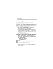
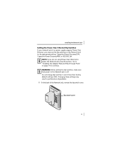
See "Obtaining Optional Components" on page 7 for ordering information. For complete installation instructions, see the multi-port Ethernet power supply documentation. Network switch Wiring closet To network hub/switch To Network Jack Multi-port Ethernet 1 2 power supply 3 4 11 Installing the Network Jack The multi-port Ethernet power supply from 3Com connects to an existing Ethernet or Fast Ethernet infrastructure with standard Category 5 or Category 5e UTP cabling, and powers up to 24 Network Jacks.
See "Obtaining Optional Components" on page 7 for ordering information. For complete installation instructions, see the multi-port Ethernet power supply documentation. Network switch Wiring closet To network hub/switch To Network Jack Multi-port Ethernet 1 2 power supply 3 4 11 Installing the Network Jack The multi-port Ethernet power supply from 3Com connects to an existing Ethernet or Fast Ethernet infrastructure with standard Category 5 or Category 5e UTP cabling, and powers up to 24 Network Jacks.

Installation Guide
Page 16
... outlet Wiring closet To network hub/switch To Network Jack 1 2 3 4 Using the 3Com Local Power Supply To use a single-port power supply, connect the power supply to the network hub or switch and to the Network Jack, as shown in the following illustration. See "Obtaining Optional Components" on page 7 for ordering information. Installation Guide Using a Single-port Ethernet Power...
... outlet Wiring closet To network hub/switch To Network Jack 1 2 3 4 Using the 3Com Local Power Supply To use a single-port power supply, connect the power supply to the network hub or switch and to the Network Jack, as shown in the following illustration. See "Obtaining Optional Components" on page 7 for ordering information. Installation Guide Using a Single-port Ethernet Power...
Installation Guide
Page 17
... 15 to continue. NMAeSotSdweEolMr3kBCIL3nE0teD0r0fIaNceU.NSo.Ad.e wTeitshteFdCtCo SCtoamndpalyrds C US Dip switch cover 13 Installing the Network Jack Setting the Power Over Ethernet Dip Switches If your network switch or power supply supports Power Over Ethernet, you are not using Power Over Ethernet to power the Network Jack, skip this section. Changing these settings may result in performance degradation...
... 15 to continue. NMAeSotSdweEolMr3kBCIL3nE0teD0r0fIaNceU.NSo.Ad.e wTeitshteFdCtCo SCtoamndpalyrds C US Dip switch cover 13 Installing the Network Jack Setting the Power Over Ethernet Dip Switches If your network switch or power supply supports Power Over Ethernet, you are not using Power Over Ethernet to power the Network Jack, skip this section. Changing these settings may result in performance degradation...
Installation Guide
Page 19
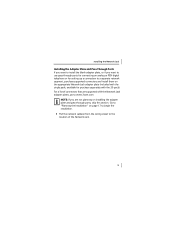
..., or if you are not planning on page 17 to begin the installation. 1 Pull the network cable(s) from the wiring closet to the location of connectors that are supported with the Network Jack adapter plates, go to www.3com.com. available for setting up a connection to "Planning the Installation" on installing the adapter plate...
..., or if you are not planning on page 17 to begin the installation. 1 Pull the network cable(s) from the wiring closet to the location of connectors that are supported with the Network Jack adapter plates, go to www.3com.com. available for setting up a connection to "Planning the Installation" on installing the adapter plate...

Installation Guide
Page 20
...to use the adapter plate that it is labeled with the name of the network cable(s) with the connector(s) you purchased separately. Installation Guide 2 Thread the network cable(s) through the empty slot on the Network Jack. Be sure to test end-to-end system functionality and verify that matches... the manufacturer of your connector(s). 5 Mount the adapter plate to the Network Jack using the two adapter plate screws provided. 16 Be sure to the connector manufacturer's instructions for terminating the cable. Wall To wiring...
...to use the adapter plate that it is labeled with the name of the network cable(s) with the connector(s) you purchased separately. Installation Guide 2 Thread the network cable(s) through the empty slot on the Network Jack. Be sure to test end-to-end system functionality and verify that matches... the manufacturer of your connector(s). 5 Mount the adapter plate to the Network Jack using the two adapter plate screws provided. 16 Be sure to the connector manufacturer's instructions for terminating the cable. Wall To wiring...

Installation Guide
Page 21
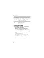
Installing the Network Jack Planning the Installation When installed, the back of some wall and cubicle openings differ, observe the following requirements and recommendations before installing the Network Jack: I Make sure the wall or cubicle opening 1.5 inches. Because the depth of the Network Jack extends into a wall or cubicle opening where the Network Jack is being installed complies with the NEMA-WD6 standard, as described below. 1.750" (44.45 mm) 2.8125" (71.44 mm) 3.28125" (83.31 mm) reference Screw holes 17
Installing the Network Jack Planning the Installation When installed, the back of some wall and cubicle openings differ, observe the following requirements and recommendations before installing the Network Jack: I Make sure the wall or cubicle opening 1.5 inches. Because the depth of the Network Jack extends into a wall or cubicle opening where the Network Jack is being installed complies with the NEMA-WD6 standard, as described below. 1.750" (44.45 mm) 2.8125" (71.44 mm) 3.28125" (83.31 mm) reference Screw holes 17

Installation Guide
Page 22
...NOTE: Some cubicle openings have a depth of the wall or cubicle opening is at least 1.5 inches (3 inches is enough space between the Network Jack and where it sits inside of 1.2 inches. I To ensure proper horizontal cabling functionality, adhere to obtain the minimum 1.5-inch depth. In... this case, install the Network Jack using the extension ring (available for Telecommunications Pathways and Spaces 18 If installing into a wall junction box, make sure there is recommended...
...NOTE: Some cubicle openings have a depth of the wall or cubicle opening is at least 1.5 inches (3 inches is enough space between the Network Jack and where it sits inside of 1.2 inches. I To ensure proper horizontal cabling functionality, adhere to obtain the minimum 1.5-inch depth. In... this case, install the Network Jack using the extension ring (available for Telecommunications Pathways and Spaces 18 If installing into a wall junction box, make sure there is recommended...

Installation Guide
Page 23
...-X port. 19 Refer to the connector manufacturer's instructions for connecting the Network Jack to which the Network Jack is connected is not, install the cabling following these procedures. CAUTION: Make sure the port on the network switch to the network is determined by how your network cable is working. CAUTION: It is done in the previous section, "Setting...
...-X port. 19 Refer to the connector manufacturer's instructions for connecting the Network Jack to which the Network Jack is connected is not, install the cabling following these procedures. CAUTION: Make sure the port on the network switch to the network is determined by how your network cable is working. CAUTION: It is done in the previous section, "Setting...

Installation Guide
Page 24
Installation Guide I If the end of the cable is terminated with a female RJ-45 connector, use the RJ-45 coupler cable included in the package to connect the Network Jack to the network cable (recommended installation.) Wall To wiring closet Network cable 1 2 3 RJ-45 4 coupler cable 20
Installation Guide I If the end of the cable is terminated with a female RJ-45 connector, use the RJ-45 coupler cable included in the package to connect the Network Jack to the network cable (recommended installation.) Wall To wiring closet Network cable 1 2 3 RJ-45 4 coupler cable 20

