Getting Started Guide
Page 24
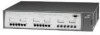
... can be mounted in .) clearance. ■ Air temperature around the Switch does not exceed 40 °C (104 °F). CAUTION: Ensure that you provide a minimum of 25 mm (1 in a standard 19-inch equipment rack, or free-standing. 24 CHAPTER 2: INSTALLING THE SWITCH Package Contents ■ 3Com Switch 4050 (3C17708), Switch 4060 (3C17709) or Switch 4070 (3C17707) ■ CD-ROM ■...
... can be mounted in .) clearance. ■ Air temperature around the Switch does not exceed 40 °C (104 °F). CAUTION: Ensure that you provide a minimum of 25 mm (1 in a standard 19-inch equipment rack, or free-standing. 24 CHAPTER 2: INSTALLING THE SWITCH Package Contents ■ 3Com Switch 4050 (3C17708), Switch 4060 (3C17709) or Switch 4070 (3C17707) ■ CD-ROM ■...

Getting Started Guide
Page 25
...is 2U high and will fit in a clean, air conditioned environment. ■ The AC supply used by the Switch is separate to that used by units that it will not obstruct the air flow through the side panels of the Switch. Rack-mounting 25 ■ The air is as free from dust as shown in..., if the units are placed on a hard flat surface, with a suitable screwdriver. Remove all cables from the underside of conductive (electrical) dust, for example air conditioning units. ■ No more than four Switch units are free-standing. CAUTION: Disconnect all self adhesive pads from the...
...is 2U high and will fit in a clean, air conditioned environment. ■ The AC supply used by the Switch is separate to that used by units that it will not obstruct the air flow through the side panels of the Switch. Rack-mounting 25 ■ The air is as free from dust as shown in..., if the units are placed on a hard flat surface, with a suitable screwdriver. Remove all cables from the underside of conductive (electrical) dust, for example air conditioning units. ■ No more than four Switch units are free-standing. CAUTION: Disconnect all self adhesive pads from the...

Getting Started Guide
Page 60
.... ■ RMON Trap - Should one or more detailed information about RMON, refer to "Chapter 7: Status Monitoring and Statistics" in the Switch Implementation Guide supplied in PDF format on to the list of suggested solutions below. The monitoring system polls the fan status at periodic intervals while... warning messages. If configured, an RMON trap is generated: 1 Power off the unit. 2 Check that the air vents are engaged so that will receive notification of the Switch. If a fan failure warning message is generated and sent to indicate the fan failure. An indication of fan ...
.... ■ RMON Trap - Should one or more detailed information about RMON, refer to "Chapter 7: Status Monitoring and Statistics" in the Switch Implementation Guide supplied in PDF format on to the list of suggested solutions below. The monitoring system polls the fan status at periodic intervals while... warning messages. If configured, an RMON trap is generated: 1 Power off the unit. 2 Check that the air vents are engaged so that will receive notification of the Switch. If a fan failure warning message is generated and sent to indicate the fan failure. An indication of fan ...

Getting Started Guide
Page 61
... with the following: ■ An expansion module or blanking plate fitted. ■ A second PSU or blanking plate fitted 3 Check that the air vents are not obstructed. 4 Check that the ambient temperatures and environmental conditions meet those specified in Appendix C. 5 Check that the front and rear... is running without impacting operations. b Remove the screws securing the fan tray using a suitable screwdriver b Gently slide the fan tray from the Switch. WARNING: Care must not be caused. 5 Replace the fan tray. Keep fingers clear. If the unit has no AC main supply, remove...
... with the following: ■ An expansion module or blanking plate fitted. ■ A second PSU or blanking plate fitted 3 Check that the air vents are not obstructed. 4 Check that the ambient temperatures and environmental conditions meet those specified in Appendix C. 5 Check that the front and rear... is running without impacting operations. b Remove the screws securing the fan tray using a suitable screwdriver b Gently slide the fan tray from the Switch. WARNING: Care must not be caused. 5 Replace the fan tray. Keep fingers clear. If the unit has no AC main supply, remove...

Getting Started Guide
Page 62
... suitable screwdriver b Gently slide the fan tray from the Switch If the fail trap is for the front fan tray: a Open the door where the bulge is received, return the unit. WARNING: Care must not be caused. 2 Check that : ■ The air vents are not obstructed. 3 Replace the fan tray. ... is for the rear fan tray: a Remove the screws securing the fan tray using a suitable screwdriver c Gently slide the fan tray from the Switch CAUTION: A fan tray can be temporarily removed and replaced while the system is running without impacting operations. To do this, remove and reconnect the ...
... suitable screwdriver b Gently slide the fan tray from the Switch If the fail trap is for the front fan tray: a Open the door where the bulge is received, return the unit. WARNING: Care must not be caused. 2 Check that : ■ The air vents are not obstructed. 3 Replace the fan tray. ... is for the rear fan tray: a Remove the screws securing the fan tray using a suitable screwdriver c Gently slide the fan tray from the Switch CAUTION: A fan tray can be temporarily removed and replaced while the system is running without impacting operations. To do this, remove and reconnect the ...