Getting Started Guide
Page 3
Rear View Detail 19 Expansion Module Slot 19 Replaceable Power Supplies (PSUs) 19 Power Socket 20 Replaceable Fan Trays 20 Default Settings 21 2 INSTALLING THE SWITCH Package Contents 24 Choosing a Suitable Site 24 Rack-mounting 25 Placing Units On Top of Hardware Features 13 3Com Switch 40x0 Family - CONTENTS ABOUT THIS GUIDE Conventions 8 Related Documentation 9 Accessing Online...
Rear View Detail 19 Expansion Module Slot 19 Replaceable Power Supplies (PSUs) 19 Power Socket 20 Replaceable Fan Trays 20 Default Settings 21 2 INSTALLING THE SWITCH Package Contents 24 Choosing a Suitable Site 24 Rack-mounting 25 Placing Units On Top of Hardware Features 13 3Com Switch 40x0 Family - CONTENTS ABOUT THIS GUIDE Conventions 8 Related Documentation 9 Accessing Online...
Getting Started Guide
Page 18
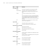
... normally. Off The PSU module is not supplying power and may have failed Red flashing Fan Tray has been removed Off Fan Tray fitted and enabled. Off The Switch software does not support Layer 3. 18 CHAPTER 1: INTRODUCING THE 3COM SWITCH 40X0 FAMILY LED Color Indicates Unit Status LED Green The Switch is a fault with the Power Supply unit.
... normally. Off The PSU module is not supplying power and may have failed Red flashing Fan Tray has been removed Off Fan Tray fitted and enabled. Off The Switch software does not support Layer 3. 18 CHAPTER 1: INTRODUCING THE 3COM SWITCH 40X0 FAMILY LED Color Indicates Unit Status LED Green The Switch is a fault with the Power Supply unit.
Getting Started Guide
Page 19
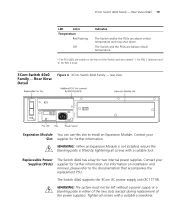
... installed, ensure the blanking plate is fitted by tightening all screws with a suitable tool. For information on the front of the power supplies). The Switch 40x0 supports the 3Com AC power supply unit (3C17718). WARNING: The system must not be left without a power supply or a blanking plate in either of the two slots (except during replacement of the...
... installed, ensure the blanking plate is fitted by tightening all screws with a suitable tool. For information on the front of the power supplies). The Switch 40x0 supports the 3Com AC power supply unit (3C17718). WARNING: The system must not be left without a power supply or a blanking plate in either of the two slots (except during replacement of the...
Getting Started Guide
Page 20
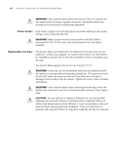
... will also be reduced. Power Socket Each Power Supply automatically adjusts its airflow and temperature will continue to avoid normal cooling being disturbed. WARNING: Mains power must be completed within two minutes to operate after removal. The Switch 40x0 supports the 3Com Fan Tray (3C17717). For.... Although the unit will be affected. 20 CHAPTER 1: INTRODUCING THE 3COM SWITCH 40X0 FAMILY WARNING: Care must be taken when removing a PSU as it has been installed. The replacement of power supplies should be removed from the PSU before removing the PSU. In such...
... will also be reduced. Power Socket Each Power Supply automatically adjusts its airflow and temperature will continue to avoid normal cooling being disturbed. WARNING: Mains power must be completed within two minutes to operate after removal. The Switch 40x0 supports the 3Com Fan Tray (3C17717). For.... Although the unit will be affected. 20 CHAPTER 1: INTRODUCING THE 3COM SWITCH 40X0 FAMILY WARNING: Care must be taken when removing a PSU as it has been installed. The replacement of power supplies should be removed from the PSU before removing the PSU. In such...
Getting Started Guide
Page 29
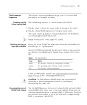
...10/100/1000 Cables The 10/100/1000 ports on the Switch are disabled and Operation of the Switch 4050 and Switch 4060 are Auto-MDIX, that your Switch is by LEDs" on page 58 for Correct During the Power On Self Test, all ports on the front of LEDs... for the second power supply if it is evidence of a problem, see "Solving Problems Indicated by connecting or disconnecting the power cord. The Power-up Sequence 29 The Power-up Sequence The following sequence of steps to power-up the Switch. 3Com Switch 40x0 1 Plug the power cord into your 3Com Switch 40x0 powered-up and ready for...
...10/100/1000 Cables The 10/100/1000 ports on the Switch are disabled and Operation of the Switch 4050 and Switch 4060 are Auto-MDIX, that your Switch is by LEDs" on page 58 for Correct During the Power On Self Test, all ports on the front of LEDs... for the second power supply if it is evidence of a problem, see "Solving Problems Indicated by connecting or disconnecting the power cord. The Power-up Sequence 29 The Power-up Sequence The following sequence of steps to power-up the Switch. 3Com Switch 40x0 1 Plug the power cord into your 3Com Switch 40x0 powered-up and ready for...

Getting Started Guide
Page 58
or ■ A port has failed and has been automatically disabled. If a port fails the Switch passes its Power on Self Test and continues to the supply outlet. Firstly, check whether a temporary fault has occurred by checking that the power cable is quickly flashing Yellow. If the connection is secure and there is quickly flashing yellow...
or ■ A port has failed and has been automatically disabled. If a port fails the Switch passes its Power on Self Test and continues to the supply outlet. Firstly, check whether a temporary fault has occurred by checking that the power cable is quickly flashing Yellow. If the connection is secure and there is quickly flashing yellow...

Getting Started Guide
Page 60
...system polls the fan status at periodic intervals while the unit is generated and sent to "Chapter 7: Status Monitoring and Statistics" in the Switch Implementation Guide supplied in PDF format on to the CLI. Should one or more detailed information about RMON, refer to the management workstation. ■ Command ...failure warning message is provided through the Device Summary table for the specific unit. An expansion module is installed and the unit will not power up . If a fan failure warning message is fully seated in the following ways: ■ RMON Email Notification -
...system polls the fan status at periodic intervals while the unit is generated and sent to "Chapter 7: Status Monitoring and Statistics" in the Switch Implementation Guide supplied in PDF format on to the CLI. Should one or more detailed information about RMON, refer to the management workstation. ■ Command ...failure warning message is provided through the Device Summary table for the specific unit. An expansion module is installed and the unit will not power up . If a fan failure warning message is fully seated in the following ways: ■ RMON Email Notification -

Getting Started Guide
Page 61
...that the air vents are not obstructed. 4 Check that the ambient temperatures and environmental conditions meet those specified in Appendix C. 5 Check that the Switch unit is still received, return the unit. If another fan failure warning message is generated via the Command Line Interface or the Web interface, you... can be left out from the Switch If the fail trap is for a short time after removal. Solving Hardware Problems 61 3 Power cycle the unit. To do this, remove and reconnect the AC mains supply. If the unit has no AC main supply, remove and reconnect the DC RPS...
...that the air vents are not obstructed. 4 Check that the ambient temperatures and environmental conditions meet those specified in Appendix C. 5 Check that the Switch unit is still received, return the unit. If another fan failure warning message is generated via the Command Line Interface or the Web interface, you... can be left out from the Switch If the fail trap is for a short time after removal. Solving Hardware Problems 61 3 Power cycle the unit. To do this, remove and reconnect the AC mains supply. If the unit has no AC main supply, remove and reconnect the DC RPS...

Getting Started Guide
Page 62
...has occurred. 3 If no SNMP fan fail trap or SNMP thermal shutdown trap is received 1 Power cycle the unit. b Remove the screws securing the fan tray using a suitable screwdriver b Gently slide the fan tray from the Switch If the fail trap is for a short time after removal. To do this, remove and... reconnect the AC mains supply (if two PSU's are fitted, remove and reconnect both at the front of the Switch. Unit fails, no , return the unit: If yes, check that the air vents are not obstructed. ■ ...
...has occurred. 3 If no SNMP fan fail trap or SNMP thermal shutdown trap is received 1 Power cycle the unit. b Remove the screws securing the fan tray using a suitable screwdriver b Gently slide the fan tray from the Switch If the fail trap is for a short time after removal. To do this, remove and... reconnect the AC mains supply (if two PSU's are fitted, remove and reconnect both at the front of the Switch. Unit fails, no , return the unit: If yes, check that the air vents are not obstructed. ■ ...
Getting Started Guide
Page 68
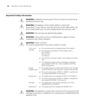
... must be installed below the narrower units. WARNING: If installing a 3Com Switch 40x0 in a stack with an EN60320/IEC320 appliance inlet. WARNING: The appliance coupler (the connector to ensure compliance with SEV/ASE 1011. WARNING: Connect the unit to an earthed power supply to the unit and not the wall plug) must have a rated...
... must be installed below the narrower units. WARNING: If installing a 3Com Switch 40x0 in a stack with an EN60320/IEC320 appliance inlet. WARNING: The appliance coupler (the connector to ensure compliance with SEV/ASE 1011. WARNING: Connect the unit to an earthed power supply to the unit and not the wall plug) must have a rated...

Getting Started Guide
Page 69
...unit and easily accessible. You can be connected to earth (ground). †Impédance à la terre. If your supplies are of the 3Com Switch 40x0 Family, only use a modem which it is fitted by tightening all screws with the secondary connection point labelled Neutral, connected.... WARNING: U.K. WARNING: This unit operates under SELV conditions. Either shielded or unshielded data cables with shielded or unshielded jacks can only remove power from the unit by 230V (2P+T) via an isolation transformer ratio 1:1, with a suitable tool. WARNING: When an Expansion Module is not...
...unit and easily accessible. You can be connected to earth (ground). †Impédance à la terre. If your supplies are of the 3Com Switch 40x0 Family, only use a modem which it is fitted by tightening all screws with the secondary connection point labelled Neutral, connected.... WARNING: U.K. WARNING: This unit operates under SELV conditions. Either shielded or unshielded data cables with shielded or unshielded jacks can only remove power from the unit by 230V (2P+T) via an isolation transformer ratio 1:1, with a suitable tool. WARNING: When an Expansion Module is not...

Getting Started Guide
Page 70
WARNING: The system must be temporarily removed and replaced whilst the system is powered-up . The replacement of power supplies should be left with either of the two slots (except during replacement of performance or procedures other than two minutes or damage to... two minutes to spin for more than those specified herein may be caused. A PSU must be powered once it is running without a power supply or a blanking plate in hazardous laser emissions. WARNING: Mains power must only be removed from the PSU before removing the PSU. The system must be taken when ...
WARNING: The system must be temporarily removed and replaced whilst the system is powered-up . The replacement of power supplies should be left with either of the two slots (except during replacement of performance or procedures other than two minutes or damage to... two minutes to spin for more than those specified herein may be caused. A PSU must be powered once it is running without a power supply or a blanking plate in hazardous laser emissions. WARNING: Mains power must only be removed from the PSU before removing the PSU. The system must be taken when ...
Getting Started Guide
Page 81
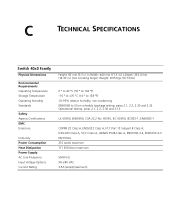
...% relative humidity, non-condensing EN60068 to 3Com schedule (package testing: paras 2.1, 2.2, 2.30 and 2.32. Operational testing: paras 2.1, 2.2, 2.30 and 2.13. C TECHNICAL SPECIFICATIONS Switch 40x0 Family Physical Dimensions Environmental Requirements Operating Temperature Storage Temperature Operating Humidity Standards Safety Agency Certifications EMC Emissions Immunity Power Consumption Heat Dissipation Power Supply AC Line Frequency Input Voltage Options Current...
...% relative humidity, non-condensing EN60068 to 3Com schedule (package testing: paras 2.1, 2.2, 2.30 and 2.32. Operational testing: paras 2.1, 2.2, 2.30 and 2.13. C TECHNICAL SPECIFICATIONS Switch 40x0 Family Physical Dimensions Environmental Requirements Operating Temperature Storage Temperature Operating Humidity Standards Safety Agency Certifications EMC Emissions Immunity Power Consumption Heat Dissipation Power Supply AC Line Frequency Input Voltage Options Current...
Getting Started Guide
Page 87
INDEX A access levels of default users 55 automatic setup 47 3Com Network Supervisor 47 console port 48 C cable 10/100/1000 29 fiber 30 pin-outs 77 CD-ROM ...configuration 29 D default settings 21 users 55 F factory defaults 21 fan tray 20 G GBIC ports 15 H hardware features 13 I installing the Switch 23 prerequisites 25 interconnect cable 27 IP addressing registered 64 IP configuration 39 L LEDs 17 logging in as a default user 55 M management ... cable 77 pin-outs 77 ports 10/100/1000 15 1000BASE-SX 15 GBIC 15 SFP 16 power supplies (PSUs) 19 powering-up a Switch 40x0 Family 29 problem solving 57
INDEX A access levels of default users 55 automatic setup 47 3Com Network Supervisor 47 console port 48 C cable 10/100/1000 29 fiber 30 pin-outs 77 CD-ROM ...configuration 29 D default settings 21 users 55 F factory defaults 21 fan tray 20 G GBIC ports 15 H hardware features 13 I installing the Switch 23 prerequisites 25 interconnect cable 27 IP addressing registered 64 IP configuration 39 L LEDs 17 logging in as a default user 55 M management ... cable 77 pin-outs 77 ports 10/100/1000 15 1000BASE-SX 15 GBIC 15 SFP 16 power supplies (PSUs) 19 powering-up a Switch 40x0 Family 29 problem solving 57

