

Getting Started Guide
Page 3
...TX Ports 14 10/100/1000BASE-T Ports 14 GBIC Ports 14 LEDs 15 Switch 4200 Family - CONTENTS ABOUT THIS GUIDE Conventions 8 Related Documentation 9 Accessing Online Documentation 10 1 INTRODUCING THE SUPERSTACK 3 SWITCH 4200 FAMILY About the Switch 4200 Family 12 Summary of LEDs 24 Connecting a Redundant Power System 25 ...Rear View Detail 17 Power Socket 17 Redundant Power System Socket 17 Console Port 17 Default Settings 18 2 INSTALLING THE SWITCH Package Contents 20 Choosing a Suitable Site 20 Rack-mounting 21 Placing Units On Top of Each Other 23 Stacking Units 23 The Power...
...TX Ports 14 10/100/1000BASE-T Ports 14 GBIC Ports 14 LEDs 15 Switch 4200 Family - CONTENTS ABOUT THIS GUIDE Conventions 8 Related Documentation 9 Accessing Online Documentation 10 1 INTRODUCING THE SUPERSTACK 3 SWITCH 4200 FAMILY About the Switch 4200 Family 12 Summary of LEDs 24 Connecting a Redundant Power System 25 ...Rear View Detail 17 Power Socket 17 Redundant Power System Socket 17 Console Port 17 Default Settings 18 2 INSTALLING THE SWITCH Package Contents 20 Choosing a Suitable Site 20 Rack-mounting 21 Placing Units On Top of Each Other 23 Stacking Units 23 The Power...

Getting Started Guide
Page 4
... Connecting to a Front Panel Port 35 Connecting to the Console Port 38 Viewing Automatically Configured IP Information 42 Using 3Com Network Supervisor 42 Connecting to the Console Port 42 Methods of Managing a Switch 45 Command Line Interface Management 45 Web Interface Management 46 SNMP Management 46 Setting Up Command Line Interface Management...
... Connecting to a Front Panel Port 35 Connecting to the Console Port 38 Viewing Automatically Configured IP Information 42 Using 3Com Network Supervisor 42 Connecting to the Console Port 42 Methods of Managing a Switch 45 Command Line Interface Management 45 Web Interface Management 46 SNMP Management 46 Setting Up Command Line Interface Management...

Getting Started Guide
Page 5
A SAFETY INFORMATION Important Safety Information 60 L'information de Sécurité Importante 62 Wichtige Sicherheitsinformationen 64 B PIN-OUTS Null Modem Cable 67 PC-AT Serial Cable 67 Modem Cable 68 RJ-45 Pin Assignments 68 C TECHNICAL SPECIFICATIONS Switch 4226T (3C17300) 71 Switch 4250T (3C17302) 73 Switch 4228G (3C17304) 74 D OBTAINING SUPPORT FOR YOUR PRODUCT Register Your Product 75 Purchase Value-Added Services 75 Troubleshoot Online 76 Access Software Downloads 76 Telephone Technical Support and Repair 76 Contact Us 77 INDEX REGULATORY NOTICES
A SAFETY INFORMATION Important Safety Information 60 L'information de Sécurité Importante 62 Wichtige Sicherheitsinformationen 64 B PIN-OUTS Null Modem Cable 67 PC-AT Serial Cable 67 Modem Cable 68 RJ-45 Pin Assignments 68 C TECHNICAL SPECIFICATIONS Switch 4226T (3C17300) 71 Switch 4250T (3C17302) 73 Switch 4228G (3C17304) 74 D OBTAINING SUPPORT FOR YOUR PRODUCT Register Your Product 75 Purchase Value-Added Services 75 Troubleshoot Online 76 Access Software Downloads 76 Telephone Technical Support and Repair 76 Contact Us 77 INDEX REGULATORY NOTICES

Getting Started Guide
Page 7
For details on the Switch 4200 26-Port (3C17300A), Switch 4200 50-Port (3C17302A) and Switch 4200 28-Port (3C17304A), refer to the following Switch 4200 Family models: ■ Switch 4226T (3C17300) - 24 10BASE-T/100BASE-TX ports, 2 10/100/1000BASE-T ports ■ Switch 4250T (3C17302) - 48 10BASE-T/100BASE-TX ports, 2 10/100/1000BASE-T ports ■ Switch 4228G (3C17304) - 24...
For details on the Switch 4200 26-Port (3C17300A), Switch 4200 50-Port (3C17302A) and Switch 4200 28-Port (3C17304A), refer to the following Switch 4200 Family models: ■ Switch 4226T (3C17300) - 24 10BASE-T/100BASE-TX ports, 2 10/100/1000BASE-T ports ■ Switch 4250T (3C17302) - 48 10BASE-T/100BASE-TX ports, 2 10/100/1000BASE-T ports ■ Switch 4228G (3C17304) - 24...

Getting Started Guide
Page 9
... guide provides detailed information about the current software release, including new features, modifications, and known problems. There are used to optimize your Switch and how they can be used to: ■ Emphasize a point. ■ Denote a new term at the place where it ...useful, such as: ■ Documentation accompanying the Advanced Redundant Power system. It is supplied in PDF format on the features supported by the Switch. ■ a summary of the software features supported by your network. Examples: From the Help menu, select Contents. Related Documentation 9 Related...
... guide provides detailed information about the current software release, including new features, modifications, and known problems. There are used to optimize your Switch and how they can be used to: ■ Emphasize a point. ■ Denote a new term at the place where it ...useful, such as: ■ Documentation accompanying the Advanced Redundant Power system. It is supplied in PDF format on the features supported by the Switch. ■ a summary of the software features supported by your network. Examples: From the Help menu, select Contents. Related Documentation 9 Related...

Getting Started Guide
Page 10
This is stored in the Docs/implementation directory of the CD-ROM. 3Com recommends that accompanies the Switch. The documentation is accessed using the contents.htm file. ■ The PDF Implementation Guide is to maintain the...the contents page. Accessing Online The CD-ROM supplied with your Switch contains the following online Documentation documentation: ■ SuperStack 3 Switch Management Quick Reference Guide (PDF format) ■ SuperStack 3 Switch Implementation Guide (PDF format) ■ SuperStack 3 Switch Management Interface Reference Guide (HTML format) 1 To access the ...
This is stored in the Docs/implementation directory of the CD-ROM. 3Com recommends that accompanies the Switch. The documentation is accessed using the contents.htm file. ■ The PDF Implementation Guide is to maintain the...the contents page. Accessing Online The CD-ROM supplied with your Switch contains the following online Documentation documentation: ■ SuperStack 3 Switch Management Quick Reference Guide (PDF format) ■ SuperStack 3 Switch Implementation Guide (PDF format) ■ SuperStack 3 Switch Management Interface Reference Guide (HTML format) 1 To access the ...

Getting Started Guide
Page 11
...-Port (3C17302A) and Switch 28-Port (3C17304A), refer to the following topics: ■ About the Switch 4200 Family ■ Switch 4200 Family - It covers summaries of hardware and software features and also the following document: ■ SuperStack 3 Switch 4200 Family Getting Started Guide (part number DUA1730-0AAA03) available for download from the 3Com Web site, www...
...-Port (3C17302A) and Switch 28-Port (3C17304A), refer to the following topics: ■ About the Switch 4200 Family ■ Switch 4200 Family - It covers summaries of hardware and software features and also the following document: ■ SuperStack 3 Switch 4200 Family Getting Started Guide (part number DUA1730-0AAA03) available for download from the 3Com Web site, www...

Getting Started Guide
Page 12
... of : ■ 24 or 48 10BASE-T/100BASE-TX ports ■ 2 10/100/1000BASE-T ports ■ 2 GBIC ports (Switch 4228G only) The Switch provides high-performance workgroups with a backbone to SuperStack Advanced Redundant Power System (ARPS) (3C16071, 3C16071A or 3C16071B) Mounting 19-inch rack...negotiating 10/100/1000BASE-T ports GBIC Auto-negotiating GBIC ports (Switch 4228G only) RPS Support Connects to server connection. 12 CHAPTER 1: INTRODUCING THE SUPERSTACK 3 SWITCH 4200 SERIES About the Switch 4200 Family The Switch 4200 Family are stackable 10/100/1000 Mbps devices which ...
... of : ■ 24 or 48 10BASE-T/100BASE-TX ports ■ 2 10/100/1000BASE-T ports ■ 2 GBIC ports (Switch 4228G only) The Switch provides high-performance workgroups with a backbone to SuperStack Advanced Redundant Power System (ARPS) (3C16071, 3C16071A or 3C16071B) Mounting 19-inch rack...negotiating 10/100/1000BASE-T ports GBIC Auto-negotiating GBIC ports (Switch 4228G only) RPS Support Connects to server connection. 12 CHAPTER 1: INTRODUCING THE SUPERSTACK 3 SWITCH 4200 SERIES About the Switch 4200 Family The Switch 4200 Family are stackable 10/100/1000 Mbps devices which ...

Getting Started Guide
Page 13
... 9 21 10 22 11 23 12 24 Power/ Self Test 1 25 / Up 26 / Down 2 3 Alert 4 Unit Alert LED 10/100/1000BASE-T ports 3C17300 Superstack 3 Switch 4226T Figure 2 Switch 4250T (3C17302) - front view 10BASE-T / 100BASE-TX RJ-45 Ports Unit LEDs Power / Self Test LED 1 25 2 26 3 27 4 28 5 29 6 30 7 31 8 32... 9 33 10 34 11 35 12 36 13 37 14 38 15 39 16 40 17 41 18 42 19 43 3C17302 Superstack 3 Switch 4250T 20 44 21 45 22 46 23 47 24 48 Power/ Self Test 1 Up Down 2 3 Alert 4 Unit 49 50 Alert LED 10/100/1000BASE...
... 9 21 10 22 11 23 12 24 Power/ Self Test 1 25 / Up 26 / Down 2 3 Alert 4 Unit Alert LED 10/100/1000BASE-T ports 3C17300 Superstack 3 Switch 4226T Figure 2 Switch 4250T (3C17302) - front view 10BASE-T / 100BASE-TX RJ-45 Ports Unit LEDs Power / Self Test LED 1 25 2 26 3 27 4 28 5 29 6 30 7 31 8 32... 9 33 10 34 11 35 12 36 13 37 14 38 15 39 16 40 17 41 18 42 19 43 3C17302 Superstack 3 Switch 4250T 20 44 21 45 22 46 23 47 24 48 Power/ Self Test 1 Up Down 2 3 Alert 4 Unit 49 50 Alert LED 10/100/1000BASE...

Getting Started Guide
Page 14
...) and long-haul (LH70) GBIC transceivers in effect, doubles the potential throughput of using GBIC transceivers to provide connectivity between the Switch and remote 1000 Mbps workgroups or to these ports can be transmitted and received simultaneously which, in any combination. The maximum segment ... set these sockets. While auto-negotiation is 100 m (328 ft) over Category 5 twisted pair cable. 10/100/1000BASE-T Ports The Switch has two auto-negotiating 10/100/1000BASE-T ports configured as standard traditional telephone sockets, or to connect the unit to 10BASE-T half duplex,...
...) and long-haul (LH70) GBIC transceivers in effect, doubles the potential throughput of using GBIC transceivers to provide connectivity between the Switch and remote 1000 Mbps workgroups or to these ports can be transmitted and received simultaneously which, in any combination. The maximum segment ... set these sockets. While auto-negotiation is 100 m (328 ft) over Category 5 twisted pair cable. 10/100/1000BASE-T Ports The Switch has two auto-negotiating 10/100/1000BASE-T ports configured as standard traditional telephone sockets, or to connect the unit to 10BASE-T half duplex,...
Getting Started Guide
Page 15
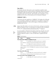
...can be disabled and the flow control setting can be manually configured. 1000BASE-T GBIC's These ports will auto-negotiate to the "SuperStack 3 Switch Management Interface Reference Guide" on the port. Green flashing Packets are negotiated. alternating Off No link is not possible to color. The default...the port. Port Status LEDs 10/100/1000BASE-T ports Green A 1000 Mbps link is present and the port is enabled. About the Switch 4200 Series 15 Fiber GBIC's. For more detailed information, refer to 1000BASE-T, full duplex only. Yellow A 10 Mbps link is present and...
...can be disabled and the flow control setting can be manually configured. 1000BASE-T GBIC's These ports will auto-negotiate to the "SuperStack 3 Switch Management Interface Reference Guide" on the port. Green flashing Packets are negotiated. alternating Off No link is not possible to color. The default...the port. Port Status LEDs 10/100/1000BASE-T ports Green A 1000 Mbps link is present and the port is enabled. About the Switch 4200 Series 15 Fiber GBIC's. For more detailed information, refer to 1000BASE-T, full duplex only. Yellow A 10 Mbps link is present and...

Getting Started Guide
Page 16
... includes running a Power On Self Test). Unit LED number 1 can also indicate a stand-alone Switch. Off The Switch initialization process is present. Yellow The Switch has failed its Power On Self Test. Unit LEDs 1-4 Green When the Switch forms a stack with the Power Supply Unit. Alert LED Green flashing The...port. alternating Off No link is enabled. Yellow A 10 or 100 Mbps link is present and the port is present. Off The Switch Alert LED has been configured via the CLI or Web Interface to Chapter 4 Solving Problems Indicated by LEDs. Power/Self Test LED Green ...
... includes running a Power On Self Test). Unit LED number 1 can also indicate a stand-alone Switch. Off The Switch initialization process is present. Yellow The Switch has failed its Power On Self Test. Unit LEDs 1-4 Green When the Switch forms a stack with the Power Supply Unit. Alert LED Green flashing The...port. alternating Off No link is enabled. Yellow A 10 or 100 Mbps link is present and the port is present. Off The Switch Alert LED has been configured via the CLI or Web Interface to Chapter 4 Solving Problems Indicated by LEDs. Power/Self Test LED Green ...

Getting Started Guide
Page 17
rear view - Console Port The console port allows you can use this socket System Socket to connect a Switch 4200 to connect a terminal and perform remote or local out-of-band management. See "Connecting a Redundant Power System" on page 25. Redundant Power To... Redundant Power System (RPS). Rear View Detail Supply Data Warning Label Console (max) 19200,8,1,N Power Socket Redundant Power System Socket Console Port Power Socket The Switch automatically adjusts its power setting to auto-baud, 8 data bits, no parity and 1 stop bit. The console port uses a standard null modem cable and...
rear view - Console Port The console port allows you can use this socket System Socket to connect a Switch 4200 to connect a terminal and perform remote or local out-of-band management. See "Connecting a Redundant Power System" on page 25. Redundant Power To... Redundant Power System (RPS). Rear View Detail Supply Data Warning Label Console (max) 19200,8,1,N Power Socket Redundant Power System Socket Console Port Power Socket The Switch automatically adjusts its power setting to auto-baud, 8 data bits, no parity and 1 stop bit. The console port uses a standard null modem cable and...
Getting Started Guide
Page 18
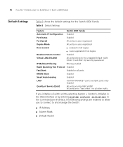
... Enabled Port Status Enabled Port Speed All ports are auto-negotiated Duplex Mode All ports are retained to allow you initialize a Switch unit by selecting System > Control > Initialize in the Web interface or by entering system control initialize in the Command Line Interface... Filtering Filtering enabled Rapid Spanning Tree Protocol Enabled Fast Start: Enabled on all other traffic. 18 CHAPTER 1: INTRODUCING THE SUPERSTACK 3 SWITCH 4200 SERIES Default Settings Table 5 shows the default settings for all ports RMON Alarm Enabled Smart Auto-Sensing Enabled LACP (10/100...
... Enabled Port Status Enabled Port Speed All ports are auto-negotiated Duplex Mode All ports are retained to allow you initialize a Switch unit by selecting System > Control > Initialize in the Web interface or by entering system control initialize in the Command Line Interface... Filtering Filtering enabled Rapid Spanning Tree Protocol Enabled Fast Start: Enabled on all other traffic. 18 CHAPTER 1: INTRODUCING THE SUPERSTACK 3 SWITCH 4200 SERIES Default Settings Table 5 shows the default settings for all ports RMON Alarm Enabled Smart Auto-Sensing Enabled LACP (10/100...

Getting Started Guide
Page 19
...Choosing a Suitable Site ■ Rack-mounting ■ Placing Units On Top of this guide. Avant d'installer ou d'enlever tout composant du Switch 4200 ou d'entamer une procédure de maintenance, lisez les informations relatives à la sécurité qui se trouvent dans ...l'Appendice A de ce guide. Bevor Sie Komponenten aus dem Switch 4200 entfernen oder dem Switch 4200 hinzufuegen oder Instandhaltungsarbeiten verrichten, lesen Sie die Sicherheitsanweisungen, die in Appendix A (Anhang A) in Appendix A of Each Other ...
...Choosing a Suitable Site ■ Rack-mounting ■ Placing Units On Top of this guide. Avant d'installer ou d'enlever tout composant du Switch 4200 ou d'entamer une procédure de maintenance, lisez les informations relatives à la sécurité qui se trouvent dans ...l'Appendice A de ce guide. Bevor Sie Komponenten aus dem Switch 4200 entfernen oder dem Switch 4200 hinzufuegen oder Instandhaltungsarbeiten verrichten, lesen Sie die Sicherheitsanweisungen, die in Appendix A (Anhang A) in Appendix A of Each Other ...
Getting Started Guide
Page 20
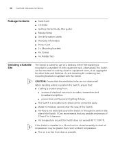
... amplifiers. ■ power lines and fluorescent lighting fixtures ■ The Switch is accessible and cables can be connected easily. ■ Water or moisture cannot enter the case of the Switch. 3Com recommends that the ventilation holes are not obstructed. When deciding where to position... the Switch, ensure that: ■ Cabling is located away from: ■ sources of 25mm (1in.)...
... amplifiers. ■ power lines and fluorescent lighting fixtures ■ The Switch is accessible and cables can be connected easily. ■ Water or moisture cannot enter the case of the Switch. 3Com recommends that the ventilation holes are not obstructed. When deciding where to position... the Switch, ensure that: ■ Cabling is located away from: ■ sources of 25mm (1in.)...

Getting Started Guide
Page 21
... facing towards you. 2 Locate a mounting bracket over the mounting holes on top of one side of the Switch, as shown in most standard 19-inch racks. Rack-mounting 21 ■ The switch is situated away from sources of conductive (electrical) dust, for example, laser printers. ■ The unit ...is installed in a clean, air conditioned environment. ■ The AC supply used by the switch is separate to that used by units that generate high levels of AC noise, for example, air-conditioning units and laser printers. ■ No more...
... facing towards you. 2 Locate a mounting bracket over the mounting holes on top of one side of the Switch, as shown in most standard 19-inch racks. Rack-mounting 21 ■ The switch is situated away from sources of conductive (electrical) dust, for example, laser printers. ■ The unit ...is installed in a clean, air conditioned environment. ■ The AC supply used by the switch is separate to that used by units that generate high levels of AC noise, for example, air-conditioning units and laser printers. ■ No more...

Getting Started Guide
Page 22
The unit information label shows the following: ■ The 3Com product name of the Switch ■ The 3Com 3C number of the Switch ■ The unique MAC address (Ethernet address) of the Switch ■ The serial number of the Switch. 5 Insert the Switch into the 19-inch rack and secure with the mounting brackets. 22 CHAPTER 2: INSTALLING THE...
The unit information label shows the following: ■ The 3Com product name of the Switch ■ The 3Com 3C number of the Switch ■ The unique MAC address (Ethernet address) of the Switch ■ The serial number of the Switch. 5 Insert the Switch into the 19-inch rack and secure with the mounting brackets. 22 CHAPTER 2: INSTALLING THE...

Getting Started Guide
Page 23
... connected to the port marked with 'down' on top of the other , you are mixing a variety of SuperStack® 3 Switch and Hub units, the smaller units must be positioned at the top. 3Com recommends that when you add a new unit to a stack, you should first initialize it to factory default settings. Starting... 4 16 5 17 6 18 7 19 8 20 9 21 10 22 11 23 12 24 Power/ Self Test 1 25 / Up 26 / Down 2 3 Alert 4 Unit 27 27 28 3C17304A Superstack 3 Switch 4200 28-Port 28 1 13 2 14 3 15 4 16 5 17 6 18 7 19 8 20 9 21 10 22 11 23 12 24 Power/ Self Test 1 25 / Up 26...
... connected to the port marked with 'down' on top of the other , you are mixing a variety of SuperStack® 3 Switch and Hub units, the smaller units must be positioned at the top. 3Com recommends that when you add a new unit to a stack, you should first initialize it to factory default settings. Starting... 4 16 5 17 6 18 7 19 8 20 9 21 10 22 11 23 12 24 Power/ Self Test 1 25 / Up 26 / Down 2 3 Alert 4 Unit 27 27 28 3C17304A Superstack 3 Switch 4200 28-Port 28 1 13 2 14 3 15 4 16 5 17 6 18 7 19 8 20 9 21 10 22 11 23 12 24 Power/ Self Test 1 25 / Up 26...

Getting Started Guide
Page 24
... be disabled and its Power On Self Test (POST), which takes approximately 10 seconds. The Switch powers-up the Switch. Checking for operation. 24 CHAPTER 2: INSTALLING THE SWITCH Stack renumbering occurs when another Switch 4200 Family unit is added to the top of an established stack, no effect on the...stack will have no stack renumbering occurs. If however the unit being added takes the stack height above will renumber. ■ Removing a Switch 4200 Family unit from the middle of an existing stack will cause the other end of an existing stack will cause the remaining stack to...
... be disabled and its Power On Self Test (POST), which takes approximately 10 seconds. The Switch powers-up the Switch. Checking for operation. 24 CHAPTER 2: INSTALLING THE SWITCH Stack renumbering occurs when another Switch 4200 Family unit is added to the top of an established stack, no effect on the...stack will have no stack renumbering occurs. If however the unit being added takes the stack height above will renumber. ■ Removing a Switch 4200 Family unit from the middle of an existing stack will cause the other end of an existing stack will cause the remaining stack to...