

Getting Started Guide
Page 1
SuperStack® 3 Switch 4200 Series Getting Started Guide 3C17300 3C17302 3C17304 http://www.3com.com/ Part No. DUA1730-0AAA02 Published October 2002
SuperStack® 3 Switch 4200 Series Getting Started Guide 3C17300 3C17302 3C17304 http://www.3com.com/ Part No. DUA1730-0AAA02 Published October 2002
Getting Started Guide
Page 3
...-T Ports 14 GBIC Ports 14 LEDs 15 Switch 4200 Series - CONTENTS ABOUT THIS GUIDE Conventions 8 Related Documentation 9 Accessing Online Documentation 10 Product Registration 10 Documentation Comments 10 1 INTRODUCING THE SUPERSTACK 3 SWITCH 4200 SERIES About the Switch 4200 Series 12 Summary of Each Other 23... Stacking Units 23 The Power-up Sequence 24 Powering-up the Switch 4200 Series 24 Rear View Detail 17 Power Socket 17 Redundant...
...-T Ports 14 GBIC Ports 14 LEDs 15 Switch 4200 Series - CONTENTS ABOUT THIS GUIDE Conventions 8 Related Documentation 9 Accessing Online Documentation 10 Product Registration 10 Documentation Comments 10 1 INTRODUCING THE SUPERSTACK 3 SWITCH 4200 SERIES About the Switch 4200 Series 12 Summary of Each Other 23... Stacking Units 23 The Power-up Sequence 24 Powering-up the Switch 4200 Series 24 Rear View Detail 17 Power Socket 17 Redundant...
Getting Started Guide
Page 4
... Connecting to a Front Panel Port 35 Connecting to the Console Port 38 Viewing Automatically Configured IP Information 42 Using 3Com Network Supervisor 42 Connecting to the Console Port 42 Methods of Managing a Switch 45 Command Line Interface Management 45 Web Interface Management 46 SNMP Management 46 Setting Up Command Line Interface Management...
... Connecting to a Front Panel Port 35 Connecting to the Console Port 38 Viewing Automatically Configured IP Information 42 Using 3Com Network Supervisor 42 Connecting to the Console Port 42 Methods of Managing a Switch 45 Command Line Interface Management 45 Web Interface Management 46 SNMP Management 46 Setting Up Command Line Interface Management...
Getting Started Guide
Page 5
... Modem Cable 68 RJ-45 Pin Assignments 68 1000BASE-T RJ-45 Pin Assignments 69 C TECHNICAL SPECIFICATIONS Switch 4226T (3C17300) 71 Switch 4250T (3C17302) 73 Switch 4228G (3C17304) 74 D TECHNICAL SUPPORT Online Technical Services 75 World Wide Web Site 75 3Com Knowledgebase Web Services 76 3Com FTP Site 76 Support from Your Network Supplier 76 Support from...
... Modem Cable 68 RJ-45 Pin Assignments 68 1000BASE-T RJ-45 Pin Assignments 69 C TECHNICAL SPECIFICATIONS Switch 4226T (3C17300) 71 Switch 4250T (3C17302) 73 Switch 4228G (3C17304) 74 D TECHNICAL SUPPORT Online Technical Services 75 World Wide Web Site 75 3Com Knowledgebase Web Services 76 3Com FTP Site 76 Support from Your Network Supplier 76 Support from...
Getting Started Guide
Page 7
...3com.com/ This guide is intended for installing and setting up network equipment; ABOUT THIS GUIDE This guide provides all the information you need to all Switch 4200 Series models: ■ Switch 4226T (3C17300) - 24 10BASE-T/100BASE-TX ports, 2 10/100/1000BASE-T ports ■ Switch 4250T (3C17302...) - 48 10BASE-T/100BASE-TX ports, 2 10/100/1000BASE-T ports ■ Switch 4228G (3C17304) - 24 10BASE-T/100BASE...
...3com.com/ This guide is intended for installing and setting up network equipment; ABOUT THIS GUIDE This guide provides all the information you need to all Switch 4200 Series models: ■ Switch 4226T (3C17300) - 24 10BASE-T/100BASE-TX ports, 2 10/100/1000BASE-T ports ■ Switch 4250T (3C17302...) - 48 10BASE-T/100BASE-TX ports, 2 10/100/1000BASE-T ports ■ Switch 4228G (3C17304) - 24 10BASE-T/100BASE...
Getting Started Guide
Page 9
... There are other publications you to optimize your network. It is supplied in HTML format on the CD-ROM that accompanies the Switch. ■ Release Notes These notes provide information about the web interface and command line interface that enable you may find useful...as: ■ Documentation accompanying the Advanced Redundant Power system. ■ Documentation accompanying 3Com Network Supervisor. This is supplied in PDF format on the CD-ROM that accompanies the Switch. ■ SuperStack 3 Switch Management Quick Reference Guide This guide contains: ■ a list of the software...
... There are other publications you to optimize your network. It is supplied in HTML format on the CD-ROM that accompanies the Switch. ■ Release Notes These notes provide information about the web interface and command line interface that enable you may find useful...as: ■ Documentation accompanying the Advanced Redundant Power system. ■ Documentation accompanying 3Com Network Supervisor. This is supplied in PDF format on the CD-ROM that accompanies the Switch. ■ SuperStack 3 Switch Management Quick Reference Guide This guide contains: ■ a list of the software...
Getting Started Guide
Page 10
... your CD-ROM drive. Please e-mail comments about this document to 3Com at: pddtechpubs_comments@3com.com Please include the following online Documentation documentation: ■ SuperStack 3 Switch Implementation Guide (PDF format) ■ SuperStack 3 Switch Management Interface Reference Guide (HTML format) 1 To access the documentation insert... the CD-ROM into your SuperStack 3 Switch 4200 on the 3Com Web site: http://3com.com/register Documentation Comments Your suggestions are very important to us. They will need to access the...
... your CD-ROM drive. Please e-mail comments about this document to 3Com at: pddtechpubs_comments@3com.com Please include the following online Documentation documentation: ■ SuperStack 3 Switch Implementation Guide (PDF format) ■ SuperStack 3 Switch Management Interface Reference Guide (HTML format) 1 To access the documentation insert... the CD-ROM into your SuperStack 3 Switch 4200 on the 3Com Web site: http://3com.com/register Documentation Comments Your suggestions are very important to us. They will need to access the...

Getting Started Guide
Page 11
It covers summaries of hardware and software features and also the following topics: ■ About the Switch 4200 Series ■ Switch 4200 Series - 1 INTRODUCING THE SUPERSTACK 3 SWITCH 4200 SERIES This chapter contains introductory information about the Switch 4200 Series and how it can be used in your network. Front View Detail ■ Switch 4200 Series - Rear View Detail ■ Default Settings
It covers summaries of hardware and software features and also the following topics: ■ About the Switch 4200 Series ■ Switch 4200 Series - 1 INTRODUCING THE SUPERSTACK 3 SWITCH 4200 SERIES This chapter contains introductory information about the Switch 4200 Series and how it can be used in your network. Front View Detail ■ Switch 4200 Series - Rear View Detail ■ Default Settings
Getting Started Guide
Page 12
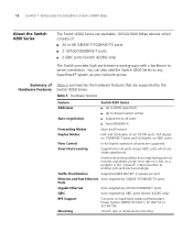
...-T/100BASE-TX ports ■ 2 10/100/1000BASE-T ports ■ 2 GBIC ports (Switch 4228G only) The Switch provides high-performance workgroups with a backbone to server connection. Table 3 Hardware features Feature Switch 4200 Series Addresses ■ Up to 8000 supported ■ Up to any SuperStack®.../1000BASE-T ports GBIC Auto-negotiating GBIC ports (Switch 4228G only) RPS Support Connects to another port and react accordingly. 12 CHAPTER 1: INTRODUCING THE SUPERSTACK 3 SWITCH 4200 SERIES About the Switch 4200 Series The Switch 4200 Series are stackable 10/100/1000 Mbps ...
...-T/100BASE-TX ports ■ 2 10/100/1000BASE-T ports ■ 2 GBIC ports (Switch 4228G only) The Switch provides high-performance workgroups with a backbone to server connection. Table 3 Hardware features Feature Switch 4200 Series Addresses ■ Up to 8000 supported ■ Up to any SuperStack®.../1000BASE-T ports GBIC Auto-negotiating GBIC ports (Switch 4228G only) RPS Support Connects to another port and react accordingly. 12 CHAPTER 1: INTRODUCING THE SUPERSTACK 3 SWITCH 4200 SERIES About the Switch 4200 Series The Switch 4200 Series are stackable 10/100/1000 Mbps ...
Getting Started Guide
Page 13
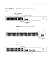
... 9 21 10 22 11 23 12 24 Power/ Self Test 1 25 / Up 26 / Down 2 3 Alert 4 Unit Alert LED 10/100/1000BASE-T ports 3C17300 Superstack 3 Switch 4226T Figure 2 Switch 4250T (3C17302) - front view 10BASE-T / 100BASE-TX RJ-45 Ports Unit LEDs Power / Self Test LED 1 13 2 14 3 15 4 16 5 17 6 18 7 19 8 20 9 21... 5 29 6 30 7 31 8 32 9 33 10 34 11 35 12 36 13 37 14 38 15 39 16 40 17 41 18 42 19 43 3C17302 Superstack 3 Switch 4250T 20 44 21 45 22 46 23 47 24 48 Power/ Self Test 1 Up Down 2 3 Alert 4 Unit 49 50 Alert LED 10/100...
... 9 21 10 22 11 23 12 24 Power/ Self Test 1 25 / Up 26 / Down 2 3 Alert 4 Unit Alert LED 10/100/1000BASE-T ports 3C17300 Superstack 3 Switch 4226T Figure 2 Switch 4250T (3C17302) - front view 10BASE-T / 100BASE-TX RJ-45 Ports Unit LEDs Power / Self Test LED 1 13 2 14 3 15 4 16 5 17 6 18 7 19 8 20 9 21... 5 29 6 30 7 31 8 32 9 33 10 34 11 35 12 36 13 37 14 38 15 39 16 40 17 41 18 42 19 43 3C17302 Superstack 3 Switch 4250T 20 44 21 45 22 46 23 47 24 48 Power/ Self Test 1 Up Down 2 3 Alert 4 Unit 49 50 Alert LED 10/100...
Getting Started Guide
Page 14
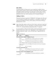
... shielded or unshielded jacks can manually set these sockets. These ports provide 10/100/1000 Mbps full duplex connections to the SuperStack 3 Switch 4228G only. The two GBIC ports support Category 5 twisted pair cable and fiber Gigabit Ethernet short-wave (SX), long-wave (LX...) and long-haul (LH70) GBIC transceivers in effect, doubles the potential throughput of using GBIC transceivers to provide connectivity between the Switch and remote 1000 Mbps workgroups or to a traditional PBX or public telephone network. They cannot be transmitted and received simultaneously which, in...
... shielded or unshielded jacks can manually set these sockets. These ports provide 10/100/1000 Mbps full duplex connections to the SuperStack 3 Switch 4228G only. The two GBIC ports support Category 5 twisted pair cable and fiber Gigabit Ethernet short-wave (SX), long-wave (LX...) and long-haul (LH70) GBIC transceivers in effect, doubles the potential throughput of using GBIC transceivers to provide connectivity between the Switch and remote 1000 Mbps workgroups or to a traditional PBX or public telephone network. They cannot be transmitted and received simultaneously which, in...
Getting Started Guide
Page 15
... Packets are being transmitted/received on the port. LEDs Table 4 lists LEDs visible on the CD-ROM that is negotiated with the Switch. The default state for flow control support, effectively enabling or disabling flow control. Although it is not possible to color. alternating Off...Mbps link is present and the port is disabled. For more detailed information, refer to the "SuperStack 3 Switch Management Interface Reference Guide" on the front of the Switch, and how to read their status according to disable auto-negotiation it is enabled. Because the speed and duplex...
... Packets are being transmitted/received on the port. LEDs Table 4 lists LEDs visible on the CD-ROM that is negotiated with the Switch. The default state for flow control support, effectively enabling or disabling flow control. Although it is not possible to color. alternating Off...Mbps link is present and the port is disabled. For more detailed information, refer to the "SuperStack 3 Switch Management Interface Reference Guide" on the front of the Switch, and how to read their status according to disable auto-negotiation it is enabled. Because the speed and duplex...
Getting Started Guide
Page 16
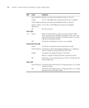
... indicates the position of the unit in the stack and that a link is enabled. Off The Switch Alert LED has been configured via the CLI or Web Interface to flash. Off The Switch initialization process is powered-up and operating normally. Green / Yellow A 10, 100 or 1000 Mbps... Off No link is initializing (which includes running a Power On Self Test). Green flashing The Switch is either downloading software or is present. Alert LED Green flashing The Switch Alert LED has been configured via the CLI or Web Interface to Chapter 4 Solving Problems Indicated by LEDs. Unit ...
... indicates the position of the unit in the stack and that a link is enabled. Off The Switch Alert LED has been configured via the CLI or Web Interface to flash. Off The Switch initialization process is powered-up and operating normally. Green / Yellow A 10, 100 or 1000 Mbps... Off No link is initializing (which includes running a Power On Self Test). Green flashing The Switch is either downloading software or is present. Alert LED Green flashing The Switch Alert LED has been configured via the CLI or Web Interface to Chapter 4 Solving Problems Indicated by LEDs. Unit ...

Getting Started Guide
Page 17
...uses a standard null modem cable and is set to any supply voltage in the range 90-240 VAC. About the Switch 4200 Series 17 Switch 4200 Series Figure 4 Switch 4200 Series - Redundant Power To protect against internal power supply failure, you to a SuperStack Advanced Redundant Power System (RPS...). Console Port The console port allows you can use this socket System Socket to connect a Switch 4200 to connect a terminal and perform remote or local out-of-band management. Rear View Detail Supply Data Warning Label Console (max) 19200...
...uses a standard null modem cable and is set to any supply voltage in the range 90-240 VAC. About the Switch 4200 Series 17 Switch 4200 Series Figure 4 Switch 4200 Series - Redundant Power To protect against internal power supply failure, you to a SuperStack Advanced Redundant Power System (RPS...). Console Port The console port allows you can use this socket System Socket to connect a Switch 4200 to connect a terminal and perform remote or local out-of-band management. Rear View Detail Supply Data Warning Label Console (max) 19200...
Getting Started Guide
Page 18
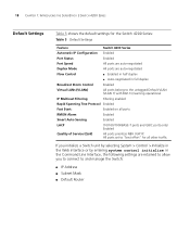
...Tree Protocol Enabled Fast Start: Enabled on all other traffic. All ports set to "best effort" for the Switch 4200 Series: Table 5 Default Settings Feature Switch 4200 Series Automatic IP Configuration Enabled Port Status Enabled Port Speed All ports are auto-negotiated Duplex Mode All ...ports are retained to allow you initialize a Switch unit by selecting System > Control > Initialize in the Web interface or by entering system control initialize in the Command Line Interface,...
...Tree Protocol Enabled Fast Start: Enabled on all other traffic. All ports set to "best effort" for the Switch 4200 Series: Table 5 Default Settings Feature Switch 4200 Series Automatic IP Configuration Enabled Port Status Enabled Port Speed All ports are auto-negotiated Duplex Mode All ...ports are retained to allow you initialize a Switch unit by selecting System > Control > Initialize in the Web interface or by entering system control initialize in the Command Line Interface,...
Getting Started Guide
Page 19
... la sécurité qui se trouvent dans l'Appendice A de ce guide. VORSICHT: Sicherheitsinformationen. 2 INSTALLING THE SWITCH This chapter contains the information you must read the safety information provided in diesem Handbuch aufgefuehrt sind. AVERTISSEMENT: Consignes de ...sécurité. Bevor Sie Komponenten aus dem Switch 4200 entfernen oder dem Switch 4200 hinzufuegen oder Instandhaltungsarbeiten verrichten, lesen Sie die Sicherheitsanweisungen, die in Appendix A (Anhang A) in Appendix ...
... la sécurité qui se trouvent dans l'Appendice A de ce guide. VORSICHT: Sicherheitsinformationen. 2 INSTALLING THE SWITCH This chapter contains the information you must read the safety information provided in diesem Handbuch aufgefuehrt sind. AVERTISSEMENT: Consignes de ...sécurité. Bevor Sie Komponenten aus dem Switch 4200 entfernen oder dem Switch 4200 hinzufuegen oder Instandhaltungsarbeiten verrichten, lesen Sie die Sicherheitsanweisungen, die in Appendix A (Anhang A) in Appendix ...
Getting Started Guide
Page 20
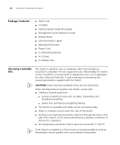
... such as an aggregator for use on a desktop, either free standing or mounted in a standard 19-inch equipment rack. Alternatively, the Switch can be mounted in a wiring closet or equipment room, as radios, transmitters and broadband amplifiers. ■ power lines and fluorescent lighting fixtures ■... temperature around the Switch or through the vents in a 19-inch rack or closed assembly its local air temperature may be connected easily. ■ Water or moisture cannot enter the case of the Switch. ■ Air-flow is installed in the side of the Switch. 3Com recommends that the ...
... such as an aggregator for use on a desktop, either free standing or mounted in a standard 19-inch equipment rack. Alternatively, the Switch can be mounted in a wiring closet or equipment room, as radios, transmitters and broadband amplifiers. ■ power lines and fluorescent lighting fixtures ■... temperature around the Switch or through the vents in a 19-inch rack or closed assembly its local air temperature may be connected easily. ■ Water or moisture cannot enter the case of the Switch. ■ Air-flow is installed in the side of the Switch. 3Com recommends that the ...
Getting Started Guide
Page 21
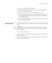
...hard flat surface, with the front facing towards you. 2 Locate a mounting bracket over the mounting holes on top of one side of the Switch, as possible. ■ The switch is situated away from sources of conductive (electrical) dust, for example, laser printers. ■ The unit is installed in a clean, ...air conditioned environment. ■ The AC supply used by the switch is separate to that used by units that generate high levels of AC noise, for example, air-conditioning units and laser printers. ■ No more...
...hard flat surface, with the front facing towards you. 2 Locate a mounting bracket over the mounting holes on top of one side of the Switch, as possible. ■ The switch is situated away from sources of conductive (electrical) dust, for example, laser printers. ■ The unit is installed in a clean, ...air conditioned environment. ■ The AC supply used by the switch is separate to that used by units that generate high levels of AC noise, for example, air-conditioning units and laser printers. ■ No more...
Getting Started Guide
Page 22
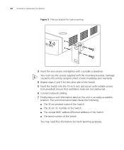
... The unit information label shows the following: ■ The 3Com product name of the Switch ■ The 3Com 3C number of the Switch ■ The unique MAC address (Ethernet address) of the Switch ■ The serial number of the Switch. 5 Insert the Switch into the 19-inch rack and secure with the mounting brackets...Damage caused to the unit by using incorrect screws invalidates your warranty. 4 Repeat steps 2 and 3 for the other side of the Switch You may need this information for rack-mounting 3 Insert the two screws and tighten with a suitable screwdriver. 22 CHAPTER 2: INSTALLING THE...
... The unit information label shows the following: ■ The 3Com product name of the Switch ■ The 3Com 3C number of the Switch ■ The unique MAC address (Ethernet address) of the Switch ■ The serial number of the Switch. 5 Insert the Switch into the 19-inch rack and secure with the mounting brackets...Damage caused to the unit by using incorrect screws invalidates your warranty. 4 Repeat steps 2 and 3 for the other side of the Switch You may need this information for rack-mounting 3 Insert the two screws and tighten with a suitable screwdriver. 22 CHAPTER 2: INSTALLING THE...
Getting Started Guide
Page 23
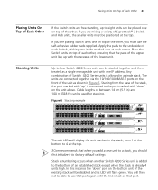
...9 33 10 34 11 35 12 36 13 37 14 38 15 39 16 40 17 41 18 42 19 43 3C17302 Superstack 3 Switch 4250T 20 44 21 45 22 46 23 47 24 48 Power/ Self Test 1 Up Down 2 3 Alert 4 ...when another Switch 4200 Series unit is already 4 units high. If you must be stacked together and then treated as shown in ) and 100 m (328 ft) can be positioned at the top. 3Com recommends that ...lost on top of the unit as a single manageable unit with the recesses of SuperStack® 3 Switch and Hub units, the smaller units must use the self-adhesive rubber pads supplied. You will flash green...
...9 33 10 34 11 35 12 36 13 37 14 38 15 39 16 40 17 41 18 42 19 43 3C17302 Superstack 3 Switch 4250T 20 44 21 45 22 46 23 47 24 48 Power/ Self Test 1 Up Down 2 3 Alert 4 ...when another Switch 4200 Series unit is already 4 units high. If you must be stacked together and then treated as shown in ) and 100 m (328 ft) can be positioned at the top. 3Com recommends that ...lost on top of the unit as a single manageable unit with the recesses of SuperStack® 3 Switch and Hub units, the smaller units must use the self-adhesive rubber pads supplied. You will flash green...