
Getting Started Guide
Page 1
DUA1730-0AAA02 Published October 2002 SuperStack® 3 Switch 4200 Series Getting Started Guide 3C17300 3C17302 3C17304 http://www.3com.com/ Part No.
DUA1730-0AAA02 Published October 2002 SuperStack® 3 Switch 4200 Series Getting Started Guide 3C17300 3C17302 3C17304 http://www.3com.com/ Part No.
Getting Started Guide
Page 3
... 12 Summary of Each Other 23 Stacking Units 23 The Power-up Sequence 24 Powering-up the Switch 4200 Series 24 Rear View Detail 17 Power Socket 17 Redundant Power System Socket 17 Console Port 17 Default Settings 18 2 INSTALLING THE SWITCH Package Contents ...20 Choosing a Suitable Site 20 Rack-mounting 21 Placing Units On Top of Hardware Features 12 Switch 4200 Series - Front View Detail 13 10BASE-T/ 100BASE-TX Ports 14 10/100/1000BASE-T Ports 14 GBIC Ports 14 LEDs 15 Switch...
... 12 Summary of Each Other 23 Stacking Units 23 The Power-up Sequence 24 Powering-up the Switch 4200 Series 24 Rear View Detail 17 Power Socket 17 Redundant Power System Socket 17 Console Port 17 Default Settings 18 2 INSTALLING THE SWITCH Package Contents ...20 Choosing a Suitable Site 20 Rack-mounting 21 Placing Units On Top of Hardware Features 12 Switch 4200 Series - Front View Detail 13 10BASE-T/ 100BASE-TX Ports 14 10/100/1000BASE-T Ports 14 GBIC Ports 14 LEDs 15 Switch...
Getting Started Guide
Page 7
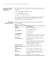
ABOUT THIS GUIDE This guide provides all the information you need to all Switch 4200 Series models: ■ Switch 4226T (3C17300) - 24 10BASE-T/100BASE-TX ports, 2 10/100/1000BASE-T ports ■ Switch 4250T (3C17302) - 48 10BASE-T/100BASE-TX ports, 2 10/100/1000BASE-T ports ■ Switch 4228G (3C17304) - 24 10BASE... (Local Area Networks). If the information in Adobe Acrobat Reader Portable Document Format (PDF) or HTML on the 3Com World Wide Web site: http://www.3com.com/ Most user guides and release notes are responsible for use with your product differ from the information in this...
ABOUT THIS GUIDE This guide provides all the information you need to all Switch 4200 Series models: ■ Switch 4226T (3C17300) - 24 10BASE-T/100BASE-TX ports, 2 10/100/1000BASE-T ports ■ Switch 4250T (3C17302) - 48 10BASE-T/100BASE-TX ports, 2 10/100/1000BASE-T ports ■ Switch 4228G (3C17304) - 24 10BASE... (Local Area Networks). If the information in Adobe Acrobat Reader Portable Document Format (PDF) or HTML on the 3Com World Wide Web site: http://www.3com.com/ Most user guides and release notes are responsible for use with your product differ from the information in this...
Getting Started Guide
Page 10
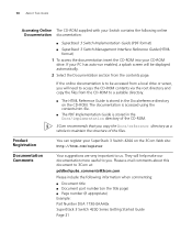
...You can register your SuperStack 3 Switch 4200 on the CD-ROM. Please e-mail comments about this document to maintain the structure of the CD-ROM. 3Com recommends that you copy the Docs/reference directory as a whole to 3Com at: pddtechpubs_comments@3com.com Please include the following online Documentation...Document part number (on the title page) ■ Page number (if appropriate) Example: Part Number DUA 1730-0AAA0x SuperStack 3 Switch 4200 Series Getting Started Guide Page 21 The documentation is accessed using the contents.htm file. ■ The PDF Implementation Guide is stored in ...
...You can register your SuperStack 3 Switch 4200 on the CD-ROM. Please e-mail comments about this document to maintain the structure of the CD-ROM. 3Com recommends that you copy the Docs/reference directory as a whole to 3Com at: pddtechpubs_comments@3com.com Please include the following online Documentation...Document part number (on the title page) ■ Page number (if appropriate) Example: Part Number DUA 1730-0AAA0x SuperStack 3 Switch 4200 Series Getting Started Guide Page 21 The documentation is accessed using the contents.htm file. ■ The PDF Implementation Guide is stored in ...
Getting Started Guide
Page 11
Front View Detail ■ Switch 4200 Series - Rear View Detail ■ Default Settings 1 INTRODUCING THE SUPERSTACK 3 SWITCH 4200 SERIES This chapter contains introductory information about the Switch 4200 Series and how it can be used in your network. It covers summaries of hardware and software features and also the following topics: ■ About the Switch 4200 Series ■ Switch 4200 Series -
Front View Detail ■ Switch 4200 Series - Rear View Detail ■ Default Settings 1 INTRODUCING THE SUPERSTACK 3 SWITCH 4200 SERIES This chapter contains introductory information about the Switch 4200 Series and how it can be used in your network. It covers summaries of hardware and software features and also the following topics: ■ About the Switch 4200 Series ■ Switch 4200 Series -
Getting Started Guide
Page 12
... are stackable 10/100/1000 Mbps devices which are supported by the Switch 4200 Series. You can also add the Switch 4200 Series to SuperStack Advanced Redundant Power System (ARPS) (3C16071, 3C16071A or 3C16071B) Mounting 19-inch rack or stand-alone mounting Full duplex on 1000BASE-T ports ... Switch provides high-performance workgroups with a backbone to 64 permanent entries Auto-negotiation ■ Supported on all 10/100 ports. Table 3 Hardware features Feature Switch 4200 Series Addresses ■ Up to 8000 supported ■ Up to server connection.
... are stackable 10/100/1000 Mbps devices which are supported by the Switch 4200 Series. You can also add the Switch 4200 Series to SuperStack Advanced Redundant Power System (ARPS) (3C16071, 3C16071A or 3C16071B) Mounting 19-inch rack or stand-alone mounting Full duplex on 1000BASE-T ports ... Switch provides high-performance workgroups with a backbone to 64 permanent entries Auto-negotiation ■ Supported on all 10/100 ports. Table 3 Hardware features Feature Switch 4200 Series Addresses ■ Up to 8000 supported ■ Up to server connection.
Getting Started Guide
Page 13
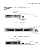
...24 48 Power/ Self Test 1 Up Down 2 3 Alert 4 Unit 49 50 Alert LED 10/100/1000BASE-T ports Figure 3 Switch 4228G (3C17304) - About the Switch 4200 Series 13 Switch 4200 Series - front view 10BASE-T / 100BASE-TX RJ-45 Ports Unit LEDs Power / Self Test LED 1 13 2 14 3 15 4 16 5 17 6 18 7 ... 23 12 24 Power/ Self Test 1 25 / Up 26 / Down 2 3 Alert 4 Unit Alert LED 10/100/1000BASE-T ports 3C17300 Superstack 3 Switch 4226T Figure 2 Switch 4250T (3C17302) - front view 10BASE-T / 100BASE-TX RJ-45 Ports Unit LEDs Power / Self Test LED 1 13 2 14 3 15 4 16 5 17 6 18 7 19 8 20 9 ...
...24 48 Power/ Self Test 1 Up Down 2 3 Alert 4 Unit 49 50 Alert LED 10/100/1000BASE-T ports Figure 3 Switch 4228G (3C17304) - About the Switch 4200 Series 13 Switch 4200 Series - front view 10BASE-T / 100BASE-TX RJ-45 Ports Unit LEDs Power / Self Test LED 1 13 2 14 3 15 4 16 5 17 6 18 7 ... 23 12 24 Power/ Self Test 1 25 / Up 26 / Down 2 3 Alert 4 Unit Alert LED 10/100/1000BASE-T ports 3C17300 Superstack 3 Switch 4226T Figure 2 Switch 4250T (3C17302) - front view 10BASE-T / 100BASE-TX RJ-45 Ports Unit LEDs Power / Self Test LED 1 13 2 14 3 15 4 16 5 17 6 18 7 19 8 20 9 ...
Getting Started Guide
Page 14
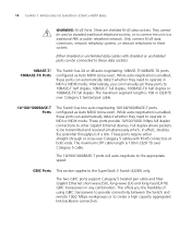
... connection. Only connect RJ-45 data connectors, network telephony systems, or network telephones to the SuperStack 3 Switch 4228G only. 14 CHAPTER 1: INTRODUCING THE SUPERSTACK 3 SWITCH 4200 SERIES WARNING: RJ-45 Ports. While auto-negotiation is enabled, these sockets.
... connection. Only connect RJ-45 data connectors, network telephony systems, or network telephones to the SuperStack 3 Switch 4228G only. 14 CHAPTER 1: INTRODUCING THE SUPERSTACK 3 SWITCH 4200 SERIES WARNING: RJ-45 Ports. While auto-negotiation is enabled, these sockets.
Getting Started Guide
Page 15
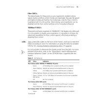
... Green A 100 Mbps link is present and the port is enabled. Yellow A 10 Mbps link is present and the port is enabled. About the Switch 4200 Series 15 Fiber GBIC's. The default state for problem solving, see "Solving Problems Indicated by the media type, only the flow control is auto-negotiation...
... Green A 100 Mbps link is present and the port is enabled. Yellow A 10 Mbps link is present and the port is enabled. About the Switch 4200 Series 15 Fiber GBIC's. The default state for problem solving, see "Solving Problems Indicated by the media type, only the flow control is auto-negotiation...
Getting Started Guide
Page 16
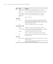
...link is initializing (which includes running a Power On Self Test). Power/Self Test LED Green The Switch is a fault with other Switch 4200 Series units the LED indicates the position of the unit in the stack and that a link is present. Off The Switch is not receiving... been configured via the CLI or Web Interface to Chapter 4 Solving Problems Indicated by LEDs. 16 CHAPTER 1: INTRODUCING THE SUPERSTACK 3 SWITCH 4200 SERIES LED Color Indicates Green flashing Packets are being transmitted/received on the port. Off The Switch initialization process is enabled. Yellow The Switch...
...link is initializing (which includes running a Power On Self Test). Power/Self Test LED Green The Switch is a fault with other Switch 4200 Series units the LED indicates the position of the unit in the stack and that a link is present. Off The Switch is not receiving... been configured via the CLI or Web Interface to Chapter 4 Solving Problems Indicated by LEDs. 16 CHAPTER 1: INTRODUCING THE SUPERSTACK 3 SWITCH 4200 SERIES LED Color Indicates Green flashing Packets are being transmitted/received on the port. Off The Switch initialization process is enabled. Yellow The Switch...

Getting Started Guide
Page 17
... a SuperStack Advanced Redundant Power System (RPS). Console Port The console port allows you can use this socket System Socket to connect a Switch 4200 to connect a terminal and perform remote or local out-of-band management. The console port uses a standard null modem cable and is set... to any supply voltage in the range 90-240 VAC. About the Switch 4200 Series 17 Switch 4200 Series Figure 4 Switch 4200 Series - Rear View Detail Supply Data Warning Label Console (max) 19200,8,1,N Power Socket Redundant Power System Socket Console Port...
... a SuperStack Advanced Redundant Power System (RPS). Console Port The console port allows you can use this socket System Socket to connect a Switch 4200 to connect a terminal and perform remote or local out-of-band management. The console port uses a standard null modem cable and is set... to any supply voltage in the range 90-240 VAC. About the Switch 4200 Series 17 Switch 4200 Series Figure 4 Switch 4200 Series - Rear View Detail Supply Data Warning Label Console (max) 19200,8,1,N Power Socket Redundant Power System Socket Console Port...
Getting Started Guide
Page 18
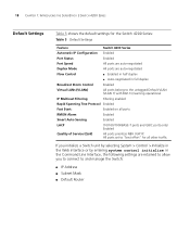
18 CHAPTER 1: INTRODUCING THE SUPERSTACK 3 SWITCH 4200 SERIES Default Settings Table 5 shows the default settings for all ports RMON Alarm Enabled Smart Auto-Sensing Enabled LACP (10/100/1000BASE-T ports and GBIC ... and manage the Switch: ■ IP Address ■ Subnet Mask ■ Default Router All ports set to "best effort" for the Switch 4200 Series: Table 5 Default Settings Feature Switch 4200 Series Automatic IP Configuration Enabled Port Status Enabled Port Speed All ports are auto-negotiated Duplex Mode All ports are auto-negotiated...
18 CHAPTER 1: INTRODUCING THE SUPERSTACK 3 SWITCH 4200 SERIES Default Settings Table 5 shows the default settings for all ports RMON Alarm Enabled Smart Auto-Sensing Enabled LACP (10/100/1000BASE-T ports and GBIC ... and manage the Switch: ■ IP Address ■ Subnet Mask ■ Default Router All ports set to "best effort" for the Switch 4200 Series: Table 5 Default Settings Feature Switch 4200 Series Automatic IP Configuration Enabled Port Status Enabled Port Speed All ports are auto-negotiated Duplex Mode All ports are auto-negotiated...
Getting Started Guide
Page 19
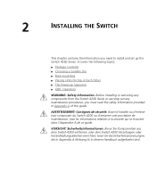
...se trouvent dans l'Appendice A de ce guide. AVERTISSEMENT: Consignes de sécurité. Bevor Sie Komponenten aus dem Switch 4200 entfernen oder dem Switch 4200 hinzufuegen oder Instandhaltungsarbeiten verrichten, lesen Sie die Sicherheitsanweisungen, die in Appendix A (Anhang A) in Appendix A of Each Other &#...9632; The Power-up the Switch 4200 Series. It covers the following topics: ■ Package Contents ■ Choosing a Suitable Site ■ Rack-mounting ■ Placing ...
...se trouvent dans l'Appendice A de ce guide. AVERTISSEMENT: Consignes de sécurité. Bevor Sie Komponenten aus dem Switch 4200 entfernen oder dem Switch 4200 hinzufuegen oder Instandhaltungsarbeiten verrichten, lesen Sie die Sicherheitsanweisungen, die in Appendix A (Anhang A) in Appendix A of Each Other &#...9632; The Power-up the Switch 4200 Series. It covers the following topics: ■ Package Contents ■ Choosing a Suitable Site ■ Rack-mounting ■ Placing ...
Getting Started Guide
Page 21
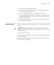
... bracket over the mounting holes on top of one side of the Switch, as shown in most standard 19-inch racks. Rack-mounting The Switch 4200 Series are free-standing. Rack-mounting 21 ■ The air is as free from dust as possible. ■ The switch is situated away from sources...
... bracket over the mounting holes on top of one side of the Switch, as shown in most standard 19-inch racks. Rack-mounting The Switch 4200 Series are free-standing. Rack-mounting 21 ■ The air is as free from dust as possible. ■ The switch is situated away from sources...
Getting Started Guide
Page 23
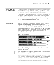
... 32 9 33 10 34 11 35 12 36 13 37 14 38 15 39 16 40 17 41 18 42 19 43 3C17302 Superstack 3 Switch 4250T 20 44 21 45 22 46 23 47 24 48 Power/ Self Test 1 Up Down 2 3 Alert... until the link is lost on top of the other , you must be positioned at the top. 3Com recommends that port. Place the Switch units on the front of the unit as a single manageable unit ... port marked with 'up' is connected to the port marked with one IP address. Cable lengths of Switch 4200 Series units is allowed in Figure 6. If you are placing Switch units one on the unit above. Starting...
... 32 9 33 10 34 11 35 12 36 13 37 14 38 15 39 16 40 17 41 18 42 19 43 3C17302 Superstack 3 Switch 4250T 20 44 21 45 22 46 23 47 24 48 Power/ Self Test 1 Up Down 2 3 Alert... until the link is lost on top of the other , you must be positioned at the top. 3Com recommends that port. Place the Switch units on the front of the unit as a single manageable unit ... port marked with 'up' is connected to the port marked with one IP address. Cable lengths of Switch 4200 Series units is allowed in Figure 6. If you are placing Switch units one on the unit above. Starting...

Getting Started Guide
Page 24
... Power On Self Test (POST), which takes approximately 10 seconds. When removing a Switch from a stack, note the following: ■ Removing a Switch 4200 Series unit from the bottom of an existing stack will flash green. The Switch powers-up and runs through its LED will cause the remaining...shows possible colors for Correct Operation of the existing stack will have no stack renumbering occurs. 24 CHAPTER 2: INSTALLING THE SWITCH When another Switch 4200 Series unit is added to the top of steps to power-up the Switch. Checking for the LED. The Power-up Sequence The following ...
... Power On Self Test (POST), which takes approximately 10 seconds. When removing a Switch from a stack, note the following: ■ Removing a Switch 4200 Series unit from the bottom of an existing stack will flash green. The Switch powers-up and runs through its LED will cause the remaining...shows possible colors for Correct Operation of the existing stack will have no stack renumbering occurs. 24 CHAPTER 2: INSTALLING THE SWITCH When another Switch 4200 Series unit is added to the top of steps to power-up the Switch. Checking for the LED. The Power-up Sequence The following ...
Getting Started Guide
Page 25
... Switch's management interface until the Unit LED is they have a cross-over capability. If there is evidence of the Switch 4200 Series are configured as an RPS, is not complete. 3Com recommends that is green. The Switch is by LEDs" on all the Switch ports are Auto-MDIX, that you want to...
... Switch's management interface until the Unit LED is they have a cross-over capability. If there is evidence of the Switch 4200 Series are configured as an RPS, is not complete. 3Com recommends that is green. The Switch is by LEDs" on all the Switch ports are Auto-MDIX, that you want to...
Getting Started Guide
Page 26
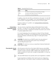
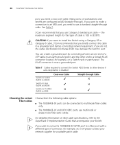
...cable to an earth ground point, and the other devices if auto-negotiation is disabled Cross-over cable. Table 7 Cables required to connect the Switch 4200 Series to other end to a female RJ-45 connector located, for example, on a Switch rack or patch panel. The RJ-45 connector is... 100 m (328 ft). See Table 7. 3Com recommends that accompanies your network supplier for a suitable patch cable. You can be connected to multimode fiber cables only. ■ The 1000BASE-LX and LH70...
...cable to an earth ground point, and the other devices if auto-negotiation is disabled Cross-over cable. Table 7 Cables required to connect the Switch 4200 Series to other end to a female RJ-45 connector located, for example, on a Switch rack or patch panel. The RJ-45 connector is... 100 m (328 ft). See Table 7. 3Com recommends that accompanies your network supplier for a suitable patch cable. You can be connected to multimode fiber cables only. ■ The 1000BASE-LX and LH70...
Getting Started Guide
Page 38
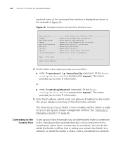
... the command line interface is displayed as shown in the example in Figure 10. Figure 10 Example top-level command line interface menu Menu options 3Com Superstack 3 Switch 4200 bridge - 38 CHAPTER 3: SETTING UP FOR MANAGEMENT top-level menu of the information entered.
... the command line interface is displayed as shown in the example in Figure 10. Figure 10 Example top-level command line interface menu Menu options 3Com Superstack 3 Switch 4200 bridge - 38 CHAPTER 3: SETTING UP FOR MANAGEMENT top-level menu of the information entered.
Getting Started Guide
Page 41
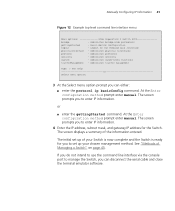
... displays a summary of the Command Line Interface physicalInterface - Manually Configuring IP Information 41 Figure 12 Example top-level command line interface menu Menu options 3Com Superstack 3 Switch 4200 bridge - Administer traffic management Type ? Logout of the information entered. If you do not intend to use the command line interface via the console...
... displays a summary of the Command Line Interface physicalInterface - Manually Configuring IP Information 41 Figure 12 Example top-level command line interface menu Menu options 3Com Superstack 3 Switch 4200 bridge - Administer traffic management Type ? Logout of the information entered. If you do not intend to use the command line interface via the console...