User Guide
Page 3
...BASELINE SWITCH Overview of the Baseline Switch 2226-PWR Plus 7 Features and Capabilities 7 Autosensing of MDI/MDIX Connections 7 Autonegotiating 10/100 Mbps Ports 7 Power over Ethernet (PoE) 8 SFP Ports 8 Traffic Prioritization 8 Physical Features 9 Front Panel 9 Rear Panel 12 Package Contents 13 2 INSTALLING THE SWITCH Before You Begin 15 Positioning the Switch...Using Discovery 26 DHCP Assigned IP Address 27 Manually Assigned (Static) IP Address 27 4 CONFIGURING THE SWITCH Configuration Overview 29 Viewing Status Information 29 Changing the Admin Password 30 Modifying the IP Address Settings ...
...BASELINE SWITCH Overview of the Baseline Switch 2226-PWR Plus 7 Features and Capabilities 7 Autosensing of MDI/MDIX Connections 7 Autonegotiating 10/100 Mbps Ports 7 Power over Ethernet (PoE) 8 SFP Ports 8 Traffic Prioritization 8 Physical Features 9 Front Panel 9 Rear Panel 12 Package Contents 13 2 INSTALLING THE SWITCH Before You Begin 15 Positioning the Switch...Using Discovery 26 DHCP Assigned IP Address 27 Manually Assigned (Static) IP Address 27 4 CONFIGURING THE SWITCH Configuration Overview 29 Viewing Status Information 29 Changing the Admin Password 30 Modifying the IP Address Settings ...
User Guide
Page 6
...9632; Document title ■ Document part number (on the title page) ■ Page number (if appropriate) Example: ■ 3Com Baseline Switch 2226-PWR Plus User Guide ■ Part number: DUA1649-0AAA02 ■ Page 25 Please note that helps you . 6 ABOUT THIS GUIDE Related... Documentation In addition to this guide, each 3Com Baseline Switch 2226-PWR Plus documentation set includes the following information when contacting us . Provide information about the current software release, including new features, ...
...9632; Document title ■ Document part number (on the title page) ■ Page number (if appropriate) Example: ■ 3Com Baseline Switch 2226-PWR Plus User Guide ■ Part number: DUA1649-0AAA02 ■ Page 25 Please note that helps you . 6 ABOUT THIS GUIDE Related... Documentation In addition to this guide, each 3Com Baseline Switch 2226-PWR Plus documentation set includes the following information when contacting us . Provide information about the current software release, including new features, ...
User Guide
Page 7
... crossover (MDIX) connections. Autonegotiating 10/100 Mbps Ports Each 10/100 Mbps port automatically determines the speed and duplex mode of the 3Com® Baseline Switch 2226-PWR Plus. Overview of the Baseline Switch 2226-PWR Plus The 3Com Baseline Switch 2226-PWR Plus is necessary, unless you to connect network devices to fiber-based Gigabit media. This allows you want the high-speed performance of 10...
... crossover (MDIX) connections. Autonegotiating 10/100 Mbps Ports Each 10/100 Mbps port automatically determines the speed and duplex mode of the 3Com® Baseline Switch 2226-PWR Plus. Overview of the Baseline Switch 2226-PWR Plus The 3Com Baseline Switch 2226-PWR Plus is necessary, unless you to connect network devices to fiber-based Gigabit media. This allows you want the high-speed performance of 10...
User Guide
Page 8
...that traffic. If a packet is forwarded through port. The Switch is connected to any combination. This ensures that it is given the highest priority. 8 CHAPTER 1: INTRODUCING THE BASELINE SWITCH Power over Ethernet (PoE) The Switch supports Power over Ethernet (PoE) on all 24 ports. If... you the flexibility of IP Phone Traffic The Switch can also configure the PoE settings for your network connection...
...that traffic. If a packet is forwarded through port. The Switch is connected to any combination. This ensures that it is given the highest priority. 8 CHAPTER 1: INTRODUCING THE BASELINE SWITCH Power over Ethernet (PoE) The Switch supports Power over Ethernet (PoE) on all 24 ports. If... you the flexibility of IP Phone Traffic The Switch can also configure the PoE settings for your network connection...

User Guide
Page 9
...1 Front and Rear Panels 1 2 3 4 9 5 10 67 8 Front Panel The front panel of the Switch contains a series of indicator lights (LEDs) that help describe the state of the Switch. Table 3 Priority Levels for Traffic Types Priority Level Traffic Type 0 Best effort 1 Background 2 Standard (spare) ...interactive voice), less than 10 milliseconds latency and jitter 7 Network control reserved traffic The traffic prioritization feature supported by the Switch is being delivered No power is compatible with the relevant sections of traffic. ing power. The priority levels and their ...
...1 Front and Rear Panels 1 2 3 4 9 5 10 67 8 Front Panel The front panel of the Switch contains a series of indicator lights (LEDs) that help describe the state of the Switch. Table 3 Priority Levels for Traffic Types Priority Level Traffic Type 0 Best effort 1 Background 2 Standard (spare) ...interactive voice), less than 10 milliseconds latency and jitter 7 Network control reserved traffic The traffic prioritization feature supported by the Switch is being delivered No power is compatible with the relevant sections of traffic. ing power. The priority levels and their ...
User Guide
Page 10
...252;rfen an diese Datensteckdosen angeschlossen werden. ADVERTENCIA: Puertos RJ-45. The Switch has 24 10/100 Mbps autonegotiating ports. their speed and duplex mode ...front panel ports in conformance to the 802.3af specification. The Switch will automatically detect PoE devices connected to these data sockets. Nur...detection and can be used to deliver Power over Ethernet. The Switch will supply up to 15.4W of power through any of ... cavi dati schermati o non schermati con connettori schermati o non schermati. The Switch incorporates an LED Ports 1 to 24 can be connected to these ports and...
...252;rfen an diese Datensteckdosen angeschlossen werden. ADVERTENCIA: Puertos RJ-45. The Switch has 24 10/100 Mbps autonegotiating ports. their speed and duplex mode ...front panel ports in conformance to the 802.3af specification. The Switch will automatically detect PoE devices connected to these data sockets. Nur...detection and can be used to deliver Power over Ethernet. The Switch will supply up to 15.4W of power through any of ... cavi dati schermati o non schermati con connettori schermati o non schermati. The Switch incorporates an LED Ports 1 to 24 can be connected to these ports and...

User Guide
Page 11
... Verify that the attached device is powered on ■ Verify that autonegotiation is enabled, if it may notice some degradation of network performance. 3Com recommends that you use devices that are capable of any SFP modules that you can use straight-through or crossover cables for further advice. ... LEDs show the link status of ports and the speed of connected devices. If the connected device does not support autonegotiation, the Switch will operate in the slot (4) Link/Activity LEDs The Link/Activity LEDs show the status of autonegotiation (and that are combination Gigabit...
... Verify that the attached device is powered on ■ Verify that autonegotiation is enabled, if it may notice some degradation of network performance. 3Com recommends that you use devices that are capable of any SFP modules that you can use straight-through or crossover cables for further advice. ... LEDs show the link status of ports and the speed of connected devices. If the connected device does not support autonegotiation, the Switch will operate in the slot (4) Link/Activity LEDs The Link/Activity LEDs show the status of autonegotiation (and that are combination Gigabit...
User Guide
Page 12
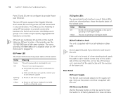
...receiving power: ■ Verify that the pads locate with four self-adhesive rubber pads. rectly ■ If the unit still does not operate, contact your 3Com network supplier ■ Power-on self-test is in fail-safe mode. (7) Duplex LEDs The second and fourth (bottom) row of Status LEDs, which ... cord is supplied with the recesses of the lower unit. Place the unit on self-test or loopback test failed. 12 CHAPTER 1: INTRODUCING THE BASELINE SWITCH Ports 25 and 26 are not configured to provide Power over the 10/100/1000 port of the same number. Status Off Yellow Meaning No...
...receiving power: ■ Verify that the pads locate with four self-adhesive rubber pads. rectly ■ If the unit still does not operate, contact your 3Com network supplier ■ Power-on self-test is in fail-safe mode. (7) Duplex LEDs The second and fourth (bottom) row of Status LEDs, which ... cord is supplied with the recesses of the lower unit. Place the unit on self-test or loopback test failed. 12 CHAPTER 1: INTRODUCING THE BASELINE SWITCH Ports 25 and 26 are not configured to provide Power over the 10/100/1000 port of the same number. Status Off Yellow Meaning No...
User Guide
Page 13
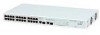
Package Contents The 3Com Baseline Switch 2226-PWR Plus package includes the following items: ■ One 3Com Baseline Switch 2226-PWR Plus unit ■ One power cord ■ Four standard height, self-adhesive rubber pads ■ One mounting kit ■ One CD-ROM, which contains this User Guide, the 3Com Discovery application, and the 3Com TFTP Server ■ One warranty flyer Before installing and using...
Package Contents The 3Com Baseline Switch 2226-PWR Plus package includes the following items: ■ One 3Com Baseline Switch 2226-PWR Plus unit ■ One power cord ■ Four standard height, self-adhesive rubber pads ■ One mounting kit ■ One CD-ROM, which contains this User Guide, the 3Com Discovery application, and the 3Com TFTP Server ■ One warranty flyer Before installing and using...

User Guide
Page 14
14 CHAPTER 1: INTRODUCING THE BASELINE SWITCH
14 CHAPTER 1: INTRODUCING THE BASELINE SWITCH

User Guide
Page 15
...where it can be free-standing or mounted in Appendix B of this guide. When deciding where to position the Switch, ensure that you need to the Switch ■ Connecting a Network Device ■ Connecting a Network Device ■ Performing Spot Checks Before You Begin... di manutenzione, leggere le informazioni di sicurezza riportate nell'Appendice B (Appendix B) della presente guida per l'utente. 2 INSTALLING THE SWITCH This chapter contains information that : ADVERTENCIA: Información de Seguridad. AVERTISSEMENT: Consignes de Sécurité. Before installing or removing...
...where it can be free-standing or mounted in Appendix B of this guide. When deciding where to position the Switch, ensure that you need to the Switch ■ Connecting a Network Device ■ Connecting a Network Device ■ Performing Spot Checks Before You Begin... di manutenzione, leggere le informazioni di sicurezza riportate nell'Appendice B (Appendix B) della presente guida per l'utente. 2 INSTALLING THE SWITCH This chapter contains information that : ADVERTENCIA: Información de Seguridad. AVERTISSEMENT: Consignes de Sécurité. Before installing or removing...

User Guide
Page 16
...case is not restricted (3Com recommends that the unit be free-standing. Static discharge can interfere with the front facing towards you provide a minimum of electrical noise. The Switch is supplied with a suitable screwdriver. If one side of different size Baseline or SuperStack® 3... units, the smaller units must be exceeded. CAUTION: If installing the Switch in a free-standing stack of the unit. 3...
...case is not restricted (3Com recommends that the unit be free-standing. Static discharge can interfere with the front facing towards you provide a minimum of electrical noise. The Switch is supplied with a suitable screwdriver. If one side of different size Baseline or SuperStack® 3... units, the smaller units must be exceeded. CAUTION: If installing the Switch in a free-standing stack of the unit. 3...

User Guide
Page 17
...earth ground during normal use the self-adhesive rubber pads supplied. If you are mixing a variety of Baseline and SuperStack units, the smaller units must use . Supplying Power to the Switch Power problems can be placed one on top of the other, you must be positioned at each other... Before powering on top of each corner. Installing proper grounding helps to avoid damage from sags and surges to avoid unforeseen network outages. 3Com recommends that the pads of the upper unit line up to four units can be grounded. If you install power conditioning, especially in ...
...earth ground during normal use the self-adhesive rubber pads supplied. If you are mixing a variety of Baseline and SuperStack units, the smaller units must use . Supplying Power to the Switch Power problems can be placed one on top of the other, you must be positioned at each other... Before powering on top of each corner. Installing proper grounding helps to avoid damage from sags and surges to avoid unforeseen network outages. 3Com recommends that the pads of the upper unit line up to four units can be grounded. If you install power conditioning, especially in ...

User Guide
Page 18
... Defaults" on the front panel of the Switch flashes green. CAUTION: Resetting the Switch to reconfigure the Switch after you power on page 12 for a solution. To visit the 3Com Knowledgebase Web site, start your Web browser, and then enter http://knowledgebase.3com.com. ■ Contact your settings. For...The unit is connected correctly, and then try powering on the Switch again ■ If the Switch still does not operate, contact your 3Com network supplier If POST fails, try the following: ■ Power off the Switch, and then power it means that the power cord is ...
... Defaults" on the front panel of the Switch flashes green. CAUTION: Resetting the Switch to reconfigure the Switch after you power on page 12 for a solution. To visit the 3Com Knowledgebase Web site, start your Web browser, and then enter http://knowledgebase.3com.com. ■ Contact your settings. For...The unit is connected correctly, and then try powering on the Switch again ■ If the Switch still does not operate, contact your 3Com network supplier If POST fails, try the following: ■ Power off the Switch, and then power it means that the power cord is ...
User Guide
Page 19
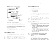
... 3CSFP91 SFP (SX) ■ 3CSFP92 SFP (LX) To access the latest list of approved SFP transceivers for the Switch on the 3Com Corporation World Wide Web site, enter this URL into any SFP port without having to insert and remove an SFP transceiver...using Category 5e or 6 cables. Using SFP Transceivers 19 Figure 3 Connecting Devices to the Switch Baseline 10/100 switch Endstations on switched 100 Mbps connections Baseline 10/100 switch Endstations on switched 100 Mbps connections Baseline Switch 2226-PWR Plus 1 42753*8609 # 1 42753*8609 # PoE-compliant devices 1000 Mbps link 10 or ...
... 3CSFP91 SFP (SX) ■ 3CSFP92 SFP (LX) To access the latest list of approved SFP transceivers for the Switch on the 3Com Corporation World Wide Web site, enter this URL into any SFP port without having to insert and remove an SFP transceiver...using Category 5e or 6 cables. Using SFP Transceivers 19 Figure 3 Connecting Devices to the Switch Baseline 10/100 switch Endstations on switched 100 Mbps connections Baseline 10/100 switch Endstations on switched 100 Mbps connections Baseline Switch 2226-PWR Plus 1 42753*8609 # 1 42753*8609 # PoE-compliant devices 1000 Mbps link 10 or ...

User Guide
Page 20
...properly inserted only one way. Removing an SFP Transceiver Removing an SFP transceiver does not require powering off the Switch. Regular checks can be least effect on host Switch 2 Gently slide the transceiver into the SFP slot until it is closed (in Figure 4. 20 CHAPTER ... Ensure the wire release lever is operating correctly. The SFP transceiver should visually check the Switch. Figure 4 Inserting the SFP Transceiver Product label Wire release lever Suitable slot on users. 3Com recommends periodically checking the items listed in Table 5. To remove an SFP transceiver: 1 ...
...properly inserted only one way. Removing an SFP Transceiver Removing an SFP transceiver does not require powering off the Switch. Regular checks can be least effect on host Switch 2 Gently slide the transceiver into the SFP slot until it is closed (in Figure 4. 20 CHAPTER ... Ensure the wire release lever is operating correctly. The SFP transceiver should visually check the Switch. Figure 4 Inserting the SFP Transceiver Product label Wire release lever Suitable slot on users. 3Com recommends periodically checking the items listed in Table 5. To remove an SFP transceiver: 1 ...

User Guide
Page 21
Performing Spot Checks 21 The fan is operating by listening to the unit. Table 5 Items to Check Item Verify That Cabling All external cabling connections are secure and that no cables are pulled taut Cooling fan Where possible, check that the cooling fan is fitted on page 51. If you experience any problems operating the Switch, refer to "Troubleshooting" starting on the right side of the unit (when viewed from the front).
Performing Spot Checks 21 The fan is operating by listening to the unit. Table 5 Items to Check Item Verify That Cabling All external cabling connections are secure and that no cables are pulled taut Cooling fan Where possible, check that the cooling fan is fitted on page 51. If you experience any problems operating the Switch, refer to "Troubleshooting" starting on the right side of the unit (when viewed from the front).

User Guide
Page 22
22 CHAPTER 2: INSTALLING THE SWITCH
22 CHAPTER 2: INSTALLING THE SWITCH
User Guide
Page 23
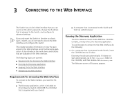
... discovery.exe. If you only want the Switch to function as a basic layer 2 switch, you need to access the Web interface and configure the Switch. This chapter provides information on 3Com Baseline Switch 2226-PWR Plus CD-ROM that is supplied with your Switch ■ A computer that is connected to... of Discovery appears. It also introduces the menu items and buttons that has a Web browser Running the Discovery Application The 3Com Baseline Switch 2226-PWR Plus CD-ROM contains, among others, the Discovery application. To use to set the admin password, change the IP address that...
... discovery.exe. If you only want the Switch to function as a basic layer 2 switch, you need to access the Web interface and configure the Switch. This chapter provides information on 3Com Baseline Switch 2226-PWR Plus CD-ROM that is supplied with your Switch ■ A computer that is connected to... of Discovery appears. It also introduces the menu items and buttons that has a Web browser Running the Discovery Application The 3Com Baseline Switch 2226-PWR Plus CD-ROM contains, among others, the Discovery application. To use to set the admin password, change the IP address that...
User Guide
Page 24
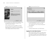
... Application screen appears. 4 Click Finish. If the computer has only one adapter, click Next. Discovery searches the network for 3Com devices. Logging On to the Web Interface After the Web interface loads in your Web browser, the first page that connects the computer ... network adapters, select the adapter that appears is complete, the Discovered Devices screen displays detected network devices. 3 On the Discovered Devices screen, click Baseline Switch 2226-PWR Plus, and then click Next. On this screen, you need to enter the administration user name and password to gain access to the...
... Application screen appears. 4 Click Finish. If the computer has only one adapter, click Next. Discovery searches the network for 3Com devices. Logging On to the Web Interface After the Web interface loads in your Web browser, the first page that connects the computer ... network adapters, select the adapter that appears is complete, the Discovered Devices screen displays detected network devices. 3 On the Discovered Devices screen, click Baseline Switch 2226-PWR Plus, and then click Next. On this screen, you need to enter the administration user name and password to gain access to the...


