
Owners Manual
Page 6
... up a cold engine ...6-1 Starting a warm engine ...6-2 Shifting ...6-2 Engine break-in ...6-4 Parking ...6-5 PERIODIC MAINTENANCE AND ADJUSTMENT ...7-1 Owner's tool kit ...7-2 Periodic maintenance chart for the emission control system ...7-3 General maintenance and lubrication chart ...7-4 Removing and installing panels ...7-8 Checking the spark plugs ...7-9 Canister (for California only) ...7-10 Engine oil and oil filter element ...7-11 Final gear oil ...7-13 Cleaning the air filter element ...7-14 Carburetors ...7-16 Checking the engine idling speed ...7-16 Checking the throttle cable free...
... up a cold engine ...6-1 Starting a warm engine ...6-2 Shifting ...6-2 Engine break-in ...6-4 Parking ...6-5 PERIODIC MAINTENANCE AND ADJUSTMENT ...7-1 Owner's tool kit ...7-2 Periodic maintenance chart for the emission control system ...7-3 General maintenance and lubrication chart ...7-4 Removing and installing panels ...7-8 Checking the spark plugs ...7-9 Canister (for California only) ...7-10 Engine oil and oil filter element ...7-11 Final gear oil ...7-13 Cleaning the air filter element ...7-14 Carburetors ...7-16 Checking the engine idling speed ...7-16 Checking the throttle cable free...
Owners Manual
Page 7
... the steering ...7-29 Checking the wheel bearings ...7-30 Battery ...7-30 Replacing the fuses ...7-31 Replacing the headlight bulb ...7-32 Replacing a turn signal light bulb or the tail/brake light bulb ...7-34 Supporting the motorcycle ...7-34 Front wheel ...7-35 Rear wheel ...7-36 Troubleshooting ...7-38 Troubleshooting chart ...7-39 MOTORCYCLE CARE AND STORAGE ...8-1 Matte color caution ...8-1 Care ...8-1 Storage ...8-3 SPECIFICATIONS ...9-1 CONSUMER INFORMATION...10-1 Identification numbers ...10-1 Reporting safety defects ...10-3 Motorcycle noise regulation ...10-4 Maintenance record...
... the steering ...7-29 Checking the wheel bearings ...7-30 Battery ...7-30 Replacing the fuses ...7-31 Replacing the headlight bulb ...7-32 Replacing a turn signal light bulb or the tail/brake light bulb ...7-34 Supporting the motorcycle ...7-34 Front wheel ...7-35 Rear wheel ...7-36 Troubleshooting ...7-38 Troubleshooting chart ...7-39 MOTORCYCLE CARE AND STORAGE ...8-1 Matte color caution ...8-1 Care ...8-1 Storage ...8-3 SPECIFICATIONS ...9-1 CONSUMER INFORMATION...10-1 Identification numbers ...10-1 Reporting safety defects ...10-3 Motorcycle noise regulation ...10-4 Maintenance record...
Owners Manual
Page 13
G Shifting weights can create unstable handling or a slow steering response. Make sure that has added cargo or accessories. Check accessory mounts and cargo restraints frequently. • Properly adjust the suspension for your load (suspension-adjustable models only), and check the condition and pressure of your vehicle. 2-3 ... vehicle is not designed to pull a trailer or to be attached to a sidecar. 2 Genuine Yamaha Accessories Choosing accessories for use extreme caution when adding cargo or accessories to your motorcycle: The total weight of the operator, passenger, accessories ...
G Shifting weights can create unstable handling or a slow steering response. Make sure that has added cargo or accessories. Check accessory mounts and cargo restraints frequently. • Properly adjust the suspension for your load (suspension-adjustable models only), and check the condition and pressure of your vehicle. 2-3 ... vehicle is not designed to pull a trailer or to be attached to a sidecar. 2 Genuine Yamaha Accessories Choosing accessories for use extreme caution when adding cargo or accessories to your motorcycle: The total weight of the operator, passenger, accessories ...
Owners Manual
Page 14
... your tires. If electrical accessories exceed the capacity of the motorcycle's electrical system, an electric failure could result, which could cause a dangerous loss of the operator and may become unstable in design and quality to genuine Yamaha accessories, recognize that change any way reduce ground clearance or cornering clearance, limit suspension travel, steering travel or control operation, or obscure lights or reflectors. • Accessories fitted...
... your tires. If electrical accessories exceed the capacity of the motorcycle's electrical system, an electric failure could result, which could cause a dangerous loss of the operator and may become unstable in design and quality to genuine Yamaha accessories, recognize that change any way reduce ground clearance or cornering clearance, limit suspension travel, steering travel or control operation, or obscure lights or reflectors. • Accessories fitted...
Owners Manual
Page 21
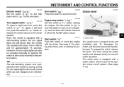
... switch to crank the engine with a clutch switch, which is part of an emergency, such as when the vehicle overturns or when the throttle cable is stuck. 4 EAU12711 Start switch " " Push this model is equipped with the starter. The lever should be canceled manually by pushing the switch in case of the ignition circuit cut-off system. (See page 4-16.) 4-4 Engine stop switch " / " Set this switch...
... switch to crank the engine with a clutch switch, which is part of an emergency, such as when the vehicle overturns or when the throttle cable is stuck. 4 EAU12711 Start switch " " Push this model is equipped with the starter. The lever should be canceled manually by pushing the switch in case of the ignition circuit cut-off system. (See page 4-16.) 4-4 Engine stop switch " / " Set this switch...

Owners Manual
Page 24
.... If gasoline spills on the vehicle. Your Yamaha engine has been designed to spill out of water heaters and clothes dryers. 2. Handle gasoline with soap and water. To avoid fires and explosions and to internal engine parts, such as the valves and piston rings, as well as the pilot lights of the fuel tank. 4 1. Before refueling, turn off spilled fuel with a pump octane number [(R+M)/2] of 86...
.... If gasoline spills on the vehicle. Your Yamaha engine has been designed to spill out of water heaters and clothes dryers. 2. Handle gasoline with soap and water. To avoid fires and explosions and to internal engine parts, such as the valves and piston rings, as well as the pilot lights of the fuel tank. 4 1. Before refueling, turn off spilled fuel with a pump octane number [(R+M)/2] of 86...
Owners Manual
Page 31
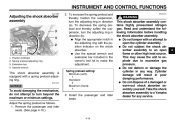
... the shock absorber. Spring preload setting: Minimum (soft): 1 Standard: 3 Maximum (hard): 7 EWA10221 WARNING This shock absorber assembly contains highly pressurized nitrogen gas. Take the shock absorber assembly to an open the cylinder assembly. Adjust the spring preload as follows. 1. INSTRUMENT AND CONTROL FUNCTIONS EAU14863 Adjusting the shock absorber assembly 1. 2. 3. 4. G Align the appropriate notch in poor damping performance. This may cause the unit to explode due to turn beyond...
... the shock absorber. Spring preload setting: Minimum (soft): 1 Standard: 3 Maximum (hard): 7 EWA10221 WARNING This shock absorber assembly contains highly pressurized nitrogen gas. Take the shock absorber assembly to an open the cylinder assembly. Adjust the spring preload as follows. 1. INSTRUMENT AND CONTROL FUNCTIONS EAU14863 Adjusting the shock absorber assembly 1. 2. 3. 4. G Align the appropriate notch in poor damping performance. This may cause the unit to explode due to turn beyond...
Owners Manual
Page 35
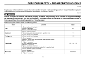
... vehicle, check the following points: ITEM Fuel • Check fuel level in fuel tank. • Refuel if necessary. • Check fuel line for leakage. • Check oil level in engine. • If necessary, add recommended oil to make sure the vehicle is in safe operating condition. Check fluid level in the Owner's Manual. Before using this manual, have Yamaha dealer bleed hydraulic system. Check brake pads for wear. Replace...
... vehicle, check the following points: ITEM Fuel • Check fuel level in fuel tank. • Refuel if necessary. • Check fuel line for leakage. • Check oil level in engine. • If necessary, add recommended oil to make sure the vehicle is in safe operating condition. Check fluid level in the Owner's Manual. Before using this manual, have Yamaha dealer bleed hydraulic system. Check brake pads for wear. Replace...
Owners Manual
Page 37
... and completely close the throttle. (See page 4-10.) 5. When the engine is cold! [ECA11041] 7. Turn the fuel cock lever to check the electrical circuit. 4. Turn the key to "ON" and make sure that the engine stop switch is a control or function you do not understand, ask your Yamaha dealer. OPERATION AND IMPORTANT RIDING POINTS EAU15951 EAU15997 Read the Owner's Manual carefully to become familiar...
... and completely close the throttle. (See page 4-10.) 5. When the engine is cold! [ECA11041] 7. Turn the fuel cock lever to check the electrical circuit. 4. Turn the key to "ON" and make sure that the engine stop switch is a control or function you do not understand, ask your Yamaha dealer. OPERATION AND IMPORTANT RIDING POINTS EAU15951 EAU15997 Read the Owner's Manual carefully to become familiar...

Owners Manual
Page 39
... or runs very roughly, pull the clutch lever in the neutral position, do not coast for long distances. EAU16700 NOTICE G G Even with the engine off , accelerating, climbing hills, etc. OPERATION AND IMPORTANT RIDING POINTS Shifting gears lets you control the amount of engine power available for starting off , and do not tow the motorcycle for long periods of time with the transmission...
... or runs very roughly, pull the clutch lever in the neutral position, do not coast for long distances. EAU16700 NOTICE G G Even with the engine off , accelerating, climbing hills, etc. OPERATION AND IMPORTANT RIDING POINTS Shifting gears lets you control the amount of engine power available for starting off , and do not tow the motorcycle for long periods of time with the transmission...
Owners Manual
Page 44
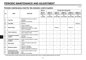
Replace. 4 * Valve clearance Crankcase breather system Carburetor synchronization Idle speed 7 5 * 6 * 7 * 8 * Exhaust system Evaporative emission control system (for the emission control system INITIAL No. PERIODIC MAINTENANCE AND ADJUSTMENT EAU17600 Periodic maintenance chart for California only) 9 * √ √ * Since these items require special tools, data and technical skills, have a Yamaha dealer perform the service. 7-3 ITEM ROUTINE 600 mi (1000 km) or 1 month 4000 mi (7000...
Replace. 4 * Valve clearance Crankcase breather system Carburetor synchronization Idle speed 7 5 * 6 * 7 * 8 * Exhaust system Evaporative emission control system (for the emission control system INITIAL No. PERIODIC MAINTENANCE AND ADJUSTMENT EAU17600 Periodic maintenance chart for California only) 9 * √ √ * Since these items require special tools, data and technical skills, have a Yamaha dealer perform the service. 7-3 ITEM ROUTINE 600 mi (1000 km) or 1 month 4000 mi (7000...
Owners Manual
Page 73
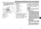
..., have a Yamaha dealer check the electrical system. 7 7-32 Headlight fuse Signaling system fuse Ignition fuse Carburetor heater fuse Ignitor unit fuse Spare fuse 3. ECA10650 NOTICE Take care not to damage the following parts: G Headlight bulb Do not touch the glass part of the headlight bulb to the electrical system and possibly a fire. [EWA15131] EAU23795 Specified fuses: Main fuse: 30.0 A Signaling system fuse: 10.0 A Ignition fuse: 10.0 A Headlight fuse: 15.0 A Carburetor heater fuse: 15.0 A Ignitor unit fuse: 5.0 A Replacing the headlight bulb This model is...
..., have a Yamaha dealer check the electrical system. 7 7-32 Headlight fuse Signaling system fuse Ignition fuse Carburetor heater fuse Ignitor unit fuse Spare fuse 3. ECA10650 NOTICE Take care not to damage the following parts: G Headlight bulb Do not touch the glass part of the headlight bulb to the electrical system and possibly a fire. [EWA15131] EAU23795 Specified fuses: Main fuse: 30.0 A Signaling system fuse: 10.0 A Ignition fuse: 10.0 A Headlight fuse: 15.0 A Carburetor heater fuse: 15.0 A Ignitor unit fuse: 5.0 A Replacing the headlight bulb This model is...
Owners Manual
Page 78
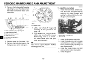
... assembly: wheel, wheel axle, final gear case, and drive shaft. Remove the brake pedal free play adjusting nut, and then disconnect the brake rod from the brake camshaft lever. Bolt 2. Remove panel A. (See page 7-8.) 6. Install the final gear case bolts. 3. PERIODIC MAINTENANCE AND ADJUSTMENT 4. Middle gear universal joint 2. Drive shaft 2. Install the rear wheel, wheel axle, final gear case, and drive shaft by pushing the wheel forward and guiding the drive shaft into the middle gear universal joint...
... assembly: wheel, wheel axle, final gear case, and drive shaft. Remove the brake pedal free play adjusting nut, and then disconnect the brake rod from the brake camshaft lever. Bolt 2. Remove panel A. (See page 7-8.) 6. Install the final gear case bolts. 3. PERIODIC MAINTENANCE AND ADJUSTMENT 4. Middle gear universal joint 2. Drive shaft 2. Install the rear wheel, wheel axle, final gear case, and drive shaft by pushing the wheel forward and guiding the drive shaft into the middle gear universal joint...
Owners Manual
Page 79
...-how to expensive repair bills. PERIODIC MAINTENANCE AND ADJUSTMENT 6. However, should your motorcycle require any repair, take it is on the ground, and then put the sidestand down. 7. EWA15141 heaters or furnaces. Tighten the axle nut, the final gear case bolts and the brake torque rod nuts to a Yamaha dealer, whose skilled technicians have a shorter service life and can ignite or explode...
...-how to expensive repair bills. PERIODIC MAINTENANCE AND ADJUSTMENT 6. However, should your motorcycle require any repair, take it is on the ground, and then put the sidestand down. 7. EWA15141 heaters or furnaces. Tighten the axle nut, the final gear case bolts and the brake torque rod nuts to a Yamaha dealer, whose skilled technicians have a shorter service life and can ignite or explode...
Owners Manual
Page 84
... tire air pressure, and then lift the motorcycle so that the electrodes are off the ground. Remove the spark plug caps and spark plugs. b. To prevent damage or injury from deteriorating. 5. e. Lubricate all control cables and the pivoting points of all levers and pedals as well as of its wheels are grounded. (This will prevent fuel deposits from corrosion. Cover the muffler outlets with oil.) WARNING! Remove the battery...
... tire air pressure, and then lift the motorcycle so that the electrodes are off the ground. Remove the spark plug caps and spark plugs. b. To prevent damage or injury from deteriorating. 5. e. Lubricate all control cables and the pivoting points of all levers and pedals as well as of its wheels are grounded. (This will prevent fuel deposits from corrosion. Cover the muffler outlets with oil.) WARNING! Remove the battery...
Owners Manual
Page 85
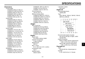
... (518 lb) Engine: Engine type: Air cooled 4-stroke, SOHC Cylinder arrangement: V-type 2-cylinder Displacement: 649 cm³ Bore × stroke: 81.0 × 63.0 mm (3.19 × 2.48 in) Compression ratio: 9.00 :1 Starting system: Electric starter Recommended engine oil grade: API service SG type or higher, JASO standard MA Engine oil quantity: Without oil filter element replacement: 2.60 L (2.75 US qt, 2.29 Imp.qt) With oil filter element replacement: 2.80 L (2.96...
... (518 lb) Engine: Engine type: Air cooled 4-stroke, SOHC Cylinder arrangement: V-type 2-cylinder Displacement: 649 cm³ Bore × stroke: 81.0 × 63.0 mm (3.19 × 2.48 in) Compression ratio: 9.00 :1 Starting system: Electric starter Recommended engine oil grade: API service SG type or higher, JASO standard MA Engine oil quantity: Without oil filter element replacement: 2.60 L (2.75 US qt, 2.29 Imp.qt) With oil filter element replacement: 2.80 L (2.96...
Owners Manual
Page 88
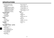
...W × 1 Engine trouble warning light: 12 V, 1.7 W × 1 Fuses: Main fuse: 30.0 A Headlight fuse: 15.0 A Signaling system fuse: 10.0 A Ignition fuse: 10.0 A Carburetor heater fuse: 15.0 A Ignitor unit fuse: 5.0 A Electrical system: Ignition system: TCI (digital) Charging system: AC magneto Battery: Model: GT12B-4 Voltage, capacity: 12 V, 10.0 Ah Headlight: Bulb type: Halogen bulb Bulb voltage, wattage × quantity: Headlight: 12 V, 60 W/55 W × 1 Tail/brake light: 12 V, 8.0 W/27.0 W × 1 Front turn signal/position light: 12 V, 23 W/8.0 W × 2 Rear turn signal light: 12...
...W × 1 Engine trouble warning light: 12 V, 1.7 W × 1 Fuses: Main fuse: 30.0 A Headlight fuse: 15.0 A Signaling system fuse: 10.0 A Ignition fuse: 10.0 A Carburetor heater fuse: 15.0 A Ignitor unit fuse: 5.0 A Electrical system: Ignition system: TCI (digital) Charging system: AC magneto Battery: Model: GT12B-4 Voltage, capacity: 12 V, 10.0 Ah Headlight: Bulb type: Halogen bulb Bulb voltage, wattage × quantity: Headlight: 12 V, 60 W/55 W × 1 Tail/brake light: 12 V, 8.0 W/27.0 W × 1 Front turn signal/position light: 12 V, 23 W/8.0 W × 2 Rear turn signal light: 12...
Owners Manual
Page 95
... EAU26663 YAMAHA MOTOR CORPORATION, U.S.A. GENERAL EXCLUSIONS from defects in warranty repairs will be to normal wear or routine maintenance. b) Installation of parts or accessories that new Yamaha motorcycles will , free of charge, repair or replace any authorized Yamaha motorcycle dealer will be inspected and registered for Yamaha motorcycles originally equipped with a displacement of 50cc or greater, that time for non-Yamaha-authorized renting, leasing...
... EAU26663 YAMAHA MOTOR CORPORATION, U.S.A. GENERAL EXCLUSIONS from defects in warranty repairs will be to normal wear or routine maintenance. b) Installation of parts or accessories that new Yamaha motorcycles will , free of charge, repair or replace any authorized Yamaha motorcycle dealer will be inspected and registered for Yamaha motorcycles originally equipped with a displacement of 50cc or greater, that time for non-Yamaha-authorized renting, leasing...
Owners Manual
Page 96
... costs of normal maintenance services, non-warranty repairs, accident and collision damages, and oil, oil filters, air filters, spark plugs, and brake shoes. However, if a particular failure is expected to any later date. 3. Q. Each Yamaha motorcycle dealer is caused by operation or maintenance other than as it to : 1. Q. Since all first purchasers against the possibility of having the dealer do them? P.O. The customer's responsibility includes...
... costs of normal maintenance services, non-warranty repairs, accident and collision damages, and oil, oil filters, air filters, spark plugs, and brake shoes. However, if a particular failure is expected to any later date. 3. Q. Each Yamaha motorcycle dealer is caused by operation or maintenance other than as it to : 1. Q. Since all first purchasers against the possibility of having the dealer do them? P.O. The customer's responsibility includes...
Owners Manual
Page 99
...M Main switch/steering lock ...4-1 Maintenance and lubrication, periodic...7-4 Maintenance, emission control system ...7-3 Maintenance record ...10-5 Matte color, caution...8-1 Model label...10-2 D Dimmer switch ...4-4 E Engine break-in ...6-4 Engine idling speed, checking ...7-16 Engine oil and oil filter element...7-11 Engine, starting a warm...6-2 Engine stop switch...4-4 Engine trouble warning light ...4-2 T Throttle cable free play, checking ...7-16 Throttle grip and cable, checking and lubricating ...7-26 Tires...7-17 Tool kit ...7-2 N Neutral indicator light ...4-2 Noise regulation...
...M Main switch/steering lock ...4-1 Maintenance and lubrication, periodic...7-4 Maintenance, emission control system ...7-3 Maintenance record ...10-5 Matte color, caution...8-1 Model label...10-2 D Dimmer switch ...4-4 E Engine break-in ...6-4 Engine idling speed, checking ...7-16 Engine oil and oil filter element...7-11 Engine, starting a warm...6-2 Engine stop switch...4-4 Engine trouble warning light ...4-2 T Throttle cable free play, checking ...7-16 Throttle grip and cable, checking and lubricating ...7-26 Tires...7-17 Tool kit ...7-2 N Neutral indicator light ...4-2 Noise regulation...