

Owners Manual
Page 8
... ...Warning/Indicator Lights ...Service Code ...Keys ...Ignition Switch/Steering Lock ...Audio System ...Important Notice ...Operating Precautions ...Getting Started ...Radio Power On/Off...Radio (FM/AM/WX BAND)...10 14 15 18 21 21 22 23 24 30 32 35 36 37 40 40 40 44 45 45 PTT (Push to Talk) ...Left Handlebar Switches ...Dimmer Switch ...Turn Signal Switch...Horn Button ...Audio Control Switches ...Right Handlebar Switches...Hazard Switch ...Engine Stop Switch ...Starter Button ...Meter Unit Switch ...Electronic Cruise Control...
... ...Warning/Indicator Lights ...Service Code ...Keys ...Ignition Switch/Steering Lock ...Audio System ...Important Notice ...Operating Precautions ...Getting Started ...Radio Power On/Off...Radio (FM/AM/WX BAND)...10 14 15 18 21 21 22 23 24 30 32 35 36 37 40 40 40 44 45 45 PTT (Push to Talk) ...Left Handlebar Switches ...Dimmer Switch ...Turn Signal Switch...Horn Button ...Audio Control Switches ...Right Handlebar Switches...Hazard Switch ...Engine Stop Switch ...Starter Button ...Meter Unit Switch ...Electronic Cruise Control...
Owners Manual
Page 9
... set speed ...To Decrease the set speed ...To Cancel the Electronic Cruise Control...Brake Lever and Clutch Lever Adjusters...Fog Light Switch...Fuel Tank Cap ...Fuel Tank ...Stand...Seat...Tool Kit ...Leg Louvers ...Special Warning on the Use of Fairing Pockets, Saddlebags, and Travel Trunk...Fairing Pockets ...Saddlebags ...Travel Trunk ... 73 73 74 75 76 78 79 79 80 85 86 88 89 90 92 93 97 Accessory Socket...
... set speed ...To Decrease the set speed ...To Cancel the Electronic Cruise Control...Brake Lever and Clutch Lever Adjusters...Fog Light Switch...Fuel Tank Cap ...Fuel Tank ...Stand...Seat...Tool Kit ...Leg Louvers ...Special Warning on the Use of Fairing Pockets, Saddlebags, and Travel Trunk...Fairing Pockets ...Saddlebags ...Travel Trunk ... 73 73 74 75 76 78 79 79 80 85 86 88 89 90 92 93 97 Accessory Socket...
Owners Manual
Page 10
... Periodic Maintenance Chart...Engine Oil ...Cooling System ...Drive Belt...Spark Plugs...Evaporative Emission Control System (California model only) ...Valve Clearance ...Kawasaki Clean Air System ...Air Cleaner ...Throttle Control System ...Idle Speed ...Clutch ...Brakes ... 132 134 138 151 158 164 165 166 167 167 168 170 172 175 176 Brake Light Switches...Rear Shock Absorbers ...Wheels ...Battery...Headlight Beam...Fuses ...General Lubrication...Cleaning Your Motorcycle ...Bolt and Nut Tightening...STORAGE ...TROUBLESHOOTING GUIDE...YOUR WARRANTY/OWNER SATISFACTION ...REPORTING SAFETY...
... Periodic Maintenance Chart...Engine Oil ...Cooling System ...Drive Belt...Spark Plugs...Evaporative Emission Control System (California model only) ...Valve Clearance ...Kawasaki Clean Air System ...Air Cleaner ...Throttle Control System ...Idle Speed ...Clutch ...Brakes ... 132 134 138 151 158 164 165 166 167 167 168 170 172 175 176 Brake Light Switches...Rear Shock Absorbers ...Wheels ...Battery...Headlight Beam...Fuses ...General Lubrication...Cleaning Your Motorcycle ...Bolt and Nut Tightening...STORAGE ...TROUBLESHOOTING GUIDE...YOUR WARRANTY/OWNER SATISFACTION ...REPORTING SAFETY...
Owners Manual
Page 21
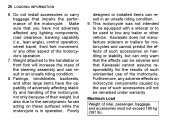
... riding condition. 8. Do not install accessories or carry baggage that Kawasaki cannot assume responsibility for motorcycles and cannot predict the effects of such accessories on handling or stability, but can only warn that the effects can be adverse and that impairs the performance of their weight, but also due to be remedied under warranty. Maximum Load Weight of the steering assembly and...
... riding condition. 8. Do not install accessories or carry baggage that Kawasaki cannot assume responsibility for motorcycles and cannot predict the effects of such accessories on handling or stability, but can only warn that the effects can be adverse and that impairs the performance of their weight, but also due to be remedied under warranty. Maximum Load Weight of the steering assembly and...
Owners Manual
Page 34
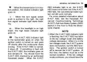
... ignition switch is turned on and goes off shortly after the motorcycle starts moving. For more detailed information about K-ACT ABS, see the Kawasaki Advanced Coactive-braking Technology (K-ACT) Anti-lock Brake System (ABS) section in the How to Ride the Motorcycle chapter. ○When the K-ACT ABS indicator light is flashing, the K-ACT ABS has been in the normal condition. At this time, the battery...
... ignition switch is turned on and goes off shortly after the motorcycle starts moving. For more detailed information about K-ACT ABS, see the Kawasaki Advanced Coactive-braking Technology (K-ACT) Anti-lock Brake System (ABS) section in the How to Ride the Motorcycle chapter. ○When the K-ACT ABS indicator light is flashing, the K-ACT ABS has been in the normal condition. At this time, the battery...
Owners Manual
Page 39
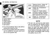
... headlight goes on . Engine off . Audio system, accessory socket, accessory connector, fog light, hazard light equipment can be used . Ignition Key C. OFF Position E. All electrical circuits off . Ignition Switch B. NOTE Engine on when the starter button is in the ON position. ACC Position F. All electrical equipment can be shifted to, by push down and turn on the ignition key. ○The tail, city and license plate lights are on whenever the ignition switch is released...
... headlight goes on . Engine off . Audio system, accessory socket, accessory connector, fog light, hazard light equipment can be used . Ignition Key C. OFF Position E. All electrical circuits off . Ignition Switch B. NOTE Engine on when the starter button is in the ON position. ACC Position F. All electrical equipment can be shifted to, by push down and turn on the ignition key. ○The tail, city and license plate lights are on whenever the ignition switch is released...
Owners Manual
Page 82
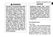
... emission regulation. Turn the ignition switch to detonation or "knocking." Make sure the area is posted on the fuel tank, wipe it off immediately. After refueling, make sure the tank cap is an average of flame or sparks; The octane rating of a gasoline is a measure of 90. The Antiknock Index is closed securely. GENERAL INFORMATION 81 WARNING Gasoline is spilled on service station pumps...
... emission regulation. Turn the ignition switch to detonation or "knocking." Make sure the area is posted on the fuel tank, wipe it off immediately. After refueling, make sure the tank cap is an average of flame or sparks; The octane rating of a gasoline is a measure of 90. The Antiknock Index is closed securely. GENERAL INFORMATION 81 WARNING Gasoline is spilled on service station pumps...

Owners Manual
Page 87
Turn the ignition key counterclockwise, and the passenger's seat is lifted. • • A. 86 GENERAL INFORMATION Seat Passenger's Seat Removal Insert the ignition key into the seat lock. Front Rider's Seat Removal Remove the passenger's seat. Lock B. Passenger's Seat B. Ignition Key up the rear of the rider's seat to clear the hold portions, and then pull the seat to the • Pull front. Pull up the passenger's seat to the rear. • • A.
Turn the ignition key counterclockwise, and the passenger's seat is lifted. • • A. 86 GENERAL INFORMATION Seat Passenger's Seat Removal Insert the ignition key into the seat lock. Front Rider's Seat Removal Remove the passenger's seat. Lock B. Passenger's Seat B. Ignition Key up the rear of the rider's seat to clear the hold portions, and then pull the seat to the • Pull front. Pull up the passenger's seat to the rear. • • A.
Owners Manual
Page 88
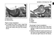
GENERAL INFORMATION 87 A. C. Tab Holder Holes Projections • Passenger's Seat Installation Insert the tab on the rear of the passenger's seat into the slot on the frame. • • Insert the left and right holes on the rear fender. Rider's Seat B. B. Hold Portions Rider's Seat Installation To install the rider's seat, insert the tab at the front of the passenger's seat into the left and right projections at the holder and engage the two grommet holes onto the two projections. A. D.
GENERAL INFORMATION 87 A. C. Tab Holder Holes Projections • Passenger's Seat Installation Insert the tab on the rear of the passenger's seat into the slot on the frame. • • Insert the left and right holes on the rear fender. Rider's Seat B. B. Hold Portions Rider's Seat Installation To install the rider's seat, insert the tab at the front of the passenger's seat into the left and right projections at the holder and engage the two grommet holes onto the two projections. A. D.
Owners Manual
Page 115
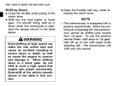
... engine rpm jumps excessively. the throttle half way, while re• Open leasing the clutch lever. ○The transmission is standing still, the transmission cannot be shifted past neutral from 1st gear. Shift into neutral. To use the positive neutral finder, shift down when the motorcycle is operated the speeds shown in the clutch lever. NOTE WARNING Downshifting at high speed can make the rear wheel...
... engine rpm jumps excessively. the throttle half way, while re• Open leasing the clutch lever. ○The transmission is standing still, the transmission cannot be shifted past neutral from 1st gear. Shift into neutral. To use the positive neutral finder, shift down when the motorcycle is operated the speeds shown in the clutch lever. NOTE WARNING Downshifting at high speed can make the rear wheel...
Owners Manual
Page 121
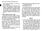
... not go on under motorcycle riding condition. (ex. K-ACT ABS Indicator Light Normally the K-ACT ABS indicator light goes on when the ignition switch is turned on and goes off by an authorized Kawasaki dealer. If the K-ACT ABS fails, the front and rear brakes work normally as a conventional brake system. light remains lit after the motorcycle runs at the speed of approx. 5 km/h (3.1 mph) or below...
... not go on under motorcycle riding condition. (ex. K-ACT ABS Indicator Light Normally the K-ACT ABS indicator light goes on when the ignition switch is turned on and goes off by an authorized Kawasaki dealer. If the K-ACT ABS fails, the front and rear brakes work normally as a conventional brake system. light remains lit after the motorcycle runs at the speed of approx. 5 km/h (3.1 mph) or below...
Owners Manual
Page 132
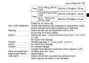
... position by spring tension. Nuts, bolts, fasteners .. Throttle ...Throttle grip play 2 ∼ 3 mm (0.08 ∼ 0.12 in .) left. Brakes ...Brake pad wear: Lining thickness more than 1 mm (0.04 in .). Electrical equipment ...All lights and horn work. Return spring not weak or not damaged. No binding of control cables. Engine stop switch ...Stops engine. Steering ...Action smooth but not loose from lock to lock. Coolant level between level lines (when engine is cold).
... position by spring tension. Nuts, bolts, fasteners .. Throttle ...Throttle grip play 2 ∼ 3 mm (0.08 ∼ 0.12 in .) left. Brakes ...Brake pad wear: Lining thickness more than 1 mm (0.04 in .). Electrical equipment ...All lights and horn work. Return spring not weak or not damaged. No binding of control cables. Engine stop switch ...Stops engine. Steering ...Action smooth but not loose from lock to lock. Coolant level between level lines (when engine is cold).
Owners Manual
Page 143
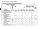
Periodic Inspection (Chassis Related Items) Frequency Whichever comes first Operation (Chassis Items) Clutch operation (play, engagement, disengagement) - inspect 6 months year year *Odometer Reading km × 1000 (mile × 1000) See Page Every 1 6 12 18 24 30 36 (0.6) (3.75) (7.5) (11.25) (15) (18.75) (22.5) Clutch and drive train: 175 175 - - 142 MAINTENANCE AND ADJUSTMENT 2. inspect Clutch fluid level - inspect Clutch fluid leak inspect Clutch hose damage -
Periodic Inspection (Chassis Related Items) Frequency Whichever comes first Operation (Chassis Items) Clutch operation (play, engagement, disengagement) - inspect 6 months year year *Odometer Reading km × 1000 (mile × 1000) See Page Every 1 6 12 18 24 30 36 (0.6) (3.75) (7.5) (11.25) (15) (18.75) (22.5) Clutch and drive train: 175 175 - - 142 MAINTENANCE AND ADJUSTMENT 2. inspect Clutch fluid level - inspect Clutch fluid leak inspect Clutch hose damage -
Owners Manual
Page 146
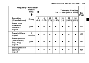
MAINTENANCE AND ADJUSTMENT 145 Frequency Whichever comes first Operation (Chassis Items) Brake hose installation condition inspect *Odometer Reading km × 1000 (mile × 1000) See Page Every 1 6 12 18 24 30 36 (0.6) (3.75) (7.5) (11.25) (15) (18.75) (22.5) year 177 6 Brake fluid level months inspect Brake operation (effectiveness, play, drag) inspect Brake light switch operation inspect year 177 180 181
MAINTENANCE AND ADJUSTMENT 145 Frequency Whichever comes first Operation (Chassis Items) Brake hose installation condition inspect *Odometer Reading km × 1000 (mile × 1000) See Page Every 1 6 12 18 24 30 36 (0.6) (3.75) (7.5) (11.25) (15) (18.75) (22.5) year 177 6 Brake fluid level months inspect Brake operation (effectiveness, play, drag) inspect Brake light switch operation inspect year 177 180 181
Owners Manual
Page 152
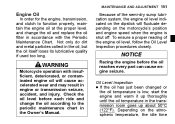
... Owner's Manual. • MAINTENANCE AND ADJUSTMENT 151 In order for the engine, transmission, and clutch to function properly, maintain the engine oil at the proper level, and change the oil according to the periodic maintenance chart in engine or transmission seizure, accident, and injury. Engine Oil Because of the engine oil level, follow the Oil Level Inspection procedures closely. Oil Level Inspection If the oil has just been changed or the oil...
... Owner's Manual. • MAINTENANCE AND ADJUSTMENT 151 In order for the engine, transmission, and clutch to function properly, maintain the engine oil at the proper level, and change the oil according to the periodic maintenance chart in engine or transmission seizure, accident, and injury. Engine Oil Because of the engine oil level, follow the Oil Level Inspection procedures closely. Oil Level Inspection If the oil has just been changed or the oil...
Owners Manual
Page 182
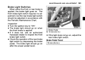
... rear brake light switch by depressing the brake pedal. Brake Pedal Travel 10 mm (0.4 in accordance with the Periodic Maintenance Chart. Brake Pedal B. 10 mm (0.4 in.) the light does not go on , adjust the • If rear brake light switch. If it does not, ask an authorized Kawasaki dealer to "ON". The brake light should be adjusted in .) Brake Light Switches A. Inspection Turn the ignition key to inspect the front brake light switch. The front brake light switch...
... rear brake light switch by depressing the brake pedal. Brake Pedal Travel 10 mm (0.4 in accordance with the Periodic Maintenance Chart. Brake Pedal B. 10 mm (0.4 in.) the light does not go on , adjust the • If rear brake light switch. If it does not, ask an authorized Kawasaki dealer to "ON". The brake light should be adjusted in .) Brake Light Switches A. Inspection Turn the ignition key to inspect the front brake light switch. The front brake light switch...
Owners Manual
Page 183
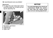
B. C. 182 MAINTENANCE AND ADJUSTMENT Adjustment To adjust the rear brake light switch, move the switch up or down by turning the adjusting nut. • NOTICE To avoid damaging the electrical connections inside the switch, be sure that the switch body does not turn during adjustment. Lights Later. D. Rear Brake Light Switch Adjusting Nut Lights Sooner. A.
B. C. 182 MAINTENANCE AND ADJUSTMENT Adjustment To adjust the rear brake light switch, move the switch up or down by turning the adjusting nut. • NOTICE To avoid damaging the electrical connections inside the switch, be sure that the switch body does not turn during adjustment. Lights Later. D. Rear Brake Light Switch Adjusting Nut Lights Sooner. A.
Owners Manual
Page 206
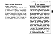
... mechanical problems and increase the risk of fire. If debris or flammable materials have collected, park the vehicle outside and stop the engine. Do not park or store the vehicle in and around the vehicle, inspect the engine, electrical component and exhaust areas frequently. When operating the vehicle in conditions that allow debris or flammable material to cool, then remove any collected debris. MAINTENANCE AND...
... mechanical problems and increase the risk of fire. If debris or flammable materials have collected, park the vehicle outside and stop the engine. Do not park or store the vehicle in and around the vehicle, inspect the engine, electrical component and exhaust areas frequently. When operating the vehicle in conditions that allow debris or flammable material to cool, then remove any collected debris. MAINTENANCE AND...
Owners Manual
Page 214
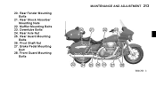
Muffler Mounting Bolts 23. Downtube Bolts 24. Rear Guard Mounting Bolts 26. Pivot Shaft Nut 27. MAINTENANCE AND ADJUSTMENT 213 20. Rear Shock Absorber Mounting Nuts 22. Rear Fender Mounting Bolts 21. Rear Axle Nut 25. Brake Pedal Mounting Bolt 28. Front Guard Mounting Bolts
Muffler Mounting Bolts 23. Downtube Bolts 24. Rear Guard Mounting Bolts 26. Pivot Shaft Nut 27. MAINTENANCE AND ADJUSTMENT 213 20. Rear Shock Absorber Mounting Nuts 22. Rear Fender Mounting Bolts 21. Rear Axle Nut 25. Brake Pedal Mounting Bolt 28. Front Guard Mounting Bolts
Owners Manual
Page 216
... water and consult a physician as soon as possible. Turn the ignition key to coat the cylinder walls. Contact your local authorities for a few seconds to "OFF". the fuel system by running the engine at idle speed until all fuel in the fuel • Empty system is a toxic substance. Gasoline is used up (If left in your eyes. Remove the spark plugs and spray fogging oil directly...
... water and consult a physician as soon as possible. Turn the ignition key to coat the cylinder walls. Contact your local authorities for a few seconds to "OFF". the fuel system by running the engine at idle speed until all fuel in the fuel • Empty system is a toxic substance. Gasoline is used up (If left in your eyes. Remove the spark plugs and spray fogging oil directly...