
Weider Pro 4500 Support Question
Weider Pro 4500 Support Question
Find answers below for this question about Weider Pro 4500.Need a Weider Pro 4500 manual? We have 5 online manuals for this item!
Question posted by godesslizzie on May 5th, 2015
Cannot Connect Leg Raise Cable
Have set up the gym but can not see how to set lower cable?
Current Answers
Related Weider Pro 4500 Manual Pages
Uk Manual - Page 2
... warning decal(s). TABLE OF CONTENTS
WARNING DECAL PLACEMENT 2 IMPORTANT PRECAUTIONS 3 BEFORE YOU BEGIN 5 PART IDENTIFICATION CHART 6 ASSEMBLY 7 ADJUSTMENT 23 WEIGHT RESISTANCE CHART 25 CABLE DIAGRAMS 26 MAINTENANCE 27 EXERCISE GUIDELINES 28 PART LIST 29 EXPLODED DRAWING 30 ORDERING REPLACEMENT PARTS Back Cover
WARNING DECAL PLACEMENT
This drawing shows the location(s) of this...
Uk Manual - Page 4
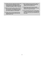
...exercising to tip.
16. If the cables bind as you experience pain while exercising, stop immediately and make sure that the cables remain on the pulleys.
15. Never release the arms, leg lever, lat bar, or ankle strap while weights are exercising... when performing an exercise that does not require the lat bar.
18. If you feel faint or if you are raised. Over exercising may result in ...
Uk Manual - Page 5
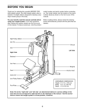
...this manual carefully before contacting us assist you for selecting the versatile WEIDER® PRO 4500 weight system. The model number and the location of the body. For your weight....
To help us . High Pulley Station Arm Pin
Arm Right Side Backrest
Shroud Left Side
Curl Pad
Seat Leg Lever Low Pulley Station
Foot Plate
Weights Anchor Hole*
ASSEMBLED DIMENSIONS: Height: 6 ft. 4 in. (193...
Uk Manual - Page 7
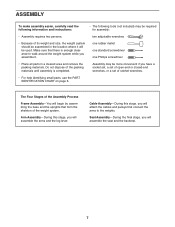
...set of ratchet wrenches.
• For help identifying small parts, use the PART IDENTIFICATION CHART on page 6. The Four Stages of the weight system. Cable Assembly-During this stage, you assemble it will attach the cables... the base and the uprights that connect the arms to walk around the weight system while you will assemble the arms and the leg lever. two adjustable wrenches
•...
Uk Manual - Page 9

...Attach the Seat Frame (6) to the Front Leg (7) with the
3
two indicated M8 x 75mm Carriage Bolts (78)
and two M8 Locknuts (58). 3. Attach the Leg Bumper (60) to the Front Leg (7) in the same manner.
4
68... Hold the Seat Frame (6) between the Upright (3) and the Front Leg (7). Orient the Seat Frame so that the end of the Leg Bumper is pointing upward. Do not tighten the
Locknuts yet. Up
...
Uk Manual - Page 12

...
69
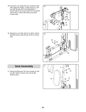
Shroud. Make sure that the welded support is on the
Stabilizer (2) with the Bolt Set. Attach the Shroud (17) to the Top Frame (4) with two M4 x 19mm Screws (69).
8
4
Attach the Shroud (17) to the Front Leg (7) with two M4 x 19mm Screws (69). See steps 2-6. Tighten the Locknuts (56, 58)
69...
Uk Manual - Page 13
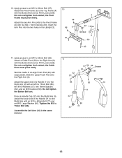
... x 90mm Bolt (67). Do not tighten the Button Bolt yet. 10. Do not overtighten the Locknut;
the Cable Pivot must pivot freely. Press a Handle Cap (31) into the two holes in the same manner.
11
52...Pins (40) to the Top Frame (4) with the Button Bolt and an M10 Locknut (56). Attach the lower end of the Handle (11) to the Right Arm (9) with soapy water. Slide the Large Foam Pad ...
Uk Manual - Page 14
...
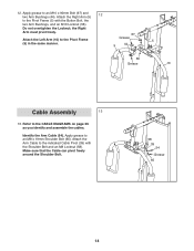
Identify the Arm Cable (54). the Right
Arm must pivot freely. Apply grease to the CABLE DIAGRAMS on page 26 as you identify and assemble the cables. Attach the Arm Cable to the Pivot Frame... in the same manner.
67
Grease
5
9
44
56
Grease
10
Cable Assembly
13
13. 12. Attach the Right Arm (9)
12
to the indicated Cable Pivot (39) with the Button Bolt, the
two Arm Bushings, and...
Uk Manual - Page 15

...) and an M10 Locknut
(56). 14. Route the Arm Cable (54) over a V-pulley (46).
16
Attach the V-pulley, a Large Cable Trap (50),
and two Guards (41) to hold the Cable in the groove of the
V-pulley.
3
56 41 46...
41
54
50
75
15. Make sure that the Cable Trap is ori- Route the Arm Cable (54) under a 90mm Pulley (48). Make sure that the Half Guards are on...
Uk Manual - Page 16

...the Top Frame while you complete steps 20
and 21.
47
55
4
33 57 71
16 Route the High Cable up through the Top Frame (4) and over a 90mm Thin Pulley (47) and down through the Top Frame
19...56).
57
56 33
55 4
48
33 57 71
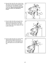
19. Route the High Cable (55) over a
18
90mm Pulley (48). Identify the High Cable (55). Attach the Arm Cable (54) to an M8 x 19mm Shoulder Bolt (65). Grease 65
54 ...
Uk Manual - Page 17
...20. bracket.
21. Make sure that the Half Guards
are on the outside of the Adjustable U- Route the High Cable (55) up through the Top Frame (4) and over a 90mm Pulley (48) and down through the Top Frame ...Spacers (33), and an M10 Locknut
(56).
56 33
57 4
48
55 33 57
71
17 Route the High Cable (55) over a 90mm Thin Pulley (47).
21
Attach the Thin Pulley inside the Top Frame with an M10 ...
Uk Manual - Page 18

... Spacers (52), and an M10 Locknut (56).
8 56 52 57
53
48
7 57
52 85
25. Attach a 90mm Pulley (48) inside the Front Leg (7), over the Low Cable (53), with an M10 x 80mm Bolt (71), two M10 Washers (57), two 19mm Spacers (33), and an M10 Locknut (56).
25
57 56
33...
Uk Manual - Page 19
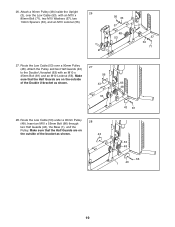
...an M10 x 55mm Bolt (66) through two Half Guards (43), the Base (1), and the Pulley. Route the Low Cable (53) under a 90mm Pulley (48). Make sure that the Half Guards are on the outside of the Double U-bracket ... 90mm Pulley (48) inside the Upright (3), over a 90mm Pulley (48). Route the Low Cable (53) over the Low Cable (53), with an M10 x 45mm Bolt (81) and an M10 Locknut (56). 26.
Uk Manual - Page 20
... M6 x 80mm Screws (70) and two M6 Washers (82).
16
3 70
82
82 70
20 29.
Route the Low Cable (53) over a 90mm Pulley
29
(48). Attach the Backrest (16) to the Adjustable U- bracket (45) at the second...66) and an M10
Locknut (56).
56
66
43 51
45 43 48 53
30. Attach the Pulley, a Cable Trap (51), and
two Half Guards (43) to the Upright (3) with an M10 Locknut
30
(56).
56 53
66...
Uk Manual - Page 21

....
28
34
28 8
7 28 34
21 Slide two Small Foam Pads (28) onto the Pad Tube. Insert the Pad Tube (29) into the Front Leg (7). Attach the Seat (15) to the Seat Frame (6) with two M6 x 80mm Screws (70) and two M6
32
Washers (82).
15
6 82 70
33. Then, ...
Uk Manual - Page 22
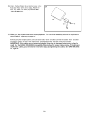
...weight system, pull each cable a few times to the lower edge. If one of the cables does not move smoothly around the pulleys. IMPORTANT: If the cables are closer to make sure that the cables move smoothly, find ... Make sure that the holes in the back are not properly installed, they may be explained in the cables, you will need to the Curl Post (13) with two M6 x
16mm Screws (62).
14...
Uk Manual - Page 23
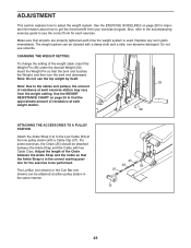
... Pin (26) under the desired Weight (22). Use the WEIGHT RESISTANCE CHART on page 28 for the exercise to get the most benefit from the weight setting. Adjust the length of the Chain between the Ankle Strap and the Cable with a damp cloth and a mild, non-abrasive detergent. Also, refer to the accompanying...
Uk Manual - Page 24
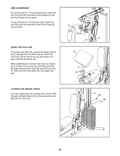
... use the Arms (9, 10) as press arms, insert the Arm Pins (40) into the Front Leg and secure it in place with the Curl Knob (61). Insert the Curl Post (13) into the holes ...Lock (88) onto the Lock Pin.
3 40 9
Holes 5 10
14
13 30
61 7
21 88 89
24 When performing an exercise that does not require the Curl Pad (14), remove the Curl Pad and insert the 64mm Round Inner Cap (30) into the holes...
Uk Manual - Page 25
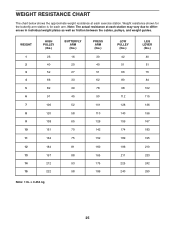
Note: The actual resistance at each exercise station. WEIGHT
1 2 3 4 5 6 7 8 9 10 11 12 13 14 15... PULLEY
(lbs.) 42 51 66 80 98 112 128 140 159 174 189 196 211 225 240
LEG LEVER (lbs.)
40 51 70 84 102 115 136 156 167 183 195 210 233 242 250
Note...plates as well as friction between the cables, pulleys, and weight guides. Weight resistance shown for the butterfly arm station is for each arm.
Uk Manual - Page 29
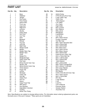
...Large Cable Trap
51
1
Cable Trap
52
6
16mm Spacer
53
1
Low Cable
54
1
Arm Cable
55
1
High Cable
56 23 M10 Locknut
57 20 M10 Washer
58 12 M8 Locknut
59
6
M8 Washer
60
1
Leg Bumper
...4
M6 x 80mm Screw
71
5
M10 x 80mm Bolt
72
2
64mm Round Outer Cap
73
1
M10 x 70mm Bolt Set
74
1
M10 x 160mm Bolt
75
2
M10 x 65mm Bolt
76
2
13mm Spacer
77
2
M10 x 40mm Bolt
78...
Similar Questions

Weirder Pro Universal 9648 Exercise Chart
I just bought a used Pro 9648 Universal Gym and would love an exercise chart. I know there are more ...
I just bought a used Pro 9648 Universal Gym and would love an exercise chart. I know there are more ...
(Posted by lynewman1011 10 months ago)

I'm Looking To Order Complete Cables To The Weider Pro 9940
(Posted by Hef2324 1 year ago)

Exercise Workout.
Hi i have just purchased a second hand Weider pro 4500 multi gym and have spent hours searching the ...
Hi i have just purchased a second hand Weider pro 4500 multi gym and have spent hours searching the ...
(Posted by jackfizzer 4 years ago)
I Need The Leg Press Cable
wcablewhat is the part number for the leg press cable on the 9835 model?
wcablewhat is the part number for the leg press cable on the 9835 model?
(Posted by sehongang 5 years ago)

How To Adjust The Weight Resistance
How do I vary the weight amounts for the various exercises?
How do I vary the weight amounts for the various exercises?
(Posted by plantguy 6 years ago)