Get support for Sony ICF-SW7600GR - Portable Radio

Sony ICF-SW7600GR Support Question

Sony ICF-SW7600GR Support Question

Find answers below for this question about Sony ICF-SW7600GR - Portable Radio.
Need a Sony ICF-SW7600GR manual? We have 2 online manuals for this item!
Question posted by rcrosman on September 28th, 2013

Sony Icf-sw7600gr Does Not Turn On Operating Only With New Batteries.

After a battery leakage, the battery compartment was wiped thoroughly before installing the new batteries, and the radio Sony ICF-SW7600GR was working perfectly with only batteries or with batteries and the AC power adaptor 6 V. Some months later, the Sony ICF-SW7600GR with only new batteries installed began to not turn on anymore when the Power On/Off button is pressed, and to show the icon of completely exhausted batteries. But when it is operated by connecting the AC power adaptor to the DC IN 6 V jack, and with the new batteries installed too, the radio does not show the icon of completely exausted batteries and works perfectly. When the radio is turned off (operating with the new batteries and the AV power adaptor together) the display shows the Time correctly (does not show the icon of completely exausted batteries). What should I do to repair the radio to make it to operate using only the new batteries without the AC power adaptor? Thank you for your kind attention Renato Rio de Janeiro, Brazil

Current Answers

Answer #1: Posted by BusterDoogen on September 28th, 2013 12:28 PM
This answer was accepted by the poster of the original question.
BusterDoogen

Member since:
October 30th, 2011

Points: 28,565,447
1,110
points
I suggest you check your battery connectors thoroughly because one or more of the contact points is corroded enough to short the circuit. Good luck!

Please respond to my effort to provide you with the best possible solution by using the "Acceptable Solution" and/or the "Helpful" buttons when the answer has proven to be helpful. Please feel free to submit further info for your question, if a solution was not provided. I appreciate the opportunity to serve you!

Answer #2: Posted by rcrosman on September 29th, 2013 1:27 PM
rcrosman

Member since:
September 28th, 2013

Points: 50
100
points
The two metallic terminals that contact the two battery positive terminals have a poor design because these cited two metallic terminals have a very small contact surface area. They are made of a thin rectilineal metallic wire. After a battery leakage it is very important to wipe as soon as possible and thoroughly all the four radio metallic terminals (two rectilineal and two spring terminals) and the battery compartment using a long wood rod containing a cotton swab on one of its extremity moistened with isopropyl alcohol. If there is some corrosion on the terminals' metal surfaces, it should be removed too. The four radio metallic terminals should be totally clean. Normally after this procedure, the new batteries could be inserted and the radio would turn on without problem.

Note: Take care when using isopropyl alcohol. Avoid the leakage of isopropyl alcohol into the radio circuit boards, or the contact of the radio cabinet, the radio side panels, the radio control buttons and the radio display with isopropyl alcohol. The cotton swab moistened with isopropyl alcohol should be washed with plenty water before throw it away. Isopropyl alcohol is flammable.

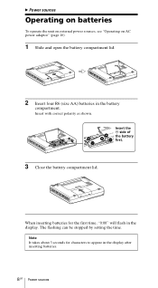
If the radio does not turn on after the cleaning procedure explained above, use the following method to solve the problem of bad contact between the radio rectilineal metallic terminals and the respective batteries' positive terminals:

Cut two strips of aluminium foil having the width of 2 cm and the length of 3 cm. Fold the width of 2 cm in the middle to make a strip having a width of 1 cm. Then, put each aluminium foil strip (width of 1 cm and length of 3 cm) on the center of each battery positive terminal of the two bateries that will contact the cited two metallic thin rectilineal terminals of the radio battery compartment. The two extremities having the length of 1 cm of each aluminium foil should be attached on each of the two battery side walls using an adhesive tape like "3M Scotch tape" to avoid that the positive and negative metallic radio terminals are accidentally contacted with each other by the aluminium foil. Insert the new batteries into the battery compartment positioning each of the two batteries having the positive terminal wrapped with the aluminium foil strip in contact with each of the respective radio metallic rectilineal terminal.

The aluminium foil strip helps to increase the contact surface area of the positive battery terminal and solves the problem of bad contact with the radio metallic rectilineal terminals. Now the radio will turn on using only the four new batteries installed.

The radio manual informs: "Do not carry the dry batteries with coins or other metallic objects. It can generate heat if the positive and negative terminals of the batteries are accidentally contacted by a metallic object".

If you follow the method as explained above, the problem of heat generation will not occur.

Related Sony ICF-SW7600GR Manual Pages

Operating Instructions - Page 1

3-227-586-13 (1) FM Stereo/SW/MW/LW PLL Synthesized Receiver Operating instructions GB Mode d'emploi FR Bedienungsanleitung DE Manual de instrucciones ES Gebruiksaanwijzing NL Manual de Instruções PT ICF-SW7600GR Sony Corporation 2001 Printed in Japan
Operating Instructions - Page 2

... to suit your authority to operate this unit is encouraged to try to 9 kHz or 10 kHz. ICF-SW7600GR Serial No Warning To prevent fire or shock hazard, do not open the cabinet. Changing the settings to be determined by turning the equipment off the radio so that interference will automatically turn off and on, the...
Operating Instructions - Page 3

... 3GB Synchronous detection 27 Using the timer Waking up to the radio - Table of contents Introduction Location of parts and controls 4 Power sources Operating on batteries 8 Operating on external power sources 10 Operating on radio waves 41 Table of the world ... 13 Listening to the radio Changing MW Channel Step 15 GB Directly entering the frequency - Auto...
Operating Instructions - Page 8

...00" will flash in the display. When inserting batteries for characters to appear in the battery compartment. Insert the # side of the battery first. 3 Close the battery compartment lid. B Power sources Operating on batteries To operate the unit on external power sources, see "Operating on AC power adaptor" (page 10). 1 Slide and open the battery compartment lid. 2 Insert four R6 (size AA...
Operating Instructions - Page 9

... (constant display), the power will turn off . Should any battery leakage occur, wipe the battery compartment thoroughly before installing new batteries. After replacing the batteries and turning on the power again, "E" will disappear and the unit will become weak. Replace all buttons will become inoperable. Battery life (JEITA*) Sony LR6 alkaline (size AA) Sony R6 (size AA) FM approx...
Operating Instructions - Page 10

... external power source is not to the Polarity of whether the batteries are installed. Using AC power adaptors with different specifications (polarity of the plug, etc.) will not operate on batteries as long as backup for a long period of the unit. In this case, turn on the power again to clear the "E" display. • When...
Operating Instructions - Page 38

... display is activated. The HOLD function is not operating. There is being used in extremely low temperature or in a vehicle or building. c Replace with new batteries. Weak radio signal. You pressed an incorrect number button for repair. c Properly connect the AC power adaptor. The volume is turned down ENTER and press a number button (0-9) (page 22...
Service Manual - Page 1

...batteries) Supplied accessories Carrying case (1) Compact antenna AN-71 (1) Wave Handbook (1) Design and specifications are subject to change without notice. 9-873-099-11 2001C1600-1 © 2001.3 Sony Corporation Audio Entertainment Group General Engineering Dept. ICF-SW7600GR...Output LINE OUT jack (stereo minijack) × 1 Recording output level approx. 245 mV, output impedance less than...
Service Manual - Page 3

.... At this button to the unit . Furthermore, do not use . Front SECTION 1 GENERAL Rear ICF-SW7600GR This section is on will turn off the light. Pressing the button again while the light is extracted from the speaker will be sure to push in the base as well. Base qj Stand Pull out qk Battery compartment 3
Service Manual - Page 4

...Battery indicator (9) 3 HOLD indicator (32) Appears when HOLD is on. 0 Time/frequency display 4 If you do not press the button, the display will be inoperative. 4 (Daylight Saving Time) indicator (12) Appears when the time display is adjusted to clock display while operating the radio. ICF-SW7600GR...standby timer is set. 9 PAGE number display Appears constantly when the radio is in effect.
Service Manual - Page 5

... has ended, press DST to clock display while the radio is the time for the first time or when the unit has been reset. Tips • The clock is turned on Press EXE. ICF-SW7600GR Setting the Current Time "0:00" flashes in the display when installing the batteries for your local time and the UTC. Note...
Service Manual - Page 6

... than 2.2V. 4. IF the value is more than 13V, adjust T202 so that the reading on the digital voltmeter becomes in the numerical order given. 2-1. ICF-SW7600GR SECTION 2 DISASSEMBLY Note : Follow the disassembly procedure in 12.5V. CABINET (REAR) 2 Two screws (+BTP 3 × 25) 1 Three screws (+BTP 3 × 25) 4 Cabinet (rear) 3 Four...
Service Manual - Page 7

... Adjust RV202 so that the beat sound is changed by turning the SSB FINE TUNE control. Adjustment Location: MAIN board...level : 44dB Procedure: 1. Repeat the above steps 1 to FM 108.00MHz. 2. ICF-SW7600GR (3) 2nd Local Adjustment Setting: ATT switch : OFF TONE switch : MUSIC AM MODE... jack (J202) (for VCO operation). 2. Repeat the above steps 4 to FM 76.00MHz. 4. ...
Service Manual - Page 9

... • Abbreviation CH: Chinese model EA: Saudi Arabia model : SW BATT EXCEPT CH J203 DC IN 6V DRY BATTERY SIZE"AA" (IEC DESIGNATION R6) 4PCS,6V 9 9 SSB SYNC NORM - BLOCK DIAGRAM SECTION 4 DIAGRAMS ICF-SW7600GR ANT101 (TELESCOPIC) FM TRACKING T101 CT101 FM ANT J101 AM EXT ANT (EXCEPT CH) Q120 ATT VT Q101...
Service Manual - Page 10

...hole. • : Pattern from the parts face are not indicated.) • Abbreviation CH : Chinese model. ICF-SW7600GR 4-2. No. No. No. No. No. Parts on the parts face side seen from the side which enables...F-11 Q222 F-12 Q223 F-11 Q224 F-12 Q225 F-12 10 10 SP201 SPEAKER 8Ω K A DRY BATTERY SIZE "AA" (IEC DESIGNATION R6) 4PCS. 6V K A CH A K J203 DC IN 6V 11 1-...
Service Manual - Page 11

PRINTED WIRING BOARD - 4-3. Parts on the pattern face side seen from the parts face are indicated. A MAIN BOARD (COMPONENT SIDE) B ICF-SW7600GR C D E F US G B H TO KEY BOARD I 11 1-679-368- (11) 15 16 17 18 19 20 21 22 23 24 25 26 27 28 11 11 Note ...
Service Manual - Page 12

... except for electrolytics and tantalums. • All resistors are in µF unless otherwise noted. F : FM L : MW/LW h : SW • Abbreviation CH : Chinese model SCHEMATIC DIAGRAM - ICF-SW7600GR 4-4.
Service Manual - Page 17

..., RUBBER CABINET (REAR) (EXCEPT CH) CABINET (REAR) (CH) LID, BATTERY CASE ANTENNA, TELESCOPIC 10 3-227-401-01 PLATE (ANT), CONTACT Remarks 17 CABINET SECTION 7 2 5 4 5 36 89 1 ANT101 12 10 15 13 15 14 15 16 17 18 11 Ref. SECTION 5 EXPLODED VIEWS ICF-SW7600GR NOTE: • -XX, -X mean standardized parts, so they may...
Service Manual - Page 18

...-396-01 3-227-392-01 3-227-389-01 1-694-751-11 3-227-390-01 TERMINAL (+), BATTERY CHASSIS HOLDER (LCD) CONDUCTIVE BOARD, CONNECTION CASE (LCD) A-4440-288-A MAIN BOARD, COMPLETE (EXCEPT...BOARD, COMPLETE (CH) 3-227-397-01 TERMINAL (-), BATTERY ANT102 1-402-479-21 ANTENNA, FERRITE-ROD (LW/MW) LCD1 1-804-194-11 DISPLAY PANEL, LIQUID CRYSTAL SP201 1-529-942-11 SPEAKER (7.7cm) 18 ICF-SW7600GR 5-2.
Service Manual - Page 26

Ver. Date 1.0 2001.03 New Description of Revision ICF-SW7600GR REVISION HISTORY Clicking the version allows you to jump to the revised page. Also, clicking the version at the upper right on the revised page allows you to jump to the next revised page.

Similar Questions

There Is No Audio From The Sony Wm-fx281 At All....new Batteries, New Earplugs
Does replacing the "Head Assembly" correct the problem of no Audio at all from my Sony WM-FX281 ? Ev...
(Posted by gmtb5 8 years ago)
No Sound Coming Out Of Sony Wm-fx281 -- New Batteries, New Earplugs And The Disp
My Sony WM-FX281 has new batteries, new earplugs (tested on another Sony) and everything appears to ...
(Posted by gmtb5 8 years ago)
How To Cancel Alarm Function On Sony Icf-sw7600gr
I Have The Manual, I Know How To Read, Page 29 Is Clear, Press Standby Memory A Or B With The Radio ...
(Posted by mtztmjd 8 years ago)
Ask a New Question
Use the box below to post a new question about this Sony product .
Points & Prizes
  • You can earn points for nearly everything you do on HelpOwl.com
  • You can trade in those points for gift cards at leading retailers such as Amazon.com and Walmart
  • It's that simple!
See How it Works
Create a Free Account

Sony Manuals

Find free Sony ICF-SW7600GR - Portable Radio manuals and user guides available at ManualOwl.com. Try out our unique manual viewer allowing you to interact with manuals from directly within your browser!

Sony Reviews

View thousands of Sony user reviews and customer ratings available at ReviewOwl.com.

Contact Information

Complete Sony customer service contact information including steps to reach representatives, hours of operation, customer support links and more from ContactHelp.com.

Scoreboard Ratings

See detailed Sony customer service rankings, employee comments and much more from our sister site.

Sony Recalls

Find comprehensive Sony recall information updated hourly on RecallOwl.com.