Sony HCD-SH2000 Support Question
Sony HCD-SH2000 Support Question
Find answers below for this question about Sony HCD-SH2000.Need a Sony HCD-SH2000 manual? We have 1 online manual for this item!
Question posted by Jenicksbobin on April 9th, 2021
My Amp Is Showing Protected
my AMp is showing protected
Current Answers
Answer #1: Posted by Troubleshooter101 on April 9th, 2021 1:49 PM
Troubleshooter101

Member since:
September 30th, 2015 Points: 2,927,030

Member since:
September 30th, 2015 Points: 2,927,030
If you find that one pair of speaker wires or one speaker causes the amp to go into protect, disconnect all speakers from the other end of the wires and separate the wires so they can't touch. If the amp still goes into protect, you have a bad speaker wire or the wire is shorted to chassis ground.
https://www.sony.co.in/electronics/support/articles/00025095
Thanks
Please respond to my effort to provide you with the best possible solution by using the "Acceptable Solution" and/or the "Helpful" buttons when the answer has proven to be helpful. Please feel free to submit further info for your question, if a solution was not provided. I appreciate the opportunity to serve you!
Troublshooter101
Related Sony HCD-SH2000 Manual Pages
Service Manual - Page 1
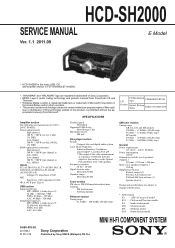
... intellectual property rights of 200 mm from Microsoft. HCD-SH2000
SERVICE MANUAL
E Model
Ver. 1.1 2011.09
• HCD-SH2000 is the tuner, USB, CD and amplifier section in FST-SH2000/LBT-SH2000.
• "WALKMAN" and "WALKMAN" logo are registered trademarks of Sony Corporation. • MPEG Layer-3 audio coding technology and patents licensed from Fraunhofer IIS...
Service Manual - Page 2
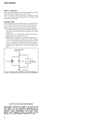
...for AC leakage. Follow the manufacturers' instructions to check AC leakage.
REPLACE THESE COMPONENTS WITH SONY PARTS WHOSE PART NUMBERS APPEAR AS SHOWN IN THIS MANUAL OR IN ...VOM or battery-operated AC voltmeter. The Data Precision 245 digital multimeter is suitable. A. HCD-SH2000
SAFETY CHECK-OUT After correcting the original service problem, perform the following safety check before ...
Service Manual - Page 3
...Chassis Section 68 6-5. DIAGRAMS 5-1. AMP Section 17 5-4. MAIN Board (Component Side) (Suffix 11...fix 11) -... 27 5-13. DMB21 Board (2/3 35 5-21. AUDIO-IN Board 51 5-38. Front Panel Section (1 66 6-3. ELECTRICAL PARTS LIST...Schematic Diagram - DMB21 Board (Conductor Side 33 5-19. HCD-SH2000
TABLE OF CONTENTS
1. DMB21 Board 8 2-5. CD MECHANISM...
Service Manual - Page 4
...area called the Lead-in expansion format), or Multi Session 3)
1) MP3 (MPEG 1 Audio Layer 3) is a disc having multiple sessions, with
the lead free mark due to their... a tantalum capacitor may be handled with single.
HCD-SH2000
Ver. 1.1
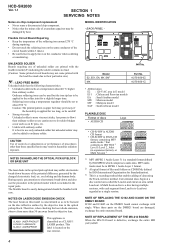
SECTION 1 SERVICING NOTES
Notes on chip component replacement • Never reuse a disconnected chip component. • Notice that conforms to ISO 9660...
Service Manual - Page 5
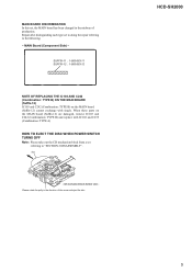
...) are damaged, remove IC103 and C242 (Combination: TYPE B) and replace with single. CD mechanism block bottom view - HCD-SH2000
5
Please rotate the pully in the midway of the arrow and eject the disc. MAIN Board (Component Side) - disc
-
When these parts on the MAIN board (Suffix-12) cannot exchange with IC102 and...
Service Manual - Page 11
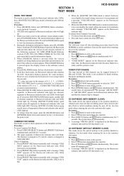
...displays "K 0 V0". When [SOUND FLASH] button is pressed, the fluorescent indicator tube shows the version of fluorescent indicator tube will light
up . Pressing [SOUND FLASH] button again... tube and the CD ship mode is set to the customer. SECTION 3 TEST MODE
HCD-SH2000
PANEL TEST MODE This mode is turned counterclockwise even slightly, the sound volume decreases to its...
Service Manual - Page 14
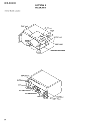
HCD-SH2000
• Circuit Boards Location
SECTION 5 DIAGRAMS
DAMP board
MS-214 board TUNER MAIN board
DMB21 board SWITCHING REGULATOR
DISPLAY board BUTTON board
MIC board
BUTTON LED board VOLUME LED board USB board
VOLUME board AUDIO-IN board
14
Service Manual - Page 16
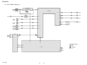
... BLOCK DIAGRAM -
SIGNAL PATH
: AUDIO : TUNER (FM/AM) : MIC
HCD-SH2000
16
16 J1300 MIC IN
A (Page 15)
L-OUT
J1200
TV R-CH
J1201
PC
GAME AUDIO IN
DVD/SAT AUDIO IN
J500 L R L R
R-CH R-CH R-CH
IC1300 MIC AMP
5
7
3
1
RV1300
MIC LEVEL MIN MAX
IC501 OP AMP
5
7
46 MIC
39 GAME_L ...XC-IN 10 XC-OUT 11
X113 8MHz
X110 32.768kHz
R-ch is omitted due to same as L-ch. HCD-SH2000
5-2.
Service Manual - Page 17
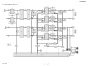
...+ OUTPUT 1
7 OUTPUT INPUT+ 3
3 INPUT+ OUTPUT 1
MUTE Q601
OP AMP IC805
5 INPUT+ OUTPUT 7
C Lch
(Page 16)
R-CH
3 INPUT+ OUTPUT 1
MUTE Q600
OP AMP IC600
5 INPUT+ OUTPUT 7
SIGNAL PATH
: AUDIO
MUTE Q207
51
/LINE-MUTE DAMP-CLK /DAMP-RESET
NO USE /SD-SLOW RESONANCE
D1403 D1435
HCD-SH2000
LOW SPEAKER IMPEDANCE USE 4ȍ
2 INA- AOUT 1
PREAMP IC1403...
Service Manual - Page 18

...53 SPK-L-LED-BLUE
PCONT-MAIN 63 PCONT-SUB 59
54 SPK-R-LED-RED 55 SPK-R-LED-BLUE
HCD-SH2000
AVDD +5V DVDD +5V
RF +3.3V
+3.3V REGULATOR
IC107
TU +3.3V VBUS +5V
LED +...
+1.8V REGULATOR
IC111
+4V REGULATOR
IC102
+4V REGULATOR
IC103
SWITCHING Q805
+3.3V REGULATOR
IC801
+13V
G (Page 17)
AMP RESET Q1475
μ COM RESET Q200
μ COM RESET IC101
+53V +18V +5.0V
+18V REGULATOR
IC1400
+5.0V ...
Service Manual - Page 19

...Indication of transistor
C
Q
These are omitted.
Replace only with a oscilloscope. Note: The components identified by mark 0 or dotted line with a VOM (Input impedance 10 MΩ...fied.
• A : B+ Line. • B : B-
F : AUDIO E : USB f : TUNER J : AUDIO (DIGITAL)
• Abbreviation E2 : 120 V AC area in μF unless otherwise...HCD-SH2000
19
19
HCD-SH2000
Ver. 1.1
Service Manual - Page 20

...AUDIO-IN
H BOARD NO1200 (Page 51)
11 (11)
CN704
CN705
(CHASSIS)
G
DAMP BOARD CN1400 (Page 37)
B
DAMP BOARD CN1401 (Page 37)
J
HCD-SH2000
20
20
Note: Refer to distinguish SUFFIX-11 and SUFFIX-12. HCD-SH2000
5-5.
MAIN BOARD (Component... F
-&%
41&",&3
3
G
H
I
F700
3
1
3
1
J500
MAIN BOARD
(Component side)
DMB21
I BOARD CN4604 (Page 32)
DMB21
F BOARD CN602 (Page 32)
(...
Service Manual - Page 22

...
11
12
13
14
15
A
MAIN BOARD (Component side)
B
TUNER
J BOARD
CN1601 (Page 49)
C
(".&
"6%*0 */
-3
D
%7%4"5
"6%*0 */
-3
E
- C345
USB
C BOARD NO1152 (Page 47)
VOLUME
A BOARD CN1000 (Page 45)
AUDIO-IN
H BOARD NO1200 (Page 51)
12 (12)
(CHASSIS)
G
DAMP BOARD CN1400 (Page 37)
B
DAMP BOARD CN1401 (Page 37)
J
HCD-SH2000
Note 1: Refer to distinguish SUFFIX-11 and SUFFIX...
Service Manual - Page 24
... MC2840-T112-1
JL180
JL179
JL178 R178 100
JL177 R177 100
JL176
JL175 JL174
JL173 JL172 JL171 JL170 JL169 JL168 JL167
100k
2.2
*1 R190 4.7K - HCD-SH2000
Ver. 1.1
5-9. E2, E51, MX
*2 R290 330 - E2, E51, MX 0 - MY
0 3.2 3.1 3.2 0 3.4 0 1.6 3.4...
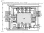
SYSTEM CONTROL IC100
R5F3650KBDFA
12
0 JL150 50
0
AUDIO-CLK 49
JL149
0 48
JL148
0 AUDIO-DATA 47
JL147
0 FLASH-MEMORY 46
JL146
HUB...
Service Manual - Page 26
...
JL405
2 RED_LED
3
JL406
3 BLUE_LED
1000p 50V
Q607 RT3TAAM-TP-1
0
0 Q607 - HCD-SH2000
5-11. Q604 LED DRIVER
3.2
C804 1000p 50V C809
23
24
25
MAIN
6 26
BOARD...
0.6 FB 5
C836 0.1
58 R806 7.5k
C837 3300p
22p 50V
R794 4.7k
C885
C884
10
10
16V
16V
IC600
OP-AMP
IC600
BA4558F
4.5
9
1 OUTPUT VCC 8
4.5
4.5
2 INPUT- SCHEMATIC DIAGRAM - OUTPUT 7
4.5
4.5
3 INPUT+ INPUT-...
Service Manual - Page 57

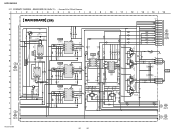
...
DECIMATION FILTERS
AUDIO INPUT PORT
RATE ESTIMATOR
AUDIO OUTPUT
PORT
BYPAS 9 IFMT0 10 IFMT1 11 IFMT2 12
RST 13 MUTE 14
CONTROL LOGIC
28 MODE2 27 MODE1 26 MODE0
25 BCKO 24 LRCKO 23 SDOUT
22 VDD 21 DGND
20 TDMI
19 OFMT0 18 OFMT1 17 OWL0 16 OWL1 15 RDY
HCD-SH2000
57
Service Manual - Page 61

...-OE
O MTK Vbus Output enable control pin
26
DAMP-CLK
O Clock to Digital Amp
27
/HUB-OC1
I USB Overcurrent Detection input port 1
28
/HUB-OC2
I USB...AUDIO-CLK
O Serial data transfer clock signal output to audio signal processor, R2A15216FP
50
NO-USE
O Unused
51
/LINE-MUTE
O Muting Control Switch for several hundreds msec and then change to LED Driver, R8A66166SP
BYTE
- HCD-SH2000...
Service Manual - Page 62
... terminal Unused Unused VACS level detection signal (A/D input) Key input terminal (A/D input) Unused Digital Amp Reset Pin Digital Amp Shutdown Protection Detect on Ground terminal (for A/D conversion) Jog dial pulse input from the MASTER VOLUME encoder..."H": LED on Amplifier Pin. "H": LED on Speaker RIGHT RED LED Control Pin. HCD-SH2000
Pin No. 52 53 54 55 56 57 58 59 60 61 62 63 64 65 ...
Service Manual - Page 64

HCD-SH2000
Pin No. 69 to 74
75 76 77 78 79 80 81 to 83 84 ... terminal Not used
I Audio data input from the system controller
O Communication initialization request acknowledge signal output to the system controller
- Power supply terminal (+3.3V)
O Component video (Y) signal output terminal Not used O Component video (Pb/Cb) signal output terminal Not used O Component video (Pr/Cr) signal...
Service Manual - Page 70

...
• CAPACITORS uF: μF
• COILS uH: μH
The components identified by reference number, please include the board name.
• ...HCD-SH2000
Ver. 1.1 AUDIO-IN BUTTON
BUTTON LED
SECTION 7 ELECTRICAL PARTS LIST
Note: • Due to standardization, replacements in
the parts list may have some difference from the parts specified in the diagrams or the components...
Similar Questions

My Sony Hcd-sh2000 Only Shows Standby, It Can't Switch On,even When I Used Remot
(Posted by ekereteu 1 year ago)


Speaker Wire Connector
looking for part number: 1-839-129-11 and 1-839-128-2
looking for part number: 1-839-129-11 and 1-839-128-2
(Posted by Crsj1981 2 years ago)

Sony Mhc-ec709ip Does Not Work Shows Protect
(Posted by dawa 9 years ago)