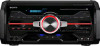
Sony HCD-SH2000 Support Question
Sony HCD-SH2000 Support Question
Find answers below for this question about Sony HCD-SH2000.Need a Sony HCD-SH2000 manual? We have 1 online manual for this item!
Question posted by Mikefoguetao on December 26th, 2022
How Can I Take Out On My Sony The Protect If I On It It Say Protect So What I Ca
The person who posted this question about this Sony product did not include a detailed explanation. Please use the "Request More Information" button to the right if more details would help you to answer this question.
Current Answers
Answer #1: Posted by SonuKumar on December 26th, 2022 6:55 PM
SonuKumar

Member since:
May 9th, 2021 Points: 16,621,300

Member since:
May 9th, 2021 Points: 16,621,300
https://youtu.be/3CabYmF_MT4
Protect/protector mode is activated to prevent damages to your receiver's internal components such as the power amps, circuits, transistors, etc. The possible culprits that would activate this mode, will be a power surge, a short in the circuitry, excessive heat, speakers issue, and more.
https://www.manualslib.com/manual/557525/Sony-Hcd-Sh2000.html
Please respond to my effort to provide you with the best possible solution by using the "Acceptable Solution" and/or the "Helpful" buttons when the answer has proven to be helpful.
Regards,
Sonu
Your search handyman for all e-support needs!!
Related Sony HCD-SH2000 Manual Pages
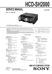
Service Manual - Page 1
...;, 1 kHz) Low channel 500 W + 500 W (per channel at a distance of Sony Corporation. • MPEG Layer-3 audio coding technology and patents licensed from Microsoft. speakers) (Approx.)
510 mm × 235 mm × 420 mm Mass (excl.
HCD-SH2000
SERVICE MANUAL
E Model
Ver. 1.1 2011.09
• HCD-SH2000 is the tuner, USB, CD and amplifier section...
Service Manual - Page 2
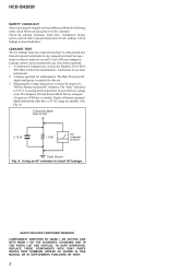
...these instruments. 2.
REPLACE THESE COMPONENTS WITH SONY PARTS WHOSE PART NUMBERS APPEAR AS SHOWN IN THIS MANUAL OR IN SUPPLEMENTS PUBLISHED BY SONY.
2 HCD-SH2000
SAFETY CHECK-OUT After correcting the... is 0.75 V, so analog meters must not exceed 0.5 mA (500 microamperes). SAFETY-RELATED COMPONENT WARNING! Leakage current can be measured by means of three methods. 1. A. The "limit"...
Service Manual - Page 3
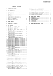
...40 5-26. DAMP Board (3/4 41 5-27. DISPLAY Board 44 5-30. Schematic Diagram - AUDIO-IN Board 51 5-37. Printed Wiring Boards - MIC Board 52 5-39. Front Panel Section...
- DAMP Board (Conductor Side 38 5-24. VOLUME Board 45 5-31. HCD-SH2000
TABLE OF CONTENTS
1. DAMP Board (Component Side 37 5-23. Schematic Diagram - Schematic Diagram - Schematic Diagram - Printed...
Service Manual - Page 4
... conforms to ISO 9660 2) Level 1/Level 2, Joliet (in expansion format), or Multi Session 3)
1) MP3 (MPEG 1 Audio Layer 3) is included in the repair parts.
HCD-SH2000
Ver. 1.1
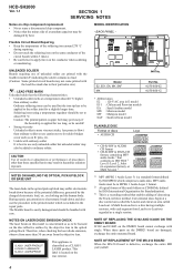
SECTION 1 SERVICING NOTES
Notes on chip component replacement • Never reuse a disconnected chip component. • Notice that the minus side of a tantalum capacitor may be set to about 40...
Service Manual - Page 5
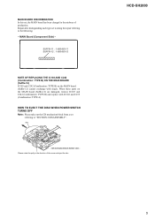
MAIN Board (Component Side) - When these parts on the MAIN board (Suffix-12) cannot exchange with IC102 and ... B) on the MAIN board (Suffix-12) are damaged, remove IC103 and C242 (Combination: TYPE B) and replace with single.
HCD-SH2000
5 Please rotate the pully in the midway of the arrow and eject the disc.
CD mechanism block bottom view - Repair after distinguishing...
Service Manual - Page 14
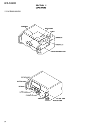
HCD-SH2000
• Circuit Boards Location
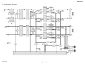
SECTION 5 DIAGRAMS
DAMP board
MS-214 board TUNER MAIN board
DMB21 board SWITCHING REGULATOR
DISPLAY board BUTTON board
MIC board
BUTTON LED board VOLUME LED board USB board
VOLUME board AUDIO-IN board
14
Service Manual - Page 16
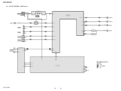
MAIN Section - SIGNAL PATH
: AUDIO : TUNER (FM/AM) : MIC
HCD-SH2000
16
16 J1300 MIC IN
A (Page 15)
L-OUT
J1200
TV R-CH
J1201
PC
GAME AUDIO IN
DVD/SAT AUDIO IN
J500 L R L R
R-CH R-CH R-CH
IC1300 MIC AMP
5
7
3
1
RV1300
MIC LEVEL MIN MAX
IC501 OP AMP
5
7
46 ...XC-IN 10 XC-OUT 11
X113 8MHz
X110 32.768kHz
R-ch is omitted due to same as L-ch.
HCD-SH2000
5-2. BLOCK DIAGRAM -
Service Manual - Page 17
...
5 INPUT+ OUTPUT 7
C Lch
(Page 16)
R-CH
3 INPUT+ OUTPUT 1
MUTE Q600
OP AMP IC600
5 INPUT+ OUTPUT 7
SIGNAL PATH
: AUDIO
MUTE Q207
51
/LINE-MUTE DAMP-CLK /DAMP-RESET
NO USE /SD-SLOW RESONANCE
D1403 D1435
HCD-SH2000
LOW SPEAKER IMPEDANCE USE 4ȍ
2 INA- AMP Section - 5-3. AOUT 1
PREAMP IC1404
5 INB+ BOUT 7
BUFFER IC1411
5
7
3
1
INA+ INB...
Service Manual - Page 19

... model
HCD-SH2000
19
19
HCD-SH2000
Ver....AUDIO (DIGITAL)
• Abbreviation E2 : 120 V AC area in μF unless otherwise noted. (p: pF)
50 WV or less are not indicated except for electrolytics and tantalums. • All resistors are omitted.
• Note for Printed Wiring Boards and Schematic Diagrams
Note on Printed Wiring Board:
• X : parts extracted from the component...
Service Manual - Page 20

...Page 47)
VOLUME
A BOARD CN1000 (Page 45)
AUDIO-IN
H BOARD NO1200 (Page 51)
11 (11)
CN704
CN705
(CHASSIS)
G
DAMP BOARD CN1400 (Page 37)
B
DAMP BOARD CN1401 (Page 37)
J
HCD-SH2000
20
20
Note: Refer to the servicing notes ... 1
R158
CN100
14
1-883-863- PRINTED WIRING BOARDS -
HCD-SH2000
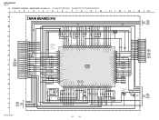
5-5. MAIN BOARD (Component Side) (Suffix-11) - • See page 14 for how to distinguish SUFFIX-11 ...
Service Manual - Page 22

... CN1000 (Page 45)
AUDIO-IN
H BOARD NO1200 (Page 51)
12 (12)
(CHASSIS)
G
DAMP BOARD CN1400 (Page 37)
B
DAMP BOARD CN1401 (Page 37)
J
HCD-SH2000
Note 1: Refer to the servicing notes "MAIN BOARD DISCRIMINATION" (page 5) for Circuit Boards Location. • : Uses unleaded solder.
1
2
3
4
5
6
7
8
9
10
11
12
13
14
15
A
MAIN BOARD (Component side)
B
TUNER
J BOARD...
Service Manual - Page 24
...AVCC
JL200 1.3 100
IC100
SYSTEM CONTROL IC100
R5F3650KBDFA
12
0 JL150 50
0
AUDIO-CLK 49
JL149
0 48
JL148
0 AUDIO-DATA 47
JL147
0 FLASH-MEMORY 46
JL146
HUB-VBUS-DET 45 3.2 ...R259
4.7k
10k
14
13.4
12.7
LED SWITCH
Q205
2SB1690TL
13.4
MAIN
3 BOARD (3/4) (Page 26)
12
58
13
HCD-SH2000
24
24 HCD-SH2000
Ver. 1.1
5-9. EA 4.7k - E2, E51, MX
*2 R290 330 - E2, E51, MX 0 - SAF, ...
Service Manual - Page 27

...C561 820p 50V
DSP-CLK 2 DSP-DATA 1
JL732 R745 JL731 R744
0 78 0 77
HCD-SH2000
27
27 5-12. OUTPUT INPUT+ INPUTGND INPUT+
IC503 BPF BA4558F
BB1L BB2L OUTL AGCOUTL AGCC... SWOUT CLK DATA AGCOUTR OUTR BB2R BB1R VOLINR TONEOUTR
15k
GAME IN-L
R739 27k
GAME
AUDIO IN
WHT
RED
L
R
C
D
MAIN
3
2 BOARD
1
(1/4)
2
(Page 24)
IC503
C694
R696
R698
...
Service Manual - Page 28

...JL200 1.3 100
IC100
SYSTEM CONTROL IC100
R5F3650KBDFA
12
0 JL150 50
0
AUDIO-CLK 49
JL149
0 JL148 48
0 AUDIO-DATA 47
JL147
0 FLASH-MEMORY 46
JL146
HUB-VBUS-DET 45 3.2...
R259
4.7k
10k
14
13.4
12.7
LED SWITCH
Q205
2SB1690TL
13.4
MAIN
3 BOARD (3/4) (Page 30)
12
58
13
HCD-SH2000
28
28 SAF 1k - MAIN BOARD (1/4) (Suffix 12) - • See page 53 for Waveforms. • ...
Service Manual - Page 31

... 33k
R743 27k
R867 0
JL602 JL603
C726 0.47
WHT J500
DVD/SAT
AUDIO IN
RED
L
R
33k 0.1
OUTPUT VCC INPUT- MAIN BOARD (4/4) (Suffix 12) - • See page 54 for IC Block Diagrams.
1
2
3
4
5
6
7
8
HCD-SH2000
9
10
11
12
13
14
15
A
MAIN BOARD (4/4)
29
R857
...1000p
R547 2.7k
C561 820p 50V
DSP-CLK 2 DSP-DATA 1
JL732 R745 JL731 R744
0 78 0 77
HCD-SH2000
31
31
Service Manual - Page 59
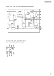
...INPUT A+ INPUT V- INPUT B+ INPUT
8
7
6
5
- +
- +
1
2
3
4
A OUTPUT A- HCD-SH2000
IC1406, IC1407, IC1408, IC1409 IRS2092STRPBF (DAMP BOARD (2/4))
VAA 1 GND 2
IN- 3 COMP 4
6V
6V
FLOATING INPUT...
UV DETECT
20.4V
16 CSH 15 VB
14 HO
13 VS 12 VCC
CSD 5
CHARGE/ DISCHARGE
VSS 6
PROTECTION CONTROL
HV LEVEL SHIFT
HV LEVEL SHIFT
DEAD TIME
SD DT
11 LO
20.4V
LOW SIDE CS
10 COM 9...
Service Manual - Page 62
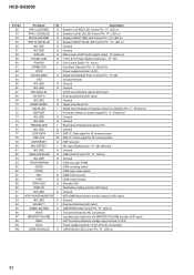
HCD-SH2000
Pin No. 52 53 54 55 56 57 58 59 60 61 62 63 64 65 66 67 68 69 70 71...7V Power Switch Control pin. "H": LED on Unused Unused Main power on/off control signal output "H":power on Speaker Left BLUE LED Control Pin. "L": Protect on' Protection Detect on
62 "H": LED on power supply Pin. USBB-LED-BLUE
O
Description Speaker Left RED LED Control Pin. "H": 13V Fan Control Switch "H": ...
Service Manual - Page 64

...O Audio data output to the D/A converter
- Audio D/A...Component video (Pr/Cr) signal output terminal Not used
- Power supply terminal (+1.8V)
- Ground terminal
O Bank address signal output to the SD-RAM
O Address signal output to the coil/motor driver (for USB) - Not used - Ground terminal
O Composite video signal output terminal Not used - Not used
- HCD-SH2000...
RWE# CAS# RAS#...
Service Manual - Page 65
...-3
#2
7-685-646-71 SCREW +BVTP 3X8 TYPE2 IT-3
Remark
65 MAIN SECTION
#1
10
HCD-SH2000
Ver. 1.1
The components identified by mark 0 or dotted line with mark 0 are seldom required for safety.....6 (3CR) HANDLE, COVER B
6
4-291-803-01 COVER, HOLE
7
4-277-991-01 PLATE, SONY
Remark
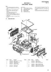
Ref. SECTION 6 EXPLODED VIEWS
Note: • The mechanical parts with no reference
number in E ...
Service Manual - Page 70

...PC. . , uPD. . : μPD. .
• CAPACITORS uF: μF
• COILS uH: μH
The components identified by reference number, please include the board name.
• Abbreviation E2 : 120V AC area in ohms. METAL: Metal...for routine service. Description
AUDIO-IN BOARD
Remark
Ref.
METAL OXIDE: Metal oxide-film resistor. HCD-SH2000
Ver. 1.1 AUDIO-IN BUTTON
BUTTON LED
...
Similar Questions


Speaker Wire Connector
looking for part number: 1-839-129-11 and 1-839-128-2
looking for part number: 1-839-129-11 and 1-839-128-2
(Posted by Crsj1981 2 years ago)


How To Remove Push Power Protect To My Sony Hcd-dp1000d?
(Posted by samaddj 11 years ago)

How To Remove Push Power Protect To My Sony Hcd-dp1000d?
how to remove push power protect to my sony HCD-DP1000D?
how to remove push power protect to my sony HCD-DP1000D?
(Posted by chad111207 11 years ago)