
Sharp CD-E55 Support Question
Sharp CD-E55 Support Question
Find answers below for this question about Sharp CD-E55.Need a Sharp CD-E55 manual? We have 1 online manual for this item!
Current Answers
Answer #1: Posted by BusterDoogen on November 22nd, 2016 2:35 PM
BusterDoogen

Member since:
October 30th, 2011 Points: 28,565,407

Member since:
October 30th, 2011 Points: 28,565,407
This normally is due to a speaker wiring failure. I suggest you check the speaker wiring at the receiver & the speakers for fraying or loose connection.
I hope this is helpful to you!
Please respond to my effort to provide you with the best possible solution by using the "Acceptable Solution" and/or the "Helpful" buttons when the answer has proven to be helpful. Please feel free to submit further info for your question, if a solution was not provided. I appreciate the opportunity to serve you!
Related Sharp CD-E55 Manual Pages
Service Manual - Page 1
... NOTES (FOR U.S.A.
MODEL CD-E55
CD-E55 Mini Component System consisting of CD-E500 (main unit) and CP-E500 (speaker system). ONLY)
SHARP CORPORATION
This document has been published to be used for after sales service only. ONLY) ...2 SPECIFICATIONS ...2 NAMES OF PARTS ...3 DISASSEMBLY ...5 REMOVING AND REINSTALLING THE MAIN PARTS ...7 ADJUSTMENT ...10 TEST MODE ...11 NOTES ON SCHEMATIC...
Service Manual - Page 2
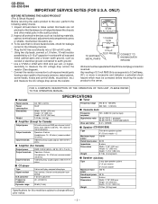
...are subject to all protective devices such as ...harmonic distortion
Speakers: 8 ohms
Headphones: 16 - 50 ohms (recommended: 32 ohms)
Video/Auxiliary (audio signal): 500 mV/47 k ohms
s Amplifier (For Canada)
Output power Output terminals
Input terminals
...OPERATION OF THIS UNIT, PLEASE REFER TO THE OPERATION MANUAL. CD-E500 CD-E55/E44
IMPORTANT SERVICE NOTES (FOR U.S.A.
VTVM AC SCALE
1.5 ...
Service Manual - Page 3
..., Tape 2 Fast Forward,
23
Tuner Preset Up Button
24 25
CD-E500/E55
12
3
10 11
1
2 3
1 2 1
45 67 8 9
12 13
4 5
2
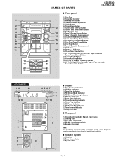
s Display
1. Tape Play Indicator 4. AC Power Input Jack 4. Equalizer Mode Select Button
15
13. FM Stereo Receiving Indicator 6. Video/Auxiliary (Audio Signal) Input Jacks 2. CD Play or Repeat, Tape Play Button
25. Tape Record Indicator...
Service Manual - Page 4
.../Auxiliary Button
8
14. CD-E500 CD-E55/E44
CD-E44
12
3
10 11
1
2 3
1
2
2
3
45 67 8 9
12 13
4 5
4
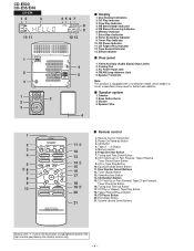
s Display
1. CD Button
4. Tape 2 Record Pause Button
19. CD Repeat Play Indicator 12. Video/Auxiliary (Audio Signal) Input Jacks 2. Timer Recording Indicator 9. Tape (1 2) Button
3
12
5. Equalizer Mode Select Button
6 7
16
11. CD Play Indicator 3. Tweeter...
Service Manual - Page 5
...protect the optical pickup from the wall
outlet before disassembling. 4. After removing the connector for the optical pickup from the
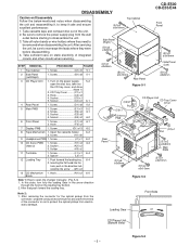
connector, wrap the conductive aluminium foil around the front end of the connector so as to open the disc tray, take out the CD...open the changer manually. (Fig. 5-3) 1. DISASSEMBLY
CD-E500 CD-E55/E44
Caution on static electricity of integrated circuits and...
Service Manual - Page 9
...to remove the up/down loading motor (See Figs. 9-2)
1. Remove the screws (A1) x 2 pcs. 2.
CD-E500 CD-E55/E44
Loading Tray
(A1)x2 ø2.4x3mm
(A2)x1
T/T Motor PWB
(A3)x2 ø3x10mm
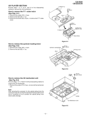
Loading Tray ... CD PLAYER SECTION
Perform steps 1, 2, 3, 10,11, and 12 of the disassembly method to remove the T/T rotate
motor. Remove the screws (A3) x 2 pcs., to remove the CD mechanism. How to protect ...
Service Manual - Page 10
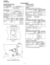
...Antenna *2. Input: Antenna
Output: TP301
Figure 10-1
• FM Mute Level (FM ST MODE) Signal generator: 1 kHz, 40 kHz dev., FM modulated
MAIN PWB
TP302
T351 AM IF... Coverage
AM Tracking 990 kHz
*1. former T304
fully counter- Input: Antenna Output: TP301 *2. CD-E500 CD-E55/E44
ADJUSTMENT
MECHANISM SECTION
TUNER SECTION
• Driving Force Check Torque Meter
Play: DM-300
...
Service Manual - Page 11
... turned off to
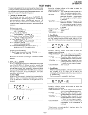
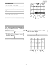
shift to the ordinary standby mode. TEST MODE
CD-E500 CD-E55/E44
The test mode applied to this microcomputer has three modes, namely the ordinary test mode for adjustment or measurement, the aging test mode, and the self-diagnosis test mode for the following buttons to be pressed. Test mode and power turned off to
shift to...
Service Manual - Page 12
...Mode When the CD...protect the memory of test mode... 4 Mode The CLV...mode ...standby mode. Test mode and...mode.
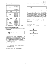
• The TUNER TEST02 mode...CD PLAY.
- 12 -
When the tuner test mode is executed in the destinations when the test mode...mode ...mode The tuner test mode...mode is pressed. Even if playback reaches the outermost periphery of ordinary CD playback.
3. Tuner Test Mode...mode. Test mode and power...
Service Manual - Page 13
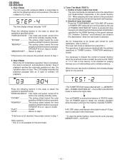
... 1:00, the timer to ON time 1:05, the function to CD, and volume to CD, respectively. The button operations in the test mode are lighted. After completion of fade-in, the fadeout is executed ...turned off (after WAIT 1 sec), and the mode is Volume -14 dB (STEP23), FLAT AND X-BASS ON, and start-up function to STEP 12, respectively.
CD-E500 CD-E55/E44
5. After completion of one second, and...
Service Manual - Page 14
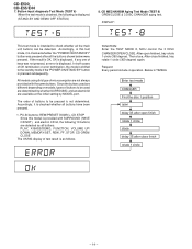
... is displayed. (STAND-BY AND DEMO OFF STATUS)
8.
The order of OK termination or error termination, the mode is shifted to be pressed is pressed subsequently. Request: Every period include 4 operation. CD-E500 CD-E55/E44
7. CD MECHANISM Aging Test Mode (TEST 8) OPEN/CLOSE & 3 DISC CHANGER aging test. In both cases of buttons to the standby...
Service Manual - Page 17
...Hz
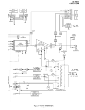
FROM CNS901 DISPLAY SECTION
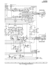
Figure 17 BLOCK DIAGRAM (2/4) - 17 - CD-E500 CD-E55/E44
FROM DISPLAY SECTION
CNS102
FROM DISPLAY SECTION
CNS202
202 54321
FROM CD SECTION
CNS204
CNP204 123456
CNP102
CD_+B
+B4
1
MUTE
2
SIGAL_LVL
3...
TAPE L 10 R 15
TUNER L 11 R 14
CD L 12 R 13
DI 1
CE 2
IC601
CL 24
LC75341M
21 R
AUDIO PROCESSOR 4 L
7 8 17 18 3 23
+B2
IC101 STK40207 L 15 POWER AMP.
Service Manual - Page 25
_
CD-E500 CD-E55/E44
CNP601 D604 1N4148 D605 1N4148
SO601 VIDEO/AUX IN
O MAIN PWB(2/3) APE SECTION P23 12 - B
8 17 16 15 14 13 12
CNS205 FROM CD SERVO PWB P27 11 - R102 1K
R101 1K
-VCC +VE2 -VE2 PRE -VCC GND NF2 IN2
+VCC...
R606 1K R608 1K R628 1K C607 4.7/50
R624 12K R625 12K
CD R TUN R TAPE R
C606 10/16
R604 1K
IC601 LC75341M
AUDIO PROCESSOR
R1 L1 R2 L2 R3 L3 R4 L4 RSL0 LSL0 RIN LIN...
Service Manual - Page 39
...=200 mV DC 10:1
T
CH2=500 mV DC 10:1
1 IC401 21
T
FDO
2
CD-E500 CD-E55/E44
1999/04/07 09:51:15 500 ms/div (500 ms/div)
NORM:20 kS/s...
TDO
2 IC401 20 3
=Filter= Smoothing : ON BW : FULL
=Offset=
CH1 : 0.000 V
CH2 :
0.0 V
CH3 : 0.000 V
CH4 : 0.00 V
CH1 v/DIV 500 mV
=Record Length= Main : 100 K Zoom : 2 K
=Trigger=
Mode...
Service Manual - Page 41
...CH1=500 mV DC 10:1
T
FDO
1
CH3=500 mV DC 10:1
CD-E500 CD-E55/E44
500 ms/div (500 ms/div) NORM:20 kS/s
No 1. Is...: 0.00 V
CH1 v/DIV 500 mV
=Record Length= Main : 100 K Zoom : 2 K
=Trigger=
Mode : AUTO
Type : EDGE CH1
Delay :
0.0 ns
Hold off :
0.2 µs
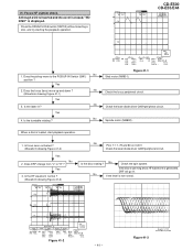
Figure 41-2
- 41 -
Yes
2. Although a CD is inserted and the cover is closed, "NO DISC" is not normal.
500 ms/div (500 ms/div...
Service Manual - Page 42
... CH3 : 0.00 V CH4 : 0.00 V
=Record Length= Main : 100 K Zoom : 2 K
=Trigger=
Mode : NORMAL
Type : EDGE CH2
Delay :
2.924 ms
Hold off :
0.2 µs
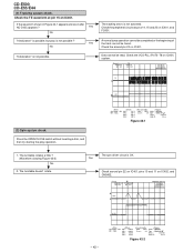
Figure 42-1
1. If the ...Mode : NORMAL
Type : EDGE CH1
Delay :
2.924 ms
Hold off :
0.2 µs
Figure 42-2 Check the VCO-PLL (Pin73~78 on IC401. The turntable rotates a little ? (Waveform drawing Figure 42-2) No
2. CD-E500 CD-E55...
Service Manual - Page 43
...impossible. Stopped CH1=500 mV DC 10:1
PDO1
3
CD-E500 CD-E55/E44
CH3=1 V DC 10:1
1999/04/05 17:...33:17
CH4=1 V DC 10:1
500 ms/div (500 ms/div)
NORM:20 kS/s
4
PDO2
T
FDO
1
=Filter= Smoothing : ON BW : FULL
=Offset=
CH1 : 0.000 V
CH2 :
0.0 V
CH3 : 0.00 V
CH4 : 0.00 V
CH1 v/DIV 500 mV
=Record Length= Main : 100 K Zoom : 2 K
=Trigger=
Mode...
Service Manual - Page 44
...signal detection output terminal. EFMIN
Input
- CD-E500 CD-E55/E44
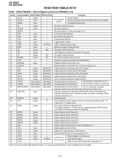
FUNCTION TABLE OF IC
IC401 VHiLC78646E-1: ...Servo/Signal Control (LC78646E) (1/2)
Pin No. 1 2 3 4
Terminal Name Input/Output Setting in EFM and the
sync signal of internal generation are set them as input terminals and connect
27*
SBCK/CONT6 Input/Output Input Mode...
Service Manual - Page 47
... CD-E55/E44
Function
Input signal pin.
Data transfer enabled at "H" level. Bass band filter comprisingcapacitor
and resistor connection pin.
22
Treble band filter comprising capacitor and resistor connection pin. Bass band filter comprisingcapacitor and resistor connection pin.
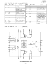
Chip enable pin. IC601 VHiLC75341M-1: Audio Processor (LC75341M)
LSEL0 LIN LTRE LBASS LOUT
L4 9 CD L3...
Service Manual - Page 51
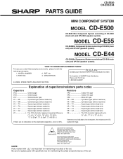
...:POUR ASSURER UNE LONGUE PROTECTION CONTRE UN INCENDIE, REMPLACER SEULEMENT PAR UN FUSIBLE DE TYPE F901,902 5A, 125V/ F903 1.6A, 125V FUSE
NOTE: Parts marked with specified ones for maintaining the safety of CD-E500 (main unit) and CP-E500 (speaker system). MODEL CD-E55
CD-E55 Mini Component System consisting of CD-E44 (main unit) and...
Similar Questions


Is It Possible To Get A New Power Cord That Connects The Cd Player To An Outlet?
(Posted by Roxannesemonchik 9 years ago)

How Do I Get The Sound Bar Out Of Protection Mode.
will not turn on red light flashing states that it is on protection mode in manuel
will not turn on red light flashing states that it is on protection mode in manuel
(Posted by tgaalp 10 years ago)

Looking For An Antenna For My Sharp Cd-e55 Mini Component System
I need a replacement antenna for my CD-E55 Mini Component System.
I need a replacement antenna for my CD-E55 Mini Component System.
(Posted by hermanmoore01 10 years ago)
