
Sharp CD-E55 Support Question
Sharp CD-E55 Support Question
Find answers below for this question about Sharp CD-E55.Need a Sharp CD-E55 manual? We have 1 online manual for this item!
Question posted by hermanmoore01 on July 22nd, 2013
Looking For An Antenna For My Sharp Cd-e55 Mini Component System
I need a replacement antenna for my CD-E55 Mini Component System.
Current Answers
Related Sharp CD-E55 Manual Pages
Service Manual - Page 1
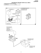
... FL DISPLAY ...50 REPLACEMENT PARTS LIST/EXPLODED VIEW PACKING OF THE SET (FOR U.S.A. ONLY)
SHARP CORPORATION
This document has been published to those specified be used . CONTENTS
Page IMPORTANT SERVICE NOTES (FOR U.S.A. The contents are subject to change without notice. CD-E500 CD-E55/E44
SERVICE MANUAL
No. MODEL CD-E55
CD-E55 Mini Component System consisting of CD-E500 (main unit...
Service Manual - Page 2
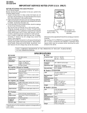
...dB (TAPE 1, playback) 50 dB (TAPE 2, recording/playback) 0.3 % (WRMS)
s Speaker (CD-E500/E55)
Type
Maximum input power Rated input power Impedance Dimensions
Weight
Twin-drive speaker system 4" (10 cm)...and indicates a potential shock hazard which must be corrected before returning the audio product to the chassis (antenna, metal cabinet, screw heads, knobs and control shafts, escutcheon, etc...
Service Manual - Page 3
...18. CD or Tape Stop Button
21. Tape Record Indicator 13. Video/Auxiliary (Audio Signal) Input Jacks 2. Timer/Sleep Button
12
7. Headphone Jack
13
10. CD Track...8 9 10 11
18 19 20 21
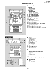
NAMES OF PARTS
CD-E500 CD-E55/E44
s Front panel
1.
Bass Reflex Ducts 3. CD Play or Repeat, Tape Play Button
25. FM/AM Loop Antenna Jack 5. Tape Play Indicator 4. Speaker Wire
3
- 3 ...
Service Manual - Page 4
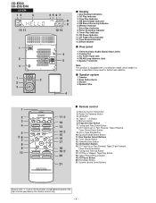
...Tape 2 Record Pause Button
19. FM/AM Loop Antenna Jack 5. Remote Control Transmitter
2. CD Random Button
15. CD Pause Button
20. AC Power Input Jack 4. CD-E500 CD-E55/E44
CD-E44
12
3
10 11
1
2 3
1... Indicator 8. Timer Play Indicator 10. CD Repeat Play Indicator 12. Tape Record Indicator 13. Video/Auxiliary (Audio Signal) Input Jacks 2. Cooling Fan ...
Service Manual - Page 5
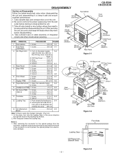
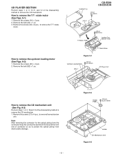
...push foward the loading tray. Screw J1) x1 6-2
10 CD Servo PWB 1. DISASSEMBLY
CD-E500 CD-E55/E44
Caution on the power supply, .. 5-2 open the ...changer manually. (Fig. 5-3) 1. After servicing the unit, be sure to rearrange the leads where they need to keep it safe and ensure excellent performance: 1. Screw B1) x8 5-1
3 CD...
Service Manual - Page 6
...
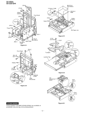
(H1)x8 ø3x8mm
Open
(J1)x1 ø2.5x10mm
Headphones PWB Holder PWB
Figure 6-2
Cassette Holder
Tape Mechanism
Figure 6-4
CD Mechanism Block
Hook (N1)x1
Pull
CP-E500/E55/E44 These speakers CP-E500,CP-E55,CP-E44 are available in assembles only and may not be disassembled.
- 6 -
Figure 6-5
Hook (N1)x1
Pull
Service Manual - Page 7
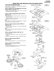
...., to remove the belt (TAPE 1) (See Fig. 7-5)
1. Note: After replacing the heads and performing the azimuth adjustment, be removed. Remove the screws (D2) x 3 pcs., to remove the motor.
(B1)x2 ø2x8mm
Erase Head Record/ Playback Head Figure 7-2 TAPE 1 TAPE 2
CD-E500 CD-E55/E44
TAPE 1
TAPE 2
How to remove the motor
bracket. 3.
Remove...
Service Manual - Page 8
...., with a new one. Remove the stop washer is deformed or damaged, replace it with a small precision screwdriver to reinstall the parts
Install each part in the reverse order of the removal with care.
Remove the screw (J2) x 1 pc. 3.
CD-E500 CD-E55/E44 How to remove the tape mechanism PWB.
2.
How to extract the...
Service Manual - Page 9
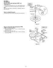
Remove the screws (A1) x 2 pcs. 2.
Remove the screws (C1) x 4 pcs., to remove the T/T rotate motor (See Figs. 9-1)
1. Remove the screws (B1) x 2 pcs. 2.
CD-E500 CD-E55/E44
Loading Tray
(A1)x2 ø2.4x3mm
(A2)x1
T/T Motor PWB
(A3)x2 ø3x10mm
Loading Tray (Bottom View)
T/T Rotate Motor
Figure 9-1
Up/Down Loading ...
Service Manual - Page 10
CD-E500 CD-E55/E44
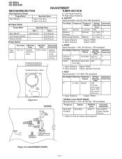
ADJUSTMENT
MECHANISM SECTION
TUNER SECTION
• Driving Force Check Torque Meter
Play: DM... Terminal (Load resistance: 8 ohms)
Test Stage Frequency Frequency Display
Setting/ Instrument Adjusting Connection
Point
FM Band - Input: Antenna Output: Speaker Terminal
• FM IF Signal generator: 10.7 MHz, FM modulated
Test Stage Frequency Frequency Display
Setting/ ...
Service Manual - Page 11
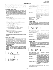
...TEST 2
TUNER(BAND) + VOLUME UP 3. If PICKUP IN is on, input is executed. Then CD initialization operation flow proceeds up
Press the following buttons in this state to be taken in this case.... Mode] 1.
If focus has been taken, shift to step 4 is invalid. TEST MODE
CD-E500 CD-E55/E44
The test mode applied to this microcomputer has three modes, namely the ordinary test mode ...
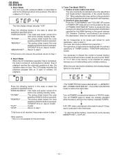
Service Manual - Page 12
...
*If the focus is pressed. If AC OFF state is maintained in the preset memory CH. CD-E500 CD-E55/E44
4. "MEMORY/SET" ...... Return to obtain the operations specified below . Tuner Test Mode (... disc, the operation does not stop. Even if playback reaches the outermost periphery of ordinary CD playback.
3. The LCD display indicates the playback passage time as in the memory (besides ...
Service Manual - Page 13
...fade-in (when playback is started) is executed at a rate of one step for 1 sec.
CD-E500 CD-E55/E44
5.
After completion of even segments
- 13 -
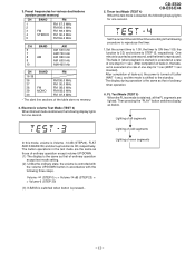
3.Preset frequencies for various destinations (random preset...Volume -14 dB (STEP23), FLAT AND X-BASS ON, and start-up function to CD, respectively. The display during operation is the same as that of ordinary operation
except test...
Service Manual - Page 14
CD-E500 CD-E55/E44
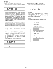
7. DISPLAY:
This test mode is as all the main unit buttons can be used are detected as... the buttons used are determined by whether SURROUND, and an electric lid are not always provided with SURROUND (HAVE OR NOT), and electric CD lid, the following is checked whether all the buttons shown below were pressed. Then close, After close finish
rotate 1 circle
- 14 ...
Service Manual - Page 16
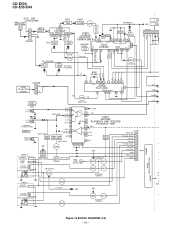
CD-E500 CD-E55/E44
FM ANTENNA AM LOOP ANTENNA
B.P.F
3
BF301
2 1
FM IF
T304
6 IC301 1 TA7358AP FM FRONT END 9 234 5 7 8
FM OSC
CNP301
FM RF L302
L303
OSC BUFF...
X352
VT
4.5 MHz
SD FM ST
CE CL DO DI
FRO
DISPLAY
+B2
CNS
CNP202 765432
FM IN AM IN
DO
CL
DI
CE
FROM CD SECTION
CNS205
CNP205 1L
2 3R
20 1 22 16 15 11 3 4 5 6
OSC IC302
LC72131 PLL(TUNER)
17
MUTE
FM/AM MO/ST
...
Service Manual - Page 51
....
1. Be sure to order.
3. "HOW TO ORDER REPLACEMENT PARTS"
To have your nearest SHARP Parts Distributor to replace parts with " " are important for maintaining the safety and... wire) VC J ..
MODEL CD-E55
CD-E55 Mini Component System consisting of CD-E44 (main unit) and CP-E44 (speaker system). CAUTION:FOR CONTINUED PROTECTION AGAINST FIRE HAZARD, REPLACE ONLY WITH SAME TYPE F901,902...
Service Manual - Page 56
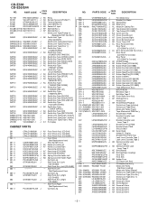
... J
SO601
QSOCJ0003SJZZ J
1 SO901
QSOCA0214AWZZ J
SOL801(219-5) 9GD19212118
J
SOL802(219-5) 9GD19212118
J
SW1
----
Front Panel
(Not Replacement Item) Gear,Damper Ass'y AF Holder,Cassette,Left AF Holder,Cassette,Right Panel,Amp [CD-E44] AF Panel,Amp [CD-E500] AF Panel,Amp [CD-E55] AB Spring,Cassette Holder,Left AD Spring,Cassette Holder,Right Cushion,Leg Side Panel...
Service Manual - Page 57
...E55 For U.S.A.]
TINSZ0192SJZZ J
Operation Manual
[CD-E500/E55 For Canada]
RRMCG0063SJSA J AP Remote Control
P.W.B. Main
1 PWB-B1~4 DCEKNV280SJ03 J -- CD Servo
PWB-F
----
-- Power/Display/Headphones/
Terminal(Combined Ass'y)
PWB-C
DCEKSV280SJ03 J -- Switch
(Supplied at REF No.238,
Changer Unit)
PWB-G
----
-- ASSEMBLY (Not Replacement Item)
PWB-A
DCEKKV280SJ03 J -- CD-E500 CD-E55...
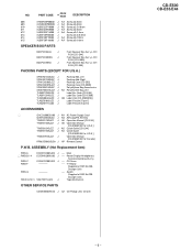
Service Manual - Page 59
..., Feature Tape2
TLABZ0106SJZZ
Label, Feature Tape1
A
AC Power Supply Cord AM/FM Loop Antenna Quick Guide Operation Manual Remote Control
SSAKA0014SJZZ Polyethylene Bag, Accessories
CD-E500 CD-E55/E44
B
B
FRONT
A
SPAKC0283SJZZ (CD-E500) SPAKC0282SJZZ (CD-E55) SPAKC0274SJZZ (CD-E44) Packing Case
- 8 - TLABR1299SJZZ (CD-E500) TLABR1298SJZZ (CD-E55)
TLABR1300SJZZ (CD-E44) Label ,Bar Code
Service Manual - Page 60
CD-E500 CD-E55/E44
COPYRIGHT © 2003 BY SHARP CORPORATION
ALL RIGHTS RESERVED. SHARP CORPORATION AV Systems Group Audio Systems Division Higashihiroshima, Hiroshima 739-0192, Japan
Printed in any form or by any means, electronic, mechanical, photocopying, recording, or otherwise, without prior written permission ...
Similar Questions

Can The Sharp Cd-dh899n Mini Component System Be Adaptable To Bluetooth?
I was given a Sharp CD-DH899N Mini Component System. It has never been out of the box so I am wonder...
I was given a Sharp CD-DH899N Mini Component System. It has never been out of the box so I am wonder...
(Posted by scpenrod48 8 months ago)


Sharp Mini Component System Model# Cd-ba3100
Everytime I plug in my system ER-AP00 keeps coming up I already removed the wiring for the speakers ...
Everytime I plug in my system ER-AP00 keeps coming up I already removed the wiring for the speakers ...
(Posted by Elbad56 7 years ago)

Is It Possible To Get A New Power Cord That Connects The Cd Player To An Outlet?
(Posted by Roxannesemonchik 9 years ago)

Looking For Radio Antenna For Sharp Stereo Component System, Model No. Cd-e66
(Posted by beeda603 10 years ago)