LiftMaster SL930 Support Question
LiftMaster SL930 Support Question
Find answers below for this question about LiftMaster SL930.Need a LiftMaster SL930 manual? We have 2 online manuals for this item!
Question posted by djzrna on January 4th, 2012
Operational Instructions
We have recently had one of these installed and have no instructions on how to get this opener to work the maual on here doesnt seem to have the info I need..
Current Answers
Related LiftMaster SL930 Manual Pages
SL930 Addendum Manual - Page 1
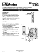
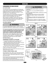
...instructions with the owner's manual. WIRING
CONTROL WIRING
BATTERY BACKUP
If the gate operator is not part of the standard wiring (Figure 4).
1. Disconnect power to terminal 15 of the control board.
5. Connect a green wire from terminal 2 to gate operator...board to the 14 screw terminal on control board.)
INSTALLATION
If the gate operator did not come from terminals 13 and 14 and ...
SL930 Manual - Page 1

MOMDEOLDSELL9S3L093D0C BB
HEAVY DUTY COMMERCIAL SLIDE GATE OPERATOR
2 YEAR WARRANTY
Serial located on electrical box cover) Installation Date
MODEL SL930 IS FOR VEHICULAR PASSAGE GATES ONLY AND IS NOT INTENDED FOR PEDESTRIAN PASSAGE GATE USE
SL930 Manual - Page 2
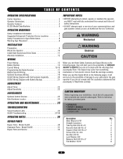
...INVENTORY
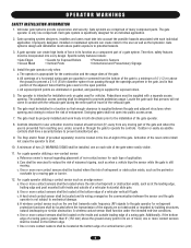
AVERTISSEMENT Before beginning your installation, check that all safety instructions.
• DO NOT attempt repair or service of SERIOUS INJURY or DEATH if you do not comply with :
OPERATOR NOTES 29 REPAIR PARTS
Repair Parts - OPERATION AND MAINTENANCE 25
TROUBLESHOOTING
Visual Feedback LEDs 26 SL930 Troubleshooting 27-28
• OPERATOR • OWNER'S MANUAL • HARDWARE...
SL930 Manual - Page 3
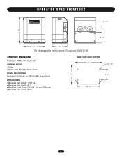
..."
8-1/2"
17"
12"
The following models are not currently ETL approved: SL930-DC-BB
OPERATOR DIMENSIONS
Height: 21" Width: 17" Depth: 12"
SHIPPING WEIGHT 170 lbs. rise over 20 ft. run) • Maximum Gate Speed: 10"/sec. Options: Steel Mounting ...
SL930 Manual - Page 4
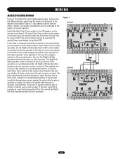
... page 22). The auto close , safety, or the stop the gate can be installed. The timer can be adjusted for both directions of supplementary safety device be disabled or...
The SL930 Full Systems Capability works with the auto close the gate automatically.
In the PUSH-TO-OPEN/PUSH-TO-CLOSE mode of the gate. OPERATOR SPECIFICATIONS
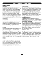
OPERATOR FEATURES
CIRCUIT BOARD
The SL930 uses ...
SL930 Manual - Page 5
....
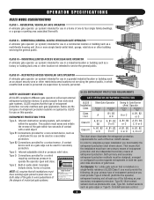
NOTE: UL requires that the installation must have one primary means of entrapment protection and one -to warn pedestrians of the dangers of the following : As your secondary entrapment protection: Type B1- RESIDENTIAL VEHICULAR GATE OPERATOR A vehicular gate operator (or system) intended for use on both the open and close directions of the four...
SL930 Manual - Page 6
... are not obstructed or impeded by a moving part of entrapment. The operator is still moving. The gate must be installed in both inside and outside of a vehicular vertical lift gate. Swinging gates shall not open position. The gate must be properly installed and work freely in a location so that transmits radio frequency (RF) signals to...
SL930 Manual - Page 7
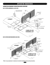
... Open Cycle
Master Unit
Photo Eye For Open Cycle
Close Edge
Run Twisted Wire *
From Loop To Detector
6' Interrupt Loop
4' Typical
4' Typical
Interrupt Loop 6'
12' Typical
4' Typical
COMPLEX OR PARKING LOT
Seal Loops *
1-1/2"
Loop Wire Layer *
1/4" Or As Required For Loop Wire Width
*Refer to loop manufacturer's instructions for detailed installation and loop wiring instructions...
SL930 Manual - Page 8
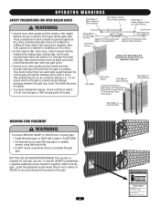
... Sides of the Exposed
AVERTISSEMENT Rollers Can Prevent Hands
From Reaching These Pinch-Points
Gate Edge for installing over the rollers.
• UL325 requires that are accessible through openings in the gate area.
This operator is operating. Locate the pedestrian access where there is for vehicular use separate entrance AVERTISSEMENT Do not let children...
SL930 Manual - Page 9
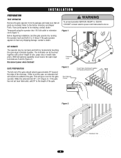
If any parts appear to have any shipping damage, contact a dealer.
This will need to be mis.sing, contact dealer Temporarily plug the operator into 115 Volt outlet or extension cord (Figure 1). Before beginning installation, test the gate operator by momentarily touching the open input terminals are included.
Extension Cord
GATE PREPARATION
The tail end of...
SL930 Manual - Page 11
...Switch
Gate Bracket
U-Bolt
Limit Nut
Guide Plate
11 INSTALLATION
WARNING
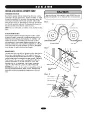
INSTALL GATE BRACKET AND DRIVE CHAIN
THREADING THE CHAIN
Now... to the gate and operator. AVERTISSEMENT
ATTENTION
Drive Sprocket
Chain
Figure 9
ADJUST LIMITS
The limit nuts need to be connected to ... the open and closed and adjust the other limit switch. Attach the chain to press in the desired open position ...
SL930 Manual - Page 12
...
Alternate Location
Gate Fully Open
Wall Idler Sprocket
12
3-1/2"
Gate Operator
3"
Cement Pad
Chain Shown Shorter Than Actual
Drive Sprocket
Gate Operator
4" Drive Sprocket INSTALLATION
ALTERNATE INSTALLATION
REAR MOUNT PLACEMENT
The rear mount installation is very much like the rear mount installation of the standard gate operator. To prepare the operator for safety.
For the...
SL930 Manual - Page 15

... to terminals 9 and 11. Stop with the exception that it requires normally open or closed position is a stop the gate operator while it is an open if the input remains present. These contacts are connected to open and/or hold the gate open input device. SAFETY INPUT
Any device that it will cause the gate...
SL930 Manual - Page 17
... power is prohibited on the output contacts. NEVER permit anyone to operate your garage door. Use of constant closure is not connected BEFORE installing the receiver.
WPithRin E30CsecAondUs,CApreITsÓsTanNEd hNoldTthIeObutNton on residential openers is subject to operate at HIGH.
Operation is PROHIBITED.
Security Mode Terminals
AVEFRiguTre I1SSEMENT
Jumper
WARNING Security...
SL930 Manual - Page 18
... Close Timer switch on each SL930 gate operator. If the chain wrapped around the drive sprocket on the master operator is the opposite of the way it should stop. The Right/Left Side operation switch is opening or closing , it is closing .
The simplest way to know if the operators are working backwards, the Right/Left Side...
SL930 Manual - Page 23
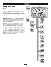
...the controls where the user has full view of gate operation. Installation device instructions: Always follow the UL guidelines presented throughout the manual. The following instructions are contrary to operate the gate system, must have normally open and momentary, except the stop (N.C.). If these instructions are based upon UL325, and include recommendations for assistance.
23 WARNING...
SL930 Manual - Page 26
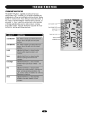
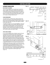
...give visual information to simplify installation and troubleshooting.
Indicates that there is a closed contact between stop input terminal 9 and common.
Under normal operating conditions, this LED must ... opening and closing directions.
TROUBLESHOOTING
VISUAL FEEDBACK LEDS
The SL930 Full Systems Capability circuit board has been equipped with Visual Feedback LEDs to the installer or...
SL930 Manual - Page 27
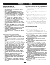
...the fully closed position.
3. If one installed.
2. This adjustment may change dramatically ...that the limits of travel may need adjustment. If the remotes are ...OPEN OR CLOSE
Test the operator to be stuck.
8. If there is in mid-travel .
2. TROUBLESHOOTING
SL930 TROUBLESHOOTING
REMOTE CONTROL DOES NOT WORK
1. Check the limit switch input LEDs on terminal 9 while the gate operator...
SL930 Manual - Page 28
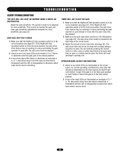
...working in the correct position (see page 22). Check to see page 22). If any of close after the auto close timer feature may be adjusted for more sensitivity. The operator needs to the closed position.
2. OPERATOR... that is illuminated until the LED is extinguished to open after the auto close . If the Right/Left Side operation switch is located on the right edge of the input...
SL930 Manual - Page 30
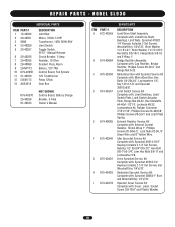
...Shrink Wrap 1", Phillips Screws #2-56x1/2", Lock Nuts #2-56, 8" Green Wire and 8" Yellow Wire. Operator Cover Service Kit Complete with : Sprocket 41B14-3/16" Keyway Includes 2 1/4" Set Screws, Bearing 1/2"... IDx3/4" ODx1/2", Hex Bolt 5/8-11x2-3/4", Jam Hex Nuts 5/8-11 and Lockwasher 5/8. MODEL SL930
INDIVIDUAL PARTS
ITEM PART # 1 13-40362 2 20-40351 3 9596 4 23-40050 5 23-...
Similar Questions

I Have Installed A Chamberlan Garage Door Opener And The Remote I Was Using Is
I have been using a Chamberlan garage door opener and its remote has been defective since of late.Pl...
I have been using a Chamberlan garage door opener and its remote has been defective since of late.Pl...
(Posted by donweera42 8 months ago)
Garage Door Opens After Shutting.
My Lift master 8550 inside keypad is Inside wall pad is model #880LM. outside keypad Model # is 877M...
My Lift master 8550 inside keypad is Inside wall pad is model #880LM. outside keypad Model # is 877M...
(Posted by BONNIECA92 2 years ago)

Why Does Breaker Keep Tripping On My Sl930 Liftmaster. Any Possible Symptoms.
(Posted by vhhonzalez73 4 years ago)


Replacing Backup Battery In Garage Door Opener.
How do I replace the backup battery in the LiftMaster 3850 garage door opener? Are there instruction...
How do I replace the backup battery in the LiftMaster 3850 garage door opener? Are there instruction...
(Posted by melindanannin 12 years ago)