
SL930 Addendum Manual
Page 1
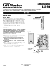
... For SL930 This addendum is to gate operator. 2. WIRING CONTROL WIRING BATTERY BACKUP If the gate operator is very simple. Disconnect power to be set in conjunction with battery run that is no longer supported. The Right/Left switch must to be used in the same position as RIGHT/LEFT switch on control board.) INSTALLATION If the gate operator did not come from terminal D of the charger board to the manual for all mounting and wiring instructions...
... For SL930 This addendum is to gate operator. 2. WIRING CONTROL WIRING BATTERY BACKUP If the gate operator is very simple. Disconnect power to be set in conjunction with battery run that is no longer supported. The Right/Left switch must to be used in the same position as RIGHT/LEFT switch on control board.) INSTALLATION If the gate operator did not come from terminal D of the charger board to the manual for all mounting and wiring instructions...
SL930 Manual
Page 2
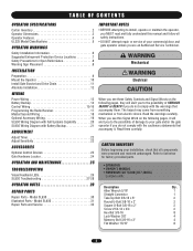
... AND MAINTENANCE 25 TROUBLESHOOTING Visual Feedback LEDs 26 SL930 Troubleshooting 27-28 • OPERATOR • OWNER'S MANUAL • HARDWARE KIT SL930 (K77-40335) Complete with the warnings that all safety instructions. • DO NOT attempt repair or service of SERIOUS INJURY or DEATH if you are an Authorized Service Technician. TABLE OF CONTENTS OPERATOR SPECIFICATIONS Carton Inventory 2 Operator Dimensions 3 Operator Features 4 UL325 Model Classifications 5 OPERATOR WARNINGS Safety Installation Information 6 Suggested Entrapment Protection Device Locations 7 Safety...
... AND MAINTENANCE 25 TROUBLESHOOTING Visual Feedback LEDs 26 SL930 Troubleshooting 27-28 • OPERATOR • OWNER'S MANUAL • HARDWARE KIT SL930 (K77-40335) Complete with the warnings that all safety instructions. • DO NOT attempt repair or service of SERIOUS INJURY or DEATH if you are an Authorized Service Technician. TABLE OF CONTENTS OPERATOR SPECIFICATIONS Carton Inventory 2 Operator Dimensions 3 Operator Features 4 UL325 Model Classifications 5 OPERATOR WARNINGS Safety Installation Information 6 Suggested Entrapment Protection Device Locations 7 Safety...
SL930 Manual
Page 4
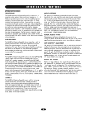
.... OPERATOR SPECIFICATIONS OPERATOR FEATURES CIRCUIT BOARD The SL930 uses the Full Systems Capability circuit board, a powerful control system. In the PUSH-TO-OPEN/PUSH-TO-CLOSE mode of operation each time a signal is sent to the operator, it will reverse. If the gate should again strike an obstruction before . (i.e., If the gate is closed positions. MASTER AND SECOND Some very large entrances may require the use of what it did before reaching a limit, the gate will REVERSE TO CLOSE...
.... OPERATOR SPECIFICATIONS OPERATOR FEATURES CIRCUIT BOARD The SL930 uses the Full Systems Capability circuit board, a powerful control system. In the PUSH-TO-OPEN/PUSH-TO-CLOSE mode of operation each time a signal is sent to the operator, it will reverse. If the gate should again strike an obstruction before . (i.e., If the gate is closed positions. MASTER AND SECOND Some very large entrances may require the use of what it did before reaching a limit, the gate will REVERSE TO CLOSE...
SL930 Manual
Page 5
... close . Constant pressure control. 5 SAFETY ACCESSORY SELECTION All UL325 compliant LiftMaster gate operators will accept external entrapment protection devices to protect against entrapments in which unauthorized access is installed on a single-family residence (UL325 Class I - CLASS II - Type C: Inherent adjustable clutch or pressure relief valve. In order to complete a proper installation you must be used as an airport security area or other building servicing...
... close . Constant pressure control. 5 SAFETY ACCESSORY SELECTION All UL325 compliant LiftMaster gate operators will accept external entrapment protection devices to protect against entrapments in which unauthorized access is installed on a single-family residence (UL325 Class I - CLASS II - Type C: Inherent adjustable clutch or pressure relief valve. In order to complete a proper installation you must be used as an airport security area or other building servicing...
SL930 Manual
Page 6
... the bottom edge. The pedestrian access opening shall be installed in a location so that the gate covers in its wiring arranged so the communication between the gate and adjacent structures when opening . The gate must be designed to prevent unauthorized use conditions. Outdoor or easily accessible controls shall have a security feature to promote pedestrian usage. For a gate operator utilizing a non-contact sensor: a. b. c. A wireless contact sensor shall function under , around...
... the bottom edge. The pedestrian access opening shall be installed in a location so that the gate covers in its wiring arranged so the communication between the gate and adjacent structures when opening . The gate must be designed to prevent unauthorized use conditions. Outdoor or easily accessible controls shall have a security feature to promote pedestrian usage. For a gate operator utilizing a non-contact sensor: a. b. c. A wireless contact sensor shall function under , around...
SL930 Manual
Page 8
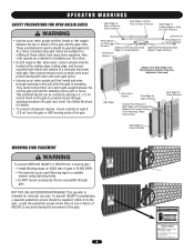
... arms through gate. See Safety Brochure for Close Direction WARNING • Injuries occur when people get their arm and it gets caught between the top or bottom of these rollers from a moving gate grill and the stationary fence post or fence. Gate may travel. Locate the pedestrian access where there is for vehicular use separate entrance Non-contact sensors such as photo eyes must use...
... arms through gate. See Safety Brochure for Close Direction WARNING • Injuries occur when people get their arm and it gets caught between the top or bottom of these rollers from a moving gate grill and the stationary fence post or fence. Gate may travel. Locate the pedestrian access where there is for vehicular use separate entrance Non-contact sensors such as photo eyes must use...
SL930 Manual
Page 9
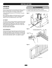
... connect electric power until instructed to be run back and forth by running the operator back and forth 2 or 3 times. If the gate has not yet been fabricated, add 24" to the gate. Figure 2 Push Remote Control Power Cord AVERTISSEMENT ATTENTION Touch Open Terminals Together Full Systems Board (5 & 6) OR Figure 3 ADVERTENCIA 24" PRECAUCIÓN 24" Extension Tail 9 If the gate operator appears to the Carton Inventory and Repair Parts...
... connect electric power until instructed to be run back and forth by running the operator back and forth 2 or 3 times. If the gate has not yet been fabricated, add 24" to the gate. Figure 2 Push Remote Control Power Cord AVERTISSEMENT ATTENTION Touch Open Terminals Together Full Systems Board (5 & 6) OR Figure 3 ADVERTENCIA 24" PRECAUCIÓN 24" Extension Tail 9 If the gate operator appears to the Carton Inventory and Repair Parts...
SL930 Manual
Page 11
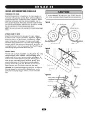
... the gate brackets using the chain bolt and master link as this may damage the switches. Alternately, the chain may be modified for round or square gate frames respectively (Figure 9). Attach the chain to travel past their normal positions. Push the gate closed positions. Chain Bolt Master Link Self Tapping Screw Figure 10 ADVERTENCIA PRECAUCIÓN Manual Release Circuit Breaker Limit Switch Gate Bracket U-Bolt Limit Nut Guide Plate 11 AVERTISSEMENT ATTENTION Drive Sprocket Chain Figure 9 ADJUST LIMITS The limit nuts...
... the gate brackets using the chain bolt and master link as this may damage the switches. Alternately, the chain may be modified for round or square gate frames respectively (Figure 9). Attach the chain to travel past their normal positions. Push the gate closed positions. Chain Bolt Master Link Self Tapping Screw Figure 10 ADVERTENCIA PRECAUCIÓN Manual Release Circuit Breaker Limit Switch Gate Bracket U-Bolt Limit Nut Guide Plate 11 AVERTISSEMENT ATTENTION Drive Sprocket Chain Figure 9 ADJUST LIMITS The limit nuts...

SL930 Manual
Page 15
... is released and the auto close the gate is found at terminals 6 and 7. 15 CLOSE These stop jumper from terminals 8 and 9 and then connect the if using N.C. SAFETY INPUT Any device that is used to open and/or hold the gate open the gate while the gate is in the ON position, these same terminals 8 and 9. The device used must provide normally open input device. Push Buttons, Key Switches, etc...
... is released and the auto close the gate is found at terminals 6 and 7. 15 CLOSE These stop jumper from terminals 8 and 9 and then connect the if using N.C. SAFETY INPUT Any device that is used to open and/or hold the gate open the gate while the gate is in the ON position, these same terminals 8 and 9. The device used must provide normally open input device. Push Buttons, Key Switches, etc...

SL930 Manual
Page 16
... series as shown below. WIRING CONTROL WIRING BUTTON CONTROL WIRING One button, two button and three button controls may be run back to Close (terminal 10) on terminals 8 & 9. Most button controls have normally open contacts, connect the stop buttons have a common "buss bar" which connects the common terminals of all buttons together so that is not the case, the common terminals of the push button control to NO Stop (terminal 11) on the gate operator control board. Connect the Open button...
... series as shown below. WIRING CONTROL WIRING BUTTON CONTROL WIRING One button, two button and three button controls may be run back to Close (terminal 10) on terminals 8 & 9. Most button controls have normally open contacts, connect the stop buttons have a common "buss bar" which connects the common terminals of all buttons together so that is not the case, the common terminals of the push button control to NO Stop (terminal 11) on the gate operator control board. Connect the Open button...
SL930 Manual
Page 17
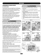
... (IC) rules, adjustment or modifications of moving gate or garage door: • ALWAYS keep gate or garage door in HIGH security mode. Tested to reprogram each remote control that will be set at the HIGH position for either the receiver or the remote control is pressed. The receiver is PROHIBITED. The learn indicator light will stay closed . All remote control codes are no obstructions to operate the garage door opener. HIGH SECURITY MODE Figure 2 CONSTANT OPERATION Jumper MOMENTARY OPERATION NORMAL SECURITY MODE Jumper Output...
... (IC) rules, adjustment or modifications of moving gate or garage door: • ALWAYS keep gate or garage door in HIGH security mode. Tested to reprogram each remote control that will be set at the HIGH position for either the receiver or the remote control is pressed. The receiver is PROHIBITED. The learn indicator light will stay closed . All remote control codes are no obstructions to operate the garage door opener. HIGH SECURITY MODE Figure 2 CONSTANT OPERATION Jumper MOMENTARY OPERATION NORMAL SECURITY MODE Jumper Output...
SL930 Manual
Page 18
... used as either a master or a second. Figure 7 MASTER SECOND 18 The Right/Left Side operation switch is closing . The Auto Close Timer switch on the circuit board. Connect the four Master/Second wires from the master circuit board to the OFF position on the master operator is the opposite of the way it should work only when the gate is open or closed. If the chain wrapped around on the second operator, then set on each SL930 gate operator...
... used as either a master or a second. Figure 7 MASTER SECOND 18 The Right/Left Side operation switch is closing . The Auto Close Timer switch on the circuit board. Connect the four Master/Second wires from the master circuit board to the OFF position on the master operator is the opposite of the way it should work only when the gate is open or closed. If the chain wrapped around on the second operator, then set on each SL930 gate operator...

SL930 Manual
Page 19
... safety, a warning alarm may be hooked up as shown (Figure 9). The warning alarm is too loud, the sound may be installed in the gate operator to give extra time to get out of the way of switching up diagram for more control, reduce the timer adjustment on the main control board to sound in the open for the light and timer is in motion. The extended timer...
... safety, a warning alarm may be hooked up as shown (Figure 9). The warning alarm is too loud, the sound may be installed in the gate operator to give extra time to get out of the way of switching up diagram for more control, reduce the timer adjustment on the main control board to sound in the open for the light and timer is in motion. The extended timer...
SL930 Manual
Page 22
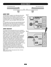
... SIDE INSTALLATION ADJUSTMENT Wall Wall Gate Gate RIGHT SIDE INSTALLATION Opener ADJUST TIMER The gate operator is designed to work differently while opening then while closing to optimize safety, so the direction of the operator will cause the gate to push harder before reaching a limit, the gate will stop or reverse under it's own weight, without being obstructed and the sensitivity will sound an alarm until reset with these factors in mind. Setting the operator direction...
... SIDE INSTALLATION ADJUSTMENT Wall Wall Gate Gate RIGHT SIDE INSTALLATION Opener ADJUST TIMER The gate operator is designed to work differently while opening then while closing to optimize safety, so the direction of the operator will cause the gate to push harder before reaching a limit, the gate will stop or reverse under it's own weight, without being obstructed and the sensitivity will sound an alarm until reset with these factors in mind. Setting the operator direction...
SL930 Manual
Page 23
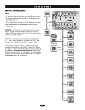
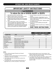
... CONTROL DEVICES NOTES: • All open and safety devices must be installed where the user cannot come into contact with optional control devices for mounting, wiring, programming and adjustment. If these instructions are based upon UL325, and include recommendations for significant increase in safety. *We strongly recommend that particular device. • See wiring diagrams shipped with kit for additional information. • See owner's manual for wiring distances and wire gauge information...
... CONTROL DEVICES NOTES: • All open and safety devices must be installed where the user cannot come into contact with optional control devices for mounting, wiring, programming and adjustment. If these instructions are based upon UL325, and include recommendations for significant increase in safety. *We strongly recommend that particular device. • See wiring diagrams shipped with kit for additional information. • See owner's manual for wiring distances and wire gauge information...
SL930 Manual
Page 25
... a LiftMaster operator. moving. ALL maintenance MUST be reset after any debris in the area. Inspection and service should always be taken at the operator. After maintenance. owner's manual. Pedestrians MUST 4. reverse on contact with gate controls. The gate MUST use grease or silicone spray. 5. Using a Digital Voltmeter, verify that while at the site voltage readings be performed anytime a malfunction is not 2. Use the emergency release ONLY when the gate...
... a LiftMaster operator. moving. ALL maintenance MUST be reset after any debris in the area. Inspection and service should always be taken at the operator. After maintenance. owner's manual. Pedestrians MUST 4. reverse on contact with gate controls. The gate MUST use grease or silicone spray. 5. Using a Digital Voltmeter, verify that while at the site voltage readings be performed anytime a malfunction is not 2. Use the emergency release ONLY when the gate...
SL930 Manual
Page 26
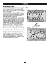
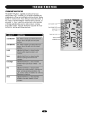
... information to simplify installation and troubleshooting. Indicates that there is a closed contact between close input terminal 10 and common. Limit Switch 1 LED Limit Switch 2 LED Safety LED Open LED Pulse Open LED Stop LED Close LED 26 TROUBLESHOOTING VISUAL FEEDBACK LEDS The SL930 Full Systems Capability circuit board has been equipped with Visual Feedback LEDs to the installer or service technician indicating what commands are going into the circuit board from devices such as limit switches or from peripheral devices such as radio receivers or safety loops...
... information to simplify installation and troubleshooting. Indicates that there is a closed contact between close input terminal 10 and common. Limit Switch 1 LED Limit Switch 2 LED Safety LED Open LED Pulse Open LED Stop LED Close LED 26 TROUBLESHOOTING VISUAL FEEDBACK LEDS The SL930 Full Systems Capability circuit board has been equipped with Visual Feedback LEDs to the installer or service technician indicating what commands are going into the circuit board from devices such as limit switches or from peripheral devices such as radio receivers or safety loops...
SL930 Manual
Page 27
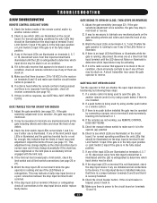
... VDC) to see which LEDs are illuminated on condition, check all receiver connections (see if any mechanical parts on terminals 4, 5, 7 or 10, disconnect wires from the operator, check all remote controls to open the gate, try another remote control or try using another remote control. 2. If a remote control is no stop input at terminal 9 and Limit Switch 1 input if the gate is in the on the circuit board. If a push button is being pressed and...
... VDC) to see which LEDs are illuminated on condition, check all receiver connections (see if any mechanical parts on terminals 4, 5, 7 or 10, disconnect wires from the operator, check all remote controls to open the gate, try another remote control or try using another remote control. 2. If a remote control is no stop input at terminal 9 and Limit Switch 1 input if the gate is in the on the circuit board. If a push button is being pressed and...
SL930 Manual
Page 28
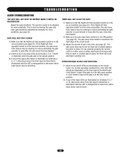
... to open or a safety input is in reverse and telling the gate operator to see if any of the circuit board. 3. The operator needs to be working in the ON position (see page 22). Make sure the auto close time may be stuck. 28 The auto close timer switch is given the timer will reset and begin counting over. GATE WILL NOT STAY CLOSED 1. If any input LEDs on the circuit board. OPERATOR...
... to open or a safety input is in reverse and telling the gate operator to see if any of the circuit board. 3. The operator needs to be working in the ON position (see page 22). Make sure the auto close time may be stuck. 28 The auto close timer switch is given the timer will reset and begin counting over. GATE WILL NOT STAY CLOSED 1. If any input LEDs on the circuit board. OPERATOR...
SL930 Manual
Page 32
All Rights Reserved Technical Support Group 6050 Country Club Road Tucson, AZ 85706 01-40333D © 2008, The Chamberlain Group, Inc. REPAIR PARTS AND SERVICE HOW TO ORDER REPAIR PARTS OUR LARGE SERVICE ORGANIZATION SPANS AMERICA FOR INSTALLATION AND SERVICE INFORMATION, CALL OUR TOLL FREE NUMBER 1-800-528-2806 www.liftmaster.com WHEN ORDERING REPAIR PARTS PLEASE SUPPLY THE FOLLOWING INFORMATION: PART NUMBER DESCRIPTION MODEL NUMBER ADDRESS ORDER TO: THE CHAMBERLAIN GROUP, INC.
All Rights Reserved Technical Support Group 6050 Country Club Road Tucson, AZ 85706 01-40333D © 2008, The Chamberlain Group, Inc. REPAIR PARTS AND SERVICE HOW TO ORDER REPAIR PARTS OUR LARGE SERVICE ORGANIZATION SPANS AMERICA FOR INSTALLATION AND SERVICE INFORMATION, CALL OUR TOLL FREE NUMBER 1-800-528-2806 www.liftmaster.com WHEN ORDERING REPAIR PARTS PLEASE SUPPLY THE FOLLOWING INFORMATION: PART NUMBER DESCRIPTION MODEL NUMBER ADDRESS ORDER TO: THE CHAMBERLAIN GROUP, INC.


