
Dell PowerEdge 2950 Support Question
Dell PowerEdge 2950 Support Question
Find answers below for this question about Dell PowerEdge 2950.Need a Dell PowerEdge 2950 manual? We have 8 online manuals for this item!
Question posted by shanearlierep on January 17th, 2014
How To Install Poweredge 2950 Cable Management Arms With System Status
indicator
Current Answers
Related Dell PowerEdge 2950 Manual Pages
Installing a SATA Optical Drive - Page 4

...with the SATA drive installation kit.
If you must be replaced with the drive tray provided with the system is used for the SATA optical drive. Replacing a PowerEdge 2950 or 2970 Optical Drive
...fit into place. The pins on the left side of the drive.
4
Installing a SATA Optical Drive On PowerEdge 1950 systems, the existing optical drive tray must remove the old drive and interposer...
Installing a SATA Optical Drive - Page 5

... to attach the drive to the old drive.
See Figure 1-2. Installing a SATA Optical Drive
5 Replacing the Optical Drive in a PowerEdge 2950 or 2970 System
2 1
3
4
5
6
7
1 optical drive 3 interposer 5 SATA power cable 7 optical drive carrier
2 interposer release latch 4 SATA cable 6 carrier latch
Replacing a PowerEdge 1950 Optical Drive
NOTE: The replacement drive tray provided in the...
Installing a SATA Optical Drive - Page 8

... Owner's Manual.
5 Remove the cable retention bracket from the right interior wall of the chassis by pushing the blue release latch and sliding the bracket toward the front of the system until the bracket detaches from the chassis slots.
6 Route the SATA cable in the cable channel in the PowerEdge 2950 and 2970
1
2
3 4 5
1 SATA_B connector...
Information Update - Page 3
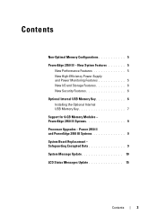
... 9 System Message Update 10 LCD Status Messages Update 15
Contents
3 Contents
Non-Optimal Memory Configurations 5 PowerEdge 2950 III - New System Features 5
New Performance Features 5 New High-Efficiency Power Supply and Power Monitoring Features 5 New I/O and Storage Features 6 New Security Features 6 Optional Internal USB Memory Key 6 Installing the Optional Internal USB Memory Key...
Information Update - Page 5

... Power Supply and Power Monitoring Features
• Higher system efficiency on power conversion across workloads. • Baseboard Management Control (BMC) power monitoring monitors
current, voltage, and power utilization in the DIMM set for Setup
NOTE: Mixing....
The system clocks down the performance to continue or F2 for the channel. Information Update
5
PowerEdge 2950 III -
Information Update - Page 9
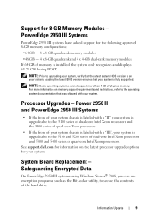
...system is upgradeable to secure the contents of memory is labeled with your system. Safeguarding Encrypted Data
On PowerEdge 2950 III systems using Windows Server® 2008, you can use encryption programs, such as the BitLocker utility, to the 5100 series... processors.
For more than 4 GB of your system chassis is installed, the system only recognizes and displays 63.75 GB during POST.
Information Update - Page 10
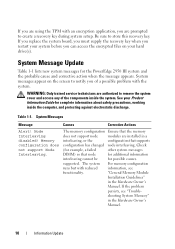
... information
interleaving cannot be
for the PowerEdge 2950 III system and the probable cause and corrective action when the message appears. "General Memory Module
Installation Guidelines"
in the Hardware Owner's
...you replace the system board, you must supply the recovery key when you are installed in a
interleaving, or the
configuration that the memory
does not support node
modules...
Information Update - Page 15
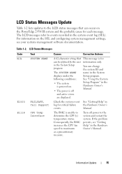
... as a precautionary measure.
For information on the PowerEdge 2950 III system and the probable cause for critical failure events.
See "Getting Help" in the Hardware Owner's Manual. If the problem persists, see your systems management software documentation.
This message is unable to determine the CPU(s) temperature status.
Table 1-2.
See "Using the System Setup Program...
Information Update - Page 24
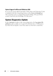
... Build and Update Utility, Microsoft® Windows® 2000 is supported by the PowerEdge 2950 and 2950 II systems, but not by the PowerEdge 2950 III system. System Support for Microsoft Windows 2000
If you to a hard drive.
24
Information Update System Diagnostics Update
In the Customize window of operating systems on the Server OS Install tab.
Information Update - Page 46
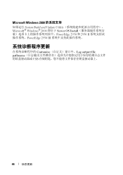
Microsoft Windows 2000
System Build and Update Utility Microsoft® Windows® 2000 将位于 Server OS Install PowerEdge 2950 和 2950 II PowerEdge 2950 III
Customize Log output file pathname USB
46
信息更新
Information Update - Page 132
...; cat/sys/devices/system/cpu/cpuxx/cpufreq/scaling_ cur_freq
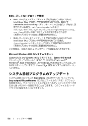
• RHEL 3 9 Intel Xeon 54xx proc/cpuinfo
RHEL 4
Microsoft Windows 2000
System Build and Update Utility Server OS Install OS OS Microsoft® Windows® 2000 PowerEdge 2950/2950 II OS PowerEdge 2950 III
Customize Log output file pathname USB
132
Hardware Owner's Manual (PDF) - Page 63
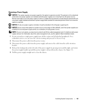
... AC power source. The system is powered on the left power supply bay (1). NOTICE: If you may have to unlatch and lift the cable management arm if it must be installed in the left side of the power supply by pressing in toward the right, and rotate the power-supply handle up until the...
Rack Installation Guide - Page 5
...Rack 9 Configuring the Sliding Rail Assemblies 11 Installing the Mounting Rails in the Rack 12
Installing RapidRails Mounting Rails 12 Installing the VersaRails Mounting Rails 13 Installing the System in the Rack 15 Removing the System From the Rack 16 Installing the Cable-Management Arm 17 Routing Cables 18 Attaching the Cable-Management Arm Ramp Assembly 19 Replacing the Rack Doors 21...
Rack Installation Guide - Page 9

..., always install the stabilizer(s) before installing systems in a rack could cause the rack to the back of threads per inch is identified as a 10-32 screw.
See the documentation provided with 32 threads per inch. NOTE: Both the right and left cable-management arm ramp assembly • One right cable-management arm ramp assembly • One status indicator cable (if applicable...
Rack Installation Guide - Page 10
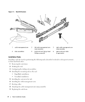
Rack Kit Contents 1
3 2
4
6
5
1 cable-management arm 4 slide assemblies
2 left cable-management arm ramp assembly
5 10-32 x 0.5-inch flange-head Phillips screws (8)
3 right cable-management arm ramp assembly
6 status indicator cable (if applicable)
Installation Tasks
Installing a rack kit involves performing the following tasks (described in detail in subsequent sections) in their numbered ...
Rack Installation Guide - Page 17
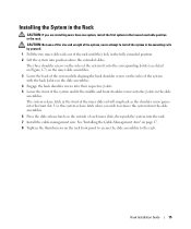
The system release latch at the front of each inner slide, then push the system into the rack. 7 Install the cable-management arm. Rack Installation Guide
15 Use this system release latch when you are installing more than one system, install the first system in the lowest available position in the slide
assemblies. The three shoulder screws on...
Rack Installation Guide - Page 19

... the system forward.
6 Pull the system completely out of the rack. Installing the Cable-Management Arm
1
2
3
back of the rack cabinet.
CAUTION: Both ends of the cable-management arm must be connected before you attach the cablemanagement arm.
1 Fit the latch on the front end of the cable-management arm onto the bracket on the end of the mounting rail until...
Rack Installation Guide - Page 20

... status-indicator cable connector 4 wire cable basket
2 If applicable, connect the system status-indicator cable to provide strain relief for the power cables.
4 Route the cables along the bend in the cable-management arm.
5 Adjust the cable slack as needed at the hinge position and secure the cables with the tie wraps (see Figure 1-9).
6 Close the cable basket.
18
Rack Installation Guide...
Rack Installation Guide - Page 21

...the metal ramp facing toward the center of the rack (see Figure 1-10). Figure 1-10. Attaching the Cable-Management Arm Ramp Assembly
The cable-management arm ramp assembly guides the cable-management arm into the rack. CAUTION: The cable-management arm ramp assembly must be installed to its furthest extension, the slide assemblies will lock in the extended position. Orientation for the Left...
Rack Installation Guide - Page 22

... each time the system is attached to the right side of the rack.
20
Rack Installation Guide Figure 1-11. 1
Installing the Cable-Management Arm Ramp Assembly
3 2
4
5
6
1 ramp assembly bracket 4 ramp assembly seating catch
2 cable-management arm ramp assembly latch
5 left cable-management arm ramp assembly
3 ramp assembly release button
6 ramp assembly wireform guide
NOTE: In Figure 1-11...
Similar Questions


How To Install Os On One Of The Blades Server In A Poweredge M1000e Enclosure
(Posted by doccan 9 years ago)


How To Install Dell Poweredge 2950 Cable Management Arm Install Instruction
(Posted by cmsa 10 years ago)
