
Dell PowerEdge 1900 Support Question
Dell PowerEdge 1900 Support Question
Find answers below for this question about Dell PowerEdge 1900.Need a Dell PowerEdge 1900 manual? We have 7 online manuals for this item!
Question posted by tklady on September 6th, 2014
Poweredge 1900 5/e How To Replace Battery
The person who posted this question about this Dell product did not include a detailed explanation. Please use the "Request More Information" button to the right if more details would help you to answer this question.
Current Answers
Related Dell PowerEdge 1900 Manual Pages
Hardware Owner's Manual (PDF) - Page 5

... Modules 83 Removing Memory Modules 85
Installing a RAC Card 85
Activating the Integrated NIC TOE 87
Microprocessor 87 Replacing a Processor 88
SAS RAID Controller Daughter Card 92 Replacing the SAS RAID Controller Daughter Card Battery 92 Removing the SAS RAID Controller Daughter Card 93 Installing the SAS RAID Controller Daughter Card 95
Configuring...
Hardware Owner's Manual (PDF) - Page 17
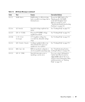
... acceptable operating range. If the problem persists, see "Getting Help" on page 131. See
bad, or unable to recharge due to "Replacing the SAS RAID
thermal issues. Controller Daughter Card
Battery" on page 92, and
"Troubleshooting System Cooling
Problems" on support.dell.com for the most current system information.
About Your System...
Hardware Owner's Manual (PDF) - Page 22
... Fully Buffered DIMM (FBD) memory subsystem link on page 110. For example, if the code E0780 MISSING CPU 1 appears, you know that the RAID Replace RAID battery. messages can often specify a very precise fault condition that the problem is easily corrected.
The code on the LCD can display sequentially
on page 155...
Hardware Owner's Manual (PDF) - Page 29
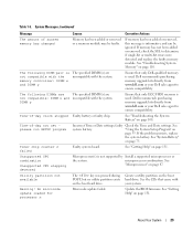
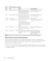
...(s) is used .
See "Getting Help" on page 131.
If the problem persists, replace
the system battery. See "Getting Help" on page 131.
microprocessor combination. Utility partition not available
The key...Dell sales agent to determine if single-bit or multi-bit errors were detected and replace the faulty memory module.
"Using the System Setup Program" on the boot hard ...
Hardware Owner's Manual (PDF) - Page 66
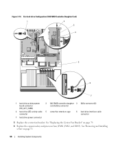
... Daughter Card)
1
2
3
4
5
6
7
1 hard drive activity system board connector (HD_ACT_CARD)
2 SAS RAID controller daughter 3 SASx connector (2) card battery connector
4 hard drive LED activity cable 5 center fan retention cage connector
6 hard drive interface cable connector
7 hard drive power connector
5 Replace the center fan bracket. See "Removing and Installing a Fan" on page 79...
Hardware Owner's Manual (PDF) - Page 75
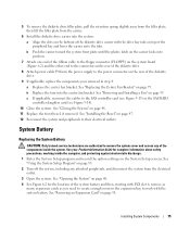
... into the center fan bracket. System Battery
Replacing the System Battery
CAUTION: Only trained service technicians are authorized to remove the system cover and access ...with the drive bay tabs on top of the system battery and then, starting with PCI slot 6, remove as
many expansion cards as you need to create enough room in step 4: a Replace the center fan bracket. See "Installing the Bezel"...
Hardware Owner's Manual (PDF) - Page 76
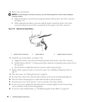
... the securing tabs at the negative side of connector
6 Install the new system battery (see "Troubleshooting the System Battery" on page 57.
8 Close the system. Replacing the System Battery
1
2
3
1 positive side of connector
2 system battery
3 negative side of the connector. 5 Remove the system battery. NOTICE: To avoid damage to enter the correct time and date. 12...
Hardware Owner's Manual (PDF) - Page 92
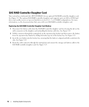
...INT STORAGE) for an optional SAS RAID controller daughter card. Replacing the SAS RAID Controller Daughter Card Battery
1 Disconnect the battery cable from the expansion-bay bracket by releasing the tab ... Route the cable connector through the routing hole on the daughter card and pulling the battery cable free.
See Figure 3-8. The optional SAS RAID controller daughter card supports up your ...
Hardware Owner's Manual (PDF) - Page 93
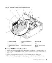
... by releasing the tab on the cable connector on the system board. See Figure 3-26. Replacing a SAS RAID Controller Daughter Card Battery
8
9
1
7
2 6
5
4 3
1 connector release tab
2 routing hole for RAID battery 3 RAID battery cable cable
4 expansion-bay bracket
5 battery bay
6 RAID battery
7 SAS RAID controller daughter 8 hard drive LED activity cable 9 hard drive LED activity...
Hardware Owner's Manual (PDF) - Page 94
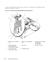
... Card
8
7
1
6 2
5
4 3
1 SAS RAID controller daughter 2 card
4 hard drive LED activity
5
indicator system board
connector (HD_ACT_CARD)
7 hard drive LED activity
8
indicator cable connector
RAID battery cable (SAS RAID 3 only)
slide rails (2)
6
SAS RAID connector 1
SAS RAID controller daughter card slot socket (INT_STORAGE)
SAS RAID connector 0
94
Installing System Components...
Hardware Owner's Manual (PDF) - Page 117
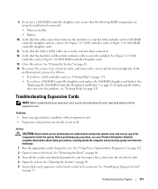
... 9 If you have a SAS RAID controller daughter card, replace the SAS RAID daughter card battery. Problem • Error message indicates a problem with an ...Server Administrator Diagnostics" on page 46. 3 Turn off the system and attached peripherals, and disconnect the system from the electrical outlet. 4 Open the system. See "Opening the System" on page 131. If replacing the battery...
Hardware Owner's Manual (PDF) - Page 165
... backup unit, 68
POST accessing system features, 10
power supply installing, 51 removing, 50 troubleshooting, 108
processor replacing, 88
R
RAC card installing, 85
RAID controller. See SAS controller daughter card
SAS RAID controller daughter card
battery replacement, 92 troubleshooting, 116
securing your system, 42
serial I/O device troubleshooting, 105
setup password assigning, 43 changing...
Information Update - Page 1
Dell™ PowerEdge™ 1900 Systems
Information Update
www.dell.com | support.dell.com
Installing a SATA Optical Drive - Page 3

...the System" in which an existing PATA or IDE optical drive is being replaced by a SATA optical drive.
Before you begin this procedure, review the ...the SAS cable from the SAS controller and pull the cable away from the back of the optical drive.
6 PowerEdge 2900 and 1900 systems only: Perform the following steps. See "Removing a SAS Controller Daughter Card" in your Hardware Owner's Manual...
Installing a SATA Optical Drive - Page 4
... that shipped with the SATA drive installation kit. The PowerEdge 2900 and 1900 systems do not reuse the interposer board attached to the old drive.
1 Pull outward on the carrier fit into place. Replacing a PowerEdge 2950 or 2970 Optical Drive
NOTE: If you must be replaced with the drive tray provided with the system is...
Installing a SATA Optical Drive - Page 5

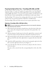
... or 2970 System
2 1
3
4
5
6
7
1 optical drive 3 interposer 5 SATA power cable 7 optical drive carrier
2 interposer release latch 4 SATA cable 6 carrier latch
Replacing a PowerEdge 1950 Optical Drive
NOTE: The replacement drive tray provided in the installation kit must be used with the holes in the side of the SATA optical drive into the tray until ...
Installing a SATA Optical Drive - Page 6

...kit.
4 Route the SATA cable to the power supply connector. NOTE: You may need to replace the existing power cable with the branching power cable) to the back of the chipset shroud.... Figure 1-2. a Route the cable through the power cable cutout in a PowerEdge 1950 Drive Tray 2 3
1 4
5
1 optical drive 3 SATA power cable 5 optical drive carrier
2 SATA ...
Installing a SATA Optical Drive - Page 8

...optical drive
8
Installing a SATA Optical Drive See Figure 1-4.
7 Route the SATA cable along the top of the chassis and replace the cable retention bracket over the cable.
See "Removing the Cooling Shroud" in your Hardware Owner's Manual.
5 Remove the cable...slots.
6 Route the SATA cable in the cable channel in the PowerEdge 2950 and 2970
1
2
3 4 5
1 SATA_B connector on the system board.
Installing a SATA Optical Drive - Page 9

... bracket.
See "Installing the Cooling Shroud" in your Hardware Owner's Manual.
10 Close the system. For a PowerEdge 1900 system, connect to the CD/TBU connector on the system board. See Figure 1-5.
- Installing the SATA Optical Drive - 9 Replace the cooling shroud. See "Closing the System" in your Hardware Owner's Manual.
11 Reconnect the system...
Installing a SATA Optical Drive - Page 10

... Reconnect the system to the SAS controller daughter card.
9 Close the system. Figure 1-5. See "Closing the System" in a PowerEdge 2900 or 1900
3
2
4
5 1
1 optical drive 3 SATA data cable 5 SATA power connector on SAS
backplane (PowerEdge 2900 only)
2 SATA power cable 4 SATA connector on system board
8 Reconnect the cables to power and turn on the...
Similar Questions


How To Replace Battery On Perc 5 I Poweredge 1900
(Posted by nanazsun 10 years ago)


How To Replace Battery Dell Poweredge 2950 W1228 Romb Batt
(Posted by kencjes 10 years ago)