User Guide
Page 1
... cord. Only connect this computer to a power outlet that matches the power requirements of all products plugged into it from overheating, do not block or cover these instructions for cleaning. 10 Do not use this computer, make sure that the total amperage rating of all of any kind into a grounding-type...
... cord. Only connect this computer to a power outlet that matches the power requirements of all products plugged into it from overheating, do not block or cover these instructions for cleaning. 10 Do not use this computer, make sure that the total amperage rating of all of any kind into a grounding-type...
User Guide
Page 2
...adjustment of the following precautions: 1 The power supply cord must be unplugged before the main system unit cover is removed. (Separe le cordon d'alimentation et puis enleve le couvercle.) 2 Once removed, the cover must be replaced and screwed in position before the power supply cord is damaged or frayed. 2 ... operation. Unplug this product from the main power outlet and call for service. Stop If you ever have to remove the main system unit cover, observe the following conditions: 1 If the power cord or plug is plugged back in performance indicating a need for service under any of ...
...adjustment of the following precautions: 1 The power supply cord must be unplugged before the main system unit cover is removed. (Separe le cordon d'alimentation et puis enleve le couvercle.) 2 Once removed, the cover must be replaced and screwed in position before the power supply cord is damaged or frayed. 2 ... operation. Unplug this product from the main power outlet and call for service. Stop If you ever have to remove the main system unit cover, observe the following conditions: 1 If the power cord or plug is plugged back in performance indicating a need for service under any of ...
User Guide
Page 8
Chapter 4 Installing and Removing Drives Removing the Cover 4-1 Replacing the Cover 4-3 Installing an Expansion Card 4-4 Installing an Additional Hard Disk Drive 4-6 Installing the 5.25-inch Device in the Peripheral Bay 4-9 Chapter 5 Using the Restore CDs Restoring ...
Chapter 4 Installing and Removing Drives Removing the Cover 4-1 Replacing the Cover 4-3 Installing an Expansion Card 4-4 Installing an Additional Hard Disk Drive 4-6 Installing the 5.25-inch Device in the Peripheral Bay 4-9 Chapter 5 Using the Restore CDs Restoring ...
User Guide
Page 23
... power source and from any telecommunications links, networks, or modems before performing any cables connected to install or remove system cover, optional drives, and optional cards in this chapter. To remove the cover, follow these steps: 1. Turn off the computer. Chapter 1 2. Installing and Removing Drives 4-1 NOTE Turn off the ...your computer. Then disconnect the computer from the back panel. Then disconnect any of the procedures described in your system to remove the cover of all, disconnect the power cable from the electrical outlet and from its internal components.
... power source and from any telecommunications links, networks, or modems before performing any cables connected to install or remove system cover, optional drives, and optional cards in this chapter. To remove the cover, follow these steps: 1. Turn off the computer. Chapter 1 2. Installing and Removing Drives 4-1 NOTE Turn off the ...your computer. Then disconnect the computer from the back panel. Then disconnect any of the procedures described in your system to remove the cover of all, disconnect the power cable from the electrical outlet and from its internal components.

User Guide
Page 24
To open the system cover, remove two screws on the back panel of your system every time you touch a component. 4-2 Installing and Removing Drives Set the cover aside. NOTE Be sure to free it from the system and lift it off until can be removed completely. Slide the cover toward the rear to ground yourself by touching your computer. 4. If you are not properly grounded, you could generate an electric shock when you remove the cover. 3.
To open the system cover, remove two screws on the back panel of your system every time you touch a component. 4-2 Installing and Removing Drives Set the cover aside. NOTE Be sure to free it from the system and lift it off until can be removed completely. Slide the cover toward the rear to ground yourself by touching your computer. 4. If you are not properly grounded, you could generate an electric shock when you remove the cover. 3.

User Guide
Page 25
Installing and Removing Drives 4-3 Hold the cover with the screws you removed. 3. Tighten the cover to the chassis with your system. Reconnect the monitor, keyboard, mouse, and any other peripheral device's cable connectors to your hands and gently put it down to the chassis on the rear position (about 1cm) from the front bezel, then push it to replace the cover: 1. Replacing the Cover Follow these steps to the front. 2.
Installing and Removing Drives 4-3 Hold the cover with the screws you removed. 3. Tighten the cover to the chassis with your system. Reconnect the monitor, keyboard, mouse, and any other peripheral device's cable connectors to your hands and gently put it down to the chassis on the rear position (about 1cm) from the front bezel, then push it to replace the cover: 1. Replacing the Cover Follow these steps to the front. 2.
User Guide
Page 26
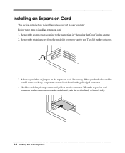
... to the instructions in "Removing the Cover" in your computer. Remove the retaining screw from the metal slot cover you handle the card, be careful not to touch any switches or jumpers on the expansion card, if necessary. Hold the card along the top ...corners and guide it fully. 4-4 Installing and Removing Drives Then lift out the slot cover. 3. When you want to install an expansion card: 1. Follow these steps to use. When the expansion card connector reaches the connector on the circuit board...
... to the instructions in "Removing the Cover" in your computer. Remove the retaining screw from the metal slot cover you handle the card, be careful not to touch any switches or jumpers on the expansion card, if necessary. Hold the card along the top ...corners and guide it fully. 4-4 Installing and Removing Drives Then lift out the slot cover. 3. When you want to install an expansion card: 1. Follow these steps to use. When the expansion card connector reaches the connector on the circuit board...

User Guide
Page 27
Secure the end of the card to the instructions in "Replacing the Cover" in this chapter. Installing and Removing Drives 4-5 Replace the system cover according to the computer with retaining screw. 6. 5. Connect any cables that should be attached to the card. 7.
Secure the end of the card to the instructions in "Replacing the Cover" in this chapter. Installing and Removing Drives 4-5 Replace the system cover according to the computer with retaining screw. 6. 5. Connect any cables that should be attached to the card. 7.

User Guide
Page 28
Installing an Additional Hard Disk Drive Your hard disk drive is installed in it out, as shown below. 4-6 Installing and Removing Drives Follow these steps to the instructions in "Removing the Cover" in this chapter. 2. HDD bracket Hard disk drive 3. Detach all cables from the hard disk drive. Remove the system cover according to install the hard disk drive: 1. You can install one additional hard disk drive in the HDD bracket attached on the chassis. Remove the screw securing the HDD bracket to the chassis and pull it .
Installing an Additional Hard Disk Drive Your hard disk drive is installed in it out, as shown below. 4-6 Installing and Removing Drives Follow these steps to the instructions in "Removing the Cover" in this chapter. 2. HDD bracket Hard disk drive 3. Detach all cables from the hard disk drive. Remove the system cover according to install the hard disk drive: 1. You can install one additional hard disk drive in the HDD bracket attached on the chassis. Remove the screw securing the HDD bracket to the chassis and pull it .
User Guide
Page 30
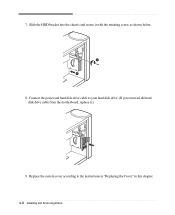
Connect the power and hard disk drive cable to the instructions in "Replacing the Cover" in this chapter. 4-8 Installing and Removing Drives Slide the HDD bracket into the chassis and secure it .) 9. Replace the system cover according to your hard disk drive. (If you removed the hard disk drive cable from the motherboard, replace it with the retaining screw, as shown below. 8. 7.
Connect the power and hard disk drive cable to the instructions in "Replacing the Cover" in this chapter. 4-8 Installing and Removing Drives Slide the HDD bracket into the chassis and secure it .) 9. Replace the system cover according to your hard disk drive. (If you removed the hard disk drive cable from the motherboard, replace it with the retaining screw, as shown below. 8. 7.
User Guide
Page 31
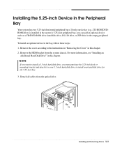
Remove the cover according to install your hard disk drive for the 5.25-inch bay. 3. For more information, see "Installing an Additional Hard Disk Drive" in this chapter. ..., you must purchase the 5.25-inch dock or mounting bracket and attach it to your 3.5-inch hard disk drive to the instructions in "Removing the Cover" in this chapter. 2. Installing the 5.25-inch Device in the bay, follow these steps: 1.
Remove the cover according to install your hard disk drive for the 5.25-inch bay. 3. For more information, see "Installing an Additional Hard Disk Drive" in this chapter. ..., you must purchase the 5.25-inch dock or mounting bracket and attach it to your 3.5-inch hard disk drive to the instructions in "Removing the Cover" in this chapter. 2. Installing the 5.25-inch Device in the bay, follow these steps: 1.
User Guide
Page 32
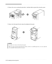
And then slide the optical drive from the chassis by pulling the front panel. Remove the front panel from the system. 5. Remove the screws securing the optical drive. When you remove the front panel from the front panel. 4-10 Installing and Removing Drives 4. NOTES Be careful, not to split the power and LED cables from the chassis, you have to carefully apart the cover not to bent or break the front panel.
And then slide the optical drive from the chassis by pulling the front panel. Remove the front panel from the system. 5. Remove the screws securing the optical drive. When you remove the front panel from the front panel. 4-10 Installing and Removing Drives 4. NOTES Be careful, not to split the power and LED cables from the chassis, you have to carefully apart the cover not to bent or break the front panel.
User Guide
Page 33
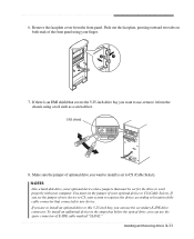
...your finger. 7. If you want to install is set the jumper of the cable connector that must set to CS (Cable Select). Remove the faceplate cover from the chassis using your system recognizes the device according to location of your computer. You must be set the jumper of E-IDE cable marked... "SLAVE." EMI shield 8. If there is an EMI shield that covers the 5.25-inch drive bay you are to install an optional drive to new device. Make sure the jumper of optional drive you can use...
...your finger. 7. If you want to install is set the jumper of the cable connector that must set to CS (Cable Select). Remove the faceplate cover from the chassis using your system recognizes the device according to location of your computer. You must be set the jumper of E-IDE cable marked... "SLAVE." EMI shield 8. If there is an EMI shield that covers the 5.25-inch drive bay you are to install an optional drive to new device. Make sure the jumper of optional drive you can use...

User Guide
Page 36
Replace the system cover according to the chassis. 15. Replace the HDD bracket to the instructions in "Replacing the Cover" in this chapter. 4-14 Installing and Removing Drives 14.
Replace the system cover according to the chassis. 15. Replace the HDD bracket to the instructions in "Replacing the Cover" in this chapter. 4-14 Installing and Removing Drives 14.
User Guide
Page 45
... display resolution or color depth? Use another diskette that the monitor connector is properly and securely connected to the video connector of the diskette to cover the hole. To change the display resolution or color depth, use another diskette or check the diskette by running Check Disk. (For detail information, refer...
... display resolution or color depth? Use another diskette that the monitor connector is properly and securely connected to the video connector of the diskette to cover the hole. To change the display resolution or color depth, use another diskette or check the diskette by running Check Disk. (For detail information, refer...
User Guide
Page 48
...TO INVISIBLE LASER RADIATION. Do not attempt to qualified service personnel. No user-serviceable parts inside of the drive. Do not open the cover. B-2 Approva Statements When the power switch is no hazardous LASER radiation with International Electrotechnical Commission (IEC) Publication 825]. Da der im... à la pluie ou à l'humidité. Caution The laser used in hazardous radiation exposure. Refer servicing to open the top cover of fire or electric shock, do not expose this appliance to look into the inside . Attention Pour reduire les risques de decharges, ne...
...TO INVISIBLE LASER RADIATION. Do not attempt to qualified service personnel. No user-serviceable parts inside of the drive. Do not open the cover. B-2 Approva Statements When the power switch is no hazardous LASER radiation with International Electrotechnical Commission (IEC) Publication 825]. Da der im... à la pluie ou à l'humidité. Caution The laser used in hazardous radiation exposure. Refer servicing to open the top cover of fire or electric shock, do not expose this appliance to look into the inside . Attention Pour reduire les risques de decharges, ne...


