eMachines EL1358 Service Guide
Page 77
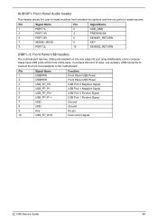
... Name 1 PORT 1L 3 PORT 1R 5 PORT 2R 7 SENSE_SEND 9 PORT 2L Pin Signal Name 2 AUD_GND 4 PRESENCE# 6 SENSE1_RETURN 8 KEY 10 SENSE2_RETURN USBF1~3: Front Panel USB headers The motherboard has two USB ports installed on the rear edge I/O port array.Additionally, some computer cases have USB ports at the front of case, use auxiliary... Panel USB Power USB Port 0 Negative Signal USB Port 1 Negative Signal USB Port 0 Positive Signal USB Port 1 Positive Signal Ground Ground No pin Overcurrent signal EL1358 Service Guide 69
... Name 1 PORT 1L 3 PORT 1R 5 PORT 2R 7 SENSE_SEND 9 PORT 2L Pin Signal Name 2 AUD_GND 4 PRESENCE# 6 SENSE1_RETURN 8 KEY 10 SENSE2_RETURN USBF1~3: Front Panel USB headers The motherboard has two USB ports installed on the rear edge I/O port array.Additionally, some computer cases have USB ports at the front of case, use auxiliary... Panel USB Power USB Port 0 Negative Signal USB Port 1 Negative Signal USB Port 0 Positive Signal USB Port 1 Positive Signal Ground Ground No pin Overcurrent signal EL1358 Service Guide 69
eMachines EL1358 Service Guide
Page 78
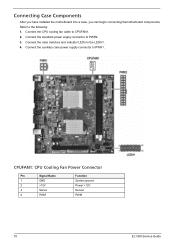
Connect the standard power supply connector to the following: 1. CPUFAN1: CPU Cooling Fan Power Connector Pin Signal Name 1 GND 2 +12V 3 Sense 4 PWM Function System ground Power +12V Sensor PWM 70 EL1358 Service Guide Refer to PWR2. 3. Connect the case switches and indicator LEDs to CPUFAN1. 2. Connecting Case Components After you have installed the motherboard into a case, you can begin connecting themotherboard components. Connect the CPU cooling fan cable to the LEDH1. 4. Connect the auxiliary case power supply connector to PWR1.
Connect the standard power supply connector to the following: 1. CPUFAN1: CPU Cooling Fan Power Connector Pin Signal Name 1 GND 2 +12V 3 Sense 4 PWM Function System ground Power +12V Sensor PWM 70 EL1358 Service Guide Refer to PWR2. 3. Connect the case switches and indicator LEDs to CPUFAN1. 2. Connecting Case Components After you have installed the motherboard into a case, you can begin connecting themotherboard components. Connect the CPU cooling fan cable to the LEDH1. 4. Connect the auxiliary case power supply connector to PWR1.


