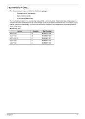
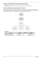
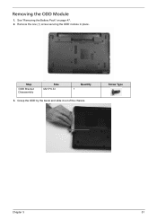
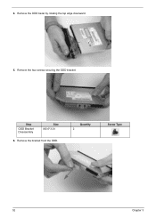
eMachines eME732 Series Service Guide
Page 7
... Password Utilities 39 Removing BIOS Passwords 40 Miscellaneous Utilities 41 Machine Disassembly and Replacement 43 Disassembly Requirements 43 Pre-disassembly Instructions 44 Disassembly Process 45 External Modules Disassembly Process 46 External Modules Disassembly Flowchart 46 Removing the Battery Pack 47 Removing the SD Dummy... Card 48 Removing the Keyboard 49 Removing the ODD Module 51 Main Unit Disassembly Process 53 Main Unit Disassembly Flowchart 53 Removing the Lower Cover 54 Disassembly Overview 56 Removing the DIMM Modules 57 Removing the WLAN Module 58 Removing ...
eMachines eME732 Series Service Guide
Page 8
Table of Contents Removing the CPU 68 Removing the Mainboard 69 Removing the Bluetooth Module 71 LCD Module Disassembly Process 74 LCD Module Disassembly Flowchart 74 Removing the LCD Bezel 75 Removing the Camera (CCD) Module 77 Removing the LCD Panel 78 Remove the LCD Hinges 79 Removing the ...
eMachines eME732 Series Service Guide
Page 53
..., group the screws with the corresponding components to disassemble the notebook computer for the different components vary in size. Disassembly Requirements To disassemble the computer, you need the following tools: • Wrist grounding strap and conductive mat for preventing ...; Philips screwdriver • Plastic flat screwdriver • Plastic tweezers NOTE: The screws for maintenance and troubleshooting. Chapter 3 Machine Disassembly and Replacement IMPORTANT:The outside housing and color may vary from the mass produced model. Chapter 3 43 This chapter contains step-by...
eMachines eME732 Series Service Guide
Page 54
Place the system on a flat, stable surface. 44 Chapter 3 Unplug the AC adapter and all peripherals. 2. Turn off the power to the system and all power and signal cables from the system. 3. Pre-disassembly Instructions Before proceeding with the disassembly procedure, make sure that you do the following: 1.
eMachines eME732 Series Service Guide
Page 55
... is divided into the following stages: • External module disassembly • Main unit disassembly • LCD module disassembly The flowcharts provided in that order. Main Screw List Screw Quantity Part Number M2.5*6.0-I 21 86.A08V7.004 M2.0*3.0-I 20 86.... Chapter 3 45 Observe the order of the sequence to avoid damage to remove the mainboard, you must first remove the keyboard, then disassemble the inside assembly frame in the succeeding disassembly sections illustrate the entire disassembly sequence. For example, if you want to any of the hardware components.
eMachines eME732 Series Service Guide
Page 56
For example, if you must first remove the keyboard, then disassemble the inside assembly frame in that order. Screw List Step ODD Module Disassembly ODD Bracket Disassembly Screw M2.5*6.0-I M2.0*3.0-I Quantity 1 2 Part No. 86.A08V7.004 86.ARE07.002 46 Chapter 3 External Modules Disassembly Flowchart The flowchart below gives you a graphic representation on the entire...
eMachines eME732 Series Service Guide
Page 61
Screw Type Chapter 3 51 Grasp the ODD by the bezel and slide it out of the chassis. See "Removing the Battery Pack" on page 47. 2. Remove the one (1) screw securing the ODD module in place. Step ODD Bracket Disassembly Size M2.5*6.0-I Quantity 1 3. Removing the ODD Module 1.
eMachines eME732 Series Service Guide
Page 62
4. Remove the two screws securing the ODD bracket. Step ODD Bracket Disassembly Size M2.0*3.0-I 6. Remove the ODD bezel by rotating the top edge downward. 5. Remove the bracket from the ODD. Quantity 2 Screw Type 52 Chapter 3
eMachines eME732 Series Service Guide
Page 63
Main Unit Disassembly Process Main Unit Disassembly Flowchart NOTE: Use the process highlighted in red to access the Bluetooth module Chapter 3 53
eMachines eME732 Series Service Guide
Page 64
... callout) Size M2.5*6.0-I M2.0*3.0-I Quantity 18 6 1 1 2 4 1 1 1 Removing the Lower Cover 1. Screw List Step Lower Cover Battery Bay WLAN Module Disassembly USB Module Disassembly HDD Carrier Disassembly LCD Module Disassembly Thermal Module Disassembly Mainboard Disassembly Bluetooth Module Disassembly Screw M2.5*6.0-I M2.0*3.0-I M2.0*3.0-I M2.0*4.0-I.0 M3*0.5+3.5I M2.5*6.0-I M2.0*4.0-I.0 M2.0*4.0-I.0 M2.0*3.0-I Quantity 18 6 Screw Type 54 Chapter 3 See "External Modules...
eMachines eME732 Series Service Guide
Page 66
See "Removing the Lower Cover" on page 56. 2. This section is an overview of the major components of the main unit. 1 23 11 Item 1 2 3 4 5 6 10 9 8 7 65 4 Description VGA heatsink LVDS cable Thermal module WLAN module DIMM module(s) CPU Item 7 8 9 10 11 Description Speaker cable Bluetooth cable RTC battery HDD USB module 56 Chapter 3 Disassembly Overview 1.
eMachines eME732 Series Service Guide
Page 68
Remove the one (1) screw. Disconnect the two (2) cables from the WLAN module. 3. Step WLAN Module Disassembly Size M2.0*3.0-I Quantity 1 Screw Type 58 Chapter 3 See "Disassembly Overview" on page 58. 2. Removing the WLAN Module 1.
eMachines eME732 Series Service Guide
Page 69
Detach and remove the WLAN module from the USB board. Unlock and disconnect the USB FFC from the WLAN socket. 4. See "Disassembly Overview" on page 58. 2. Repeat for the mainboard connector. Removing the USB Board 1. Chapter 3 59
eMachines eME732 Series Service Guide
Page 70
Lift the USB board upward and away from the USB board. Screw Type 60 Chapter 3 Step USB Board Disassembly Size M2.0*4.0-I Quantity 1 4. 3. Remove the one (1) screw from the chassis.
eMachines eME732 Series Service Guide
Page 71
Disconnect the RTC battery cable from the mainboard. Please detach the RTC battery and follow local regulations for disposal. Lift the RTC battery away from the mainboard. 3. Removing the RTC Battery 1. NOTE: The RTC battery has been highlighted with a yellow callout in the previous image. Chapter 3 61 See "Disassembly Overview" on page 58. 2.
eMachines eME732 Series Service Guide
Page 72
Remove the HDD from the bay. 62 Chapter 3 Removing the HDD Module 1. Using the pull-tab, slide the HDD module in the direction of the arrow to disconnect the interface. 3. See "Disassembly Overview" on page 58. 2.
eMachines eME732 Series Service Guide
Page 73
Remove the bracket from the bracket. Remove the two (2) screws from the HDD. 4. Quantity 2 Screw Type Chapter 3 63 Step HDD Carrier Disassembly Size M3*0.5+3.5I 5.
eMachines eME732 Series Service Guide
Page 74
Remove the tape adhering the antenna cables to the mainboard. 3. Unlock and disconnect the LVDS cable. 64 Chapter 3 See "Disassembly Overview" on page 58. 2. Remove the WLAN antennas from the cable guides. 4. Removing the LCD Module 1.
eMachines eME732 Series Service Guide
Page 75
Tilt the upper cover upwards (1) and push down near the hinges to remove it from the left and right hinges. Remove the two (2) screws from the LCD module (2). 2 1 2 7. Step LCD Module Disassembly Size M2.5*6.0-I Quantity 2 Screw Type 6. Lower the upper cover until the it is clear of the LCD module hinges (1) and then pull away to separate it (2). 2 1 Chapter 3 65 5.
eMachines eME732 Series Service Guide
Page 76
Lift the VGA heat sink using the thumb and forefinger to the mainboard. 3. Removing the Thermal Module 1. Loosen the two (2) captive screws connecting the VGA heat sink to remove it from the mainboard. 4. See "Disassembly Overview" on page 58. 2. Disconnect the fan cable as shown. 66 Chapter 3