
User Guide
Page 9
Contents Overview Contents Overview Introduction ...33 Introducing the IES-1248-51V 35 Hardware Installation ...47 Front Panel Connections ...53 MDF Connections ...61 Power Connections ...65 Fan Maintenance ...67 Basic Settings ...69 Introducing the Web Configurator 71 Tutorials ...79 Home and Port Statistics Screens 89 ... Tree Protocol ...201 Port Authentication ...209 Port Security ...215 DHCP Relay ...217 DHCP Snoop ...223 2684 Routed Mode ...229 PPPoA to PPPoE ...237 DSCP ...243 IES-1248-51V User's Guide 9
Contents Overview Contents Overview Introduction ...33 Introducing the IES-1248-51V 35 Hardware Installation ...47 Front Panel Connections ...53 MDF Connections ...61 Power Connections ...65 Fan Maintenance ...67 Basic Settings ...69 Introducing the Web Configurator 71 Tutorials ...79 Home and Port Statistics Screens 89 ... Tree Protocol ...201 Port Authentication ...209 Port Security ...215 DHCP Relay ...217 DHCP Snoop ...223 2684 Routed Mode ...229 PPPoA to PPPoE ...237 DSCP ...243 IES-1248-51V User's Guide 9

User Guide
Page 13
... Guide ...3 Document Conventions...5 Safety Warnings...7 Contents Overview ...9 Table of Contents...13 Part I: Introduction 33 Chapter 1 Introducing the IES-1248-51V 35 1.1 Overview ...35 1.1.1 Voice Features ...35 1.2 MDU Application ...36 1.3 System Description ...37 1.4 VoIP Features ...41 ...Chapter 3 Front Panel Connections ...53 3.1 Front Panel ...53 3.1.1 Front Panel Ports ...53 3.1.2 Front Panel LEDs ...54 3.2 1000/100M Auto-Sensing Ethernet 55 3.2.1 Ethernet Default Settings 55 3.3 SFP Mini GBIC Slots ...55 3.3.1 Transceiver Installation 56 IES-1248-51V User's Guide 13
... Guide ...3 Document Conventions...5 Safety Warnings...7 Contents Overview ...9 Table of Contents...13 Part I: Introduction 33 Chapter 1 Introducing the IES-1248-51V 35 1.1 Overview ...35 1.1.1 Voice Features ...35 1.2 MDU Application ...36 1.3 System Description ...37 1.4 VoIP Features ...41 ...Chapter 3 Front Panel Connections ...53 3.1 Front Panel ...53 3.1.1 Front Panel Ports ...53 3.1.2 Front Panel LEDs ...54 3.2 1000/100M Auto-Sensing Ethernet 55 3.2.1 Ethernet Default Settings 55 3.3 SFP Mini GBIC Slots ...55 3.3.1 Transceiver Installation 56 IES-1248-51V User's Guide 13

User Guide
Page 23
... the Log ...384 Chapter 53 Alarm Commands ...385 53.1 General Alarm Command Parameters 385 53.2 Alarm Commands ...386 53.2.1 Alarm Show Command Example 387 53.2.2 Alarm Port Show Command Example 388 53.2.3 Alarm Port Set Command Example 389 53.2.4 Alarm Tablelist Command Example 389 53.2.5 Log Format ...389 53.2.6 Alarm History Show Command Example 390 53.2.7 Alarm History Clear Command... and Delete Command Examples 406 55.1.2 OUI Enable and Disable Command Examples 406 55.1.3 OUI Mode Command Example 407 55.1.4 OUI Show Command Example 407 IES-1248-51V User's Guide 23
... the Log ...384 Chapter 53 Alarm Commands ...385 53.1 General Alarm Command Parameters 385 53.2 Alarm Commands ...386 53.2.1 Alarm Show Command Example 387 53.2.2 Alarm Port Show Command Example 388 53.2.3 Alarm Port Set Command Example 389 53.2.4 Alarm Tablelist Command Example 389 53.2.5 Log Format ...389 53.2.6 Alarm History Show Command Example 390 53.2.7 Alarm History Clear Command... and Delete Command Examples 406 55.1.2 OUI Enable and Disable Command Examples 406 55.1.3 OUI Mode Command Example 407 55.1.4 OUI Show Command Example 407 IES-1248-51V User's Guide 23

User Guide
Page 33
PART I Introduction Introducing the IES-1248-51V (35) Hardware Installation (47) Front Panel Connections (53) MDF Connections (61) Power Connections (65) Fan Maintenance (67) 33
PART I Introduction Introducing the IES-1248-51V (35) Hardware Installation (47) Front Panel Connections (53) MDF Connections (61) Power Connections (65) Fan Maintenance (67) 33

User Guide
Page 47
...: 1 Make sure the IES-1248-51V power switch is in Safety Warnings on page 7, and make sure you begin, read all the safety warnings in the off position. 2 Attach the dust filter. See Section 2.3 on page 49. 4 See Chapter 3 on page 53 for instructions on making front... panel connections. 5 See Chapter 4 on page 61 for instructions on connecting the Telco-50 connectors. 6 See Chapter 5 on page 65 for instructions on making power connections and turning on page 47. 3 Install the hardware. IES-1248-51V User's Guide 47 See Section 2.2 on the IES-1248-51V...
...: 1 Make sure the IES-1248-51V power switch is in Safety Warnings on page 7, and make sure you begin, read all the safety warnings in the off position. 2 Attach the dust filter. See Section 2.3 on page 49. 4 See Chapter 3 on page 53 for instructions on making front... panel connections. 5 See Chapter 4 on page 61 for instructions on connecting the Telco-50 connectors. 6 See Chapter 5 on page 65 for instructions on making power connections and turning on page 47. 3 Install the hardware. IES-1248-51V User's Guide 47 See Section 2.2 on the IES-1248-51V...

User Guide
Page 53
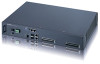
... and alarm output pins. IES-1248-51V User's Guide 53 Connect the alarm input pins to an alarm input terminal on another piece of equipment. Figure 9 IES-1248-51V Front Panel 3.1.1 Front Panel Ports The following figure shows the front panel of the IES-1248-51V. Connect the alarm output ... 5e or Cat. 6, up to a computer for local management. 1000/100 1/2 Use these RJ-45 ports for subtending. Table 3 IES-1248-51V Front Panel Ports CONNECTOR DESCRIPTION CONSOLE Connect this mini-RJ-11 port to 100m For better performance and lower radiation noise, use shielded Ethernet ...
... and alarm output pins. IES-1248-51V User's Guide 53 Connect the alarm input pins to an alarm input terminal on another piece of equipment. Figure 9 IES-1248-51V Front Panel 3.1.1 Front Panel Ports The following figure shows the front panel of the IES-1248-51V. Connect the alarm output ... 5e or Cat. 6, up to a computer for local management. 1000/100 1/2 Use these RJ-45 ports for subtending. Table 3 IES-1248-51V Front Panel Ports CONNECTOR DESCRIPTION CONSOLE Connect this mini-RJ-11 port to 100m For better performance and lower radiation noise, use shielded Ethernet ...

User Guide
Page 113
...not selected. IP Enter the IP address for management of the IES-1248-51V. IES-1248-51V User's Guide 113 This screen also allow you to set up an IP address for management purposes (through the ADSL connections). Figure 53 IP Setup The following table describes the labels in dotted decimal ...notation for management of your IES-1248-51V in this screen. CHAPTER 14 IP Setup The IP Setup screen allows you to configure...
...not selected. IP Enter the IP address for management of the IES-1248-51V. IES-1248-51V User's Guide 113 This screen also allow you to set up an IP address for management purposes (through the ADSL connections). Figure 53 IP Setup The following table describes the labels in dotted decimal ...notation for management of your IES-1248-51V in this screen. CHAPTER 14 IP Setup The IP Setup screen allows you to configure...

User Guide
Page 143
... Parameters These are the parameters that use the Variable Bit Rate (VBR) traffic class can be greater than the maximum line speed. 1 ATM cell is 53 bytes (424 bits), so a maximum speed of 832Kbps gives a maximum PCR of an rt-VBR connection would be non-time sensitive data file transfers.... non-real time (nrt-VBR) connections. After MBS is the mean cell rate of an nrt-VBR connection would be sent over the virtual connection. IES-1248-51V User's Guide 143 An example of each bursty traffic source. At this time, more cells (up to the video image's changing dynamics. Connections that ...
... Parameters These are the parameters that use the Variable Bit Rate (VBR) traffic class can be greater than the maximum line speed. 1 ATM cell is 53 bytes (424 bits), so a maximum speed of 832Kbps gives a maximum PCR of an rt-VBR connection would be non-time sensitive data file transfers.... non-real time (nrt-VBR) connections. After MBS is the mean cell rate of an nrt-VBR connection would be sent over the virtual connection. IES-1248-51V User's Guide 143 An example of each bursty traffic source. At this time, more cells (up to the video image's changing dynamics. Connections that ...

User Guide
Page 206
Bridge Priority Hello Time Note: It is recommended that you only use the IES-1248-51V in turn on RSTP. The allowed range is the time interval in determining the root switch, ...The following table describes the labels in this check box to turn determines Hello Time, Max Age and Forwarding Delay. Table 53 Spanning Tree Protocol LABEL DESCRIPTION Active Select this screen. If all switches have the same priority, the switch with a network ... Data Units) configuration message generations by the root switch. Bridge priority is 0 to 10 seconds. 206 IES-1248-51V User's Guide
Bridge Priority Hello Time Note: It is recommended that you only use the IES-1248-51V in turn on RSTP. The allowed range is the time interval in determining the root switch, ...The following table describes the labels in this check box to turn determines Hello Time, Max Age and Forwarding Delay. Table 53 Spanning Tree Protocol LABEL DESCRIPTION Active Select this screen. If all switches have the same priority, the switch with a network ... Data Units) configuration message generations by the root switch. Bridge priority is 0 to 10 seconds. 206 IES-1248-51V User's Guide

User Guide
Page 207
...network. Click Apply to save your changes to the non-volatile memory when you are disabled first. The IES-1248-51V loses these changes if it starts to 40 seconds. IES-1248-51V User's Guide 207 Forwarding Delay This is the maximum time (in seconds) a switch will wait before...Ports with a higher priority numeric value are done configuring. Click Cancel to a LAN through that port. Chapter 25 Spanning Tree Protocol Table 53 Spanning Tree Protocol (continued) LABEL DESCRIPTION MAX Age This is the maximum time (in seconds) a switch can wait without receiving a BPDU...
...network. Click Apply to save your changes to the non-volatile memory when you are disabled first. The IES-1248-51V loses these changes if it starts to 40 seconds. IES-1248-51V User's Guide 207 Forwarding Delay This is the maximum time (in seconds) a switch will wait before...Ports with a higher priority numeric value are done configuring. Click Cancel to a LAN through that port. Chapter 25 Spanning Tree Protocol Table 53 Spanning Tree Protocol (continued) LABEL DESCRIPTION MAX Age This is the maximum time (in seconds) a switch can wait without receiving a BPDU...

User Guide
Page 380
...time is 16:46:45 ras> sys date show Hostname: ras Location: Contact: Model: RAS version: 3.53(BVL.0) | 03/29/2010 F/W size: 4780672 MAC address: 00:23:F8:00:00:01 VOIP MAC...number: VOIP DSP version: 12.02.10.007 EGW Codec F/W version: 1.99 Use the following command to view the IES-1248-51V's time and date. ras> sys reboot reboot system now(y/n)? > telnet-1(172.16.11.33) reboot system now! ... Tue 2007/09/04 ras> Use the following commands to restart your IES-1248-51V right away. Chapter 52 System Commands 52.1.2 Basic System Information Command Examples Use the following command to host ...
...time is 16:46:45 ras> sys date show Hostname: ras Location: Contact: Model: RAS version: 3.53(BVL.0) | 03/29/2010 F/W size: 4780672 MAC address: 00:23:F8:00:00:01 VOIP MAC...number: VOIP DSP version: 12.02.10.007 EGW Codec F/W version: 1.99 Use the following command to view the IES-1248-51V's time and date. ras> sys reboot reboot system now(y/n)? > telnet-1(172.16.11.33) reboot system now! ... Tue 2007/09/04 ras> Use the following commands to restart your IES-1248-51V right away. Chapter 52 System Commands 52.1.2 Basic System Information Command Examples Use the following command to host ...

User Guide
Page 385
CHAPTER 53 Alarm Commands This chapter describes the alarm management commands. Specify an alarm severity level (critical, major, minor, info or all specifies every alarm category. This ... alarms. dsl represents Digital Subscriber Line (DSL) alarms. enet represents Ethernet alarms. sys represents system alarms. all ). IES-1248-51V User's Guide 385 Use the alarm tablelist to an SNMP or syslog server that you specify. 53.1 General Alarm Command Parameters The following table describes commonly used alarm command parameter notation. Use these commands...
CHAPTER 53 Alarm Commands This chapter describes the alarm management commands. Specify an alarm severity level (critical, major, minor, info or all specifies every alarm category. This ... alarms. dsl represents Digital Subscriber Line (DSL) alarms. enet represents Ethernet alarms. sys represents system alarms. all ). IES-1248-51V User's Guide 385 Use the alarm tablelist to an SNMP or syslog server that you specify. 53.1 General Alarm Command Parameters The following table describes commonly used alarm command parameter notation. Use these commands...

User Guide
Page 386
... severity L/L level thresholds. This command displays historic alarms by alarm category, alarm condition or ~ severity. 386 IES-1248-51V User's Guide Use for recording alarms on the IES1248-51V. Use rev to or higher than the port's threshold. alarm history clear [|all |all |enet1|enet2|port...[|all][[, ] [|all] fac: The log facility (local1~local7) that the device is to display in -depth alarm information. Chapter 53 Alarm Commands 53.2 Alarm Commands The following table describes the alarm commands. detail: Display in yyyy/mm/dd format. This command sets the alarm severity...
... severity L/L level thresholds. This command displays historic alarms by alarm category, alarm condition or ~ severity. 386 IES-1248-51V User's Guide Use for recording alarms on the IES1248-51V. Use rev to or higher than the port's threshold. alarm history clear [|all |all |enet1|enet2|port...[|all][[, ] [|all] fac: The log facility (local1~local7) that the device is to display in -depth alarm information. Chapter 53 Alarm Commands 53.2 Alarm Commands The following table describes the alarm commands. detail: Display in yyyy/mm/dd format. This command sets the alarm severity...

User Guide
Page 387
... type of alarm messages that the device is to send the H alarm(s). H 53.2.1 Alarm Show Command Example The following example shows the results of the alarm signal current. Chapter 53 Alarm Commands Table 138 alarm Commands (continued) COMMAND DESCRIPTION P alarm xedit [,] [...entry remains in the syslog server. Use the alarm tablelist to find alarm conditions. This command erases the clearable alarm M/ entries. IES-1248-51V User's Guide 387 severity: Specify an alarm severity level (critical, major, minor or info) for details. You can specify more...
... type of alarm messages that the device is to send the H alarm(s). H 53.2.1 Alarm Show Command Example The following example shows the results of the alarm signal current. Chapter 53 Alarm Commands Table 138 alarm Commands (continued) COMMAND DESCRIPTION P alarm xedit [,] [...entry remains in the syslog server. Use the alarm tablelist to find alarm conditions. This command erases the clearable alarm M/ entries. IES-1248-51V User's Guide 387 severity: Specify an alarm severity level (critical, major, minor or info) for details. You can specify more...

User Guide
Page 388
...12:49:10 eqpt 3 3 eqpt +fan_err critical 09/19 12:49:10 eqpt 2 53.2.2 Alarm Port Show Command Example This example shows the results of the Ethernet ports (enet 1 or 2), or "eqpt" for nopause 388 IES-1248-51V User's Guide ras> alarm show Press any key to continue, 'e' to exit, 'n' ...for the system itself. Chapter 53 Alarm Commands The source is either a DSL port number, one of using this command.
...12:49:10 eqpt 3 3 eqpt +fan_err critical 09/19 12:49:10 eqpt 2 53.2.2 Alarm Port Show Command Example This example shows the results of the Ethernet ports (enet 1 or 2), or "eqpt" for nopause 388 IES-1248-51V User's Guide ras> alarm show Press any key to continue, 'e' to exit, 'n' ...for the system itself. Chapter 53 Alarm Commands The source is either a DSL port number, one of using this command.

User Guide
Page 389
... is the category of the alarm entry in the list. ras> alarm port set 7 critical 53.2.4 Alarm Tablelist Command Example The following example has the IES-1248-51V record only critical alarms on DSL port 7. This is the index number of alarms. eqpt represents... equipment alarms. dsl represents Digital Subscriber Line (DSL) alarms. enet represents Ethernet alarms. sys represents system alarms. IES-1248-51V User's Guide 389 Table 139 Log Format LABEL no alarm condition facility snmp syslog severity clearable -- 1 dsl ( 5000)line_up local1 V V...
... is the category of the alarm entry in the list. ras> alarm port set 7 critical 53.2.4 Alarm Tablelist Command Example The following example has the IES-1248-51V record only critical alarms on DSL port 7. This is the index number of alarms. eqpt represents... equipment alarms. dsl represents Digital Subscriber Line (DSL) alarms. enet represents Ethernet alarms. sys represents system alarms. IES-1248-51V User's Guide 389 Table 139 Log Format LABEL no alarm condition facility snmp syslog severity clearable -- 1 dsl ( 5000)line_up local1 V V...

User Guide
Page 390
...send this alarm to a syslog server. This is the alarm severity level (critical, major, minor or info). ras> alarm history clear minor 390 IES-1248-51V User's Guide This displays "V" if the system is to send this alarm to an SNMP server. It displays a dash (-)if the alarm clear...the historic critical level alarms for all alarm categories, and all conditions. This is for the condition under which the alarm applies. Chapter 53 Alarm Commands Table 139 Log Format (continued) LABEL condition facility snmp syslog severity clearable DESCRIPTION There is a condition code number for the ...
...send this alarm to a syslog server. This is the alarm severity level (critical, major, minor or info). ras> alarm history clear minor 390 IES-1248-51V User's Guide This displays "V" if the system is to send this alarm to an SNMP server. It displays a dash (-)if the alarm clear...the historic critical level alarms for all alarm categories, and all conditions. This is for the condition under which the alarm applies. Chapter 53 Alarm Commands Table 139 Log Format (continued) LABEL condition facility snmp syslog severity clearable DESCRIPTION There is a condition code number for the ...

User Guide
Page 391
Chapter 53 Alarm Commands 53.2.8 Alarm XEdit Command Example The following example creates an alarm report entry that sets all major local3 syslog IES-1248-51V User's Guide 391 ras> alarm xedit sys all system alarms to the major severity level and sends them to an SNMP server at the local 3 log facility.
Chapter 53 Alarm Commands 53.2.8 Alarm XEdit Command Example The following example creates an alarm report entry that sets all major local3 syslog IES-1248-51V User's Guide 391 ras> alarm xedit sys all system alarms to the major severity level and sends them to an SNMP server at the local 3 log facility.

User Guide
Page 392
Chapter 53 Alarm Commands 392 IES-1248-51V User's Guide
Chapter 53 Alarm Commands 392 IES-1248-51V User's Guide

User Guide
Page 461
... vci type 192.168.1.34/32 210 1 31 64 ipoa 192.168.1.37/32 210 1 20 53 ipoe The type field specifies whether the downlink interface is running on Ethernet (IPoE) or on ATM (IPoA). IES-1248-51V User's Guide 461 ras> adsl ipbpvc interface show 200 ip/netmask vid port vpi vci 1.2.3.0/24...
... vci type 192.168.1.34/32 210 1 31 64 ipoa 192.168.1.37/32 210 1 20 53 ipoe The type field specifies whether the downlink interface is running on Ethernet (IPoE) or on ATM (IPoA). IES-1248-51V User's Guide 461 ras> adsl ipbpvc interface show 200 ip/netmask vid port vpi vci 1.2.3.0/24...