
User Guide
Page 3
... Contents ...3 Chapter 1 Getting to Know Your Switch...5 1.1 Introduction ...5 1.1.1 Bridging Example ...5 1.1.2 High Performance Switching Example 6 1.1.3 Gigabit Ethernet to the Desktop 7 1.1.4 IEEE 802.1Q VLAN Application Example 7 1.1.5 IPv6 Support ...8 1.2 Ways to Manage the Switch ...8 1.3 Good Habits for Managing the Switch 8 Chapter 2 Hardware Installation and Connection 11 ... The Web Configurator ...25 4.1 Introduction ...25 4.2 System Login ...25 4.3 The Web Configurator Layout ...26 4.3.1 Change Your Password ...32 4.4 Switch Lockout ...32 GS1910/XGS1910 Series User's Guide 3
... Contents ...3 Chapter 1 Getting to Know Your Switch...5 1.1 Introduction ...5 1.1.1 Bridging Example ...5 1.1.2 High Performance Switching Example 6 1.1.3 Gigabit Ethernet to the Desktop 7 1.1.4 IEEE 802.1Q VLAN Application Example 7 1.1.5 IPv6 Support ...8 1.2 Ways to Manage the Switch ...8 1.3 Good Habits for Managing the Switch 8 Chapter 2 Hardware Installation and Connection 11 ... The Web Configurator ...25 4.1 Introduction ...25 4.2 System Login ...25 4.3 The Web Configurator Layout ...26 4.3.1 Change Your Password ...32 4.4 Switch Lockout ...32 GS1910/XGS1910 Series User's Guide 3
User Guide
Page 4
...Out of the Web Configurator 32 4.6 Help ...32 Chapter 5 Tutorials ...33 5.1 How to Change Switch Management IP Address 33 5.2 How to Configure Login Accounts and Privilege Levels 34 5.3 How to Manage...to Use IP Source Guard and DHCP Snooping to Prevent Spoofed Traffic 45 5.8 How to Use DHCP Relay on the Switch 48 5.8.1 Creating a VLAN ...49 5.8.2 Configuring DHCP Relay ...49 5.8.3 Troubleshooting ...50 5.9 How to Use Link ... Use IGMP Snooping to Reduce Multicast Traffic Passing through your Switch 60 5.12 How to Configure Access Control List (ACL) for Packets Filtering 63 5.13 How to ...
...Out of the Web Configurator 32 4.6 Help ...32 Chapter 5 Tutorials ...33 5.1 How to Change Switch Management IP Address 33 5.2 How to Configure Login Accounts and Privilege Levels 34 5.3 How to Manage...to Use IP Source Guard and DHCP Snooping to Prevent Spoofed Traffic 45 5.8 How to Use DHCP Relay on the Switch 48 5.8.1 Creating a VLAN ...49 5.8.2 Configuring DHCP Relay ...49 5.8.3 Troubleshooting ...50 5.9 How to Use Link ... Use IGMP Snooping to Reduce Multicast Traffic Passing through your Switch 60 5.12 How to Configure Access Control List (ACL) for Packets Filtering 63 5.13 How to ...
User Guide
Page 5
...users that need to the corporate backbone. The Ethernet ports on the GS1910-24HP or GS1910-48HP are done on the master switch, which then maintains and manages the slave switches in web configurator, managing and configuring the Switch is stackable and provides two or four SFP+ slots for a miniGBIC... 48 10/100/1000 Mbps Ethernet ports. CHAPTER 1 Getting to eight XGS1910-24 or XGS1910-48 switches per Ethernet port. With its built-in the stack. The GS1910-24, GS1910-24HP, XGS1910-24 or XGS1910-48 also has four GbE dual personality interfaces. A dual personality interface includes...
...users that need to the corporate backbone. The Ethernet ports on the GS1910-24HP or GS1910-48HP are done on the master switch, which then maintains and manages the slave switches in web configurator, managing and configuring the Switch is stackable and provides two or four SFP+ slots for a miniGBIC... 48 10/100/1000 Mbps Ethernet ports. CHAPTER 1 Getting to eight XGS1910-24 or XGS1910-48 switches per Ethernet port. With its built-in the stack. The GS1910-24, GS1910-24HP, XGS1910-24 or XGS1910-48 also has four GbE dual personality interfaces. A dual personality interface includes...
User Guide
Page 6
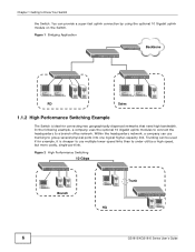
... a high-speed, but more costly, single-port link. Trunking can provide a super-fast uplink connection by using the optional 10 Gigabit uplink module on the Switch. Figure 2 High Performance Switching 10 Gbps Branch Trunk HQ 6 GS1910/XGS1910 Series User's Guide Figure 1 Bridging Application Backbone RD Sales 1.1.2 High Performance...
... a high-speed, but more costly, single-port link. Trunking can provide a super-fast uplink connection by using the optional 10 Gigabit uplink module on the Switch. Figure 2 High Performance Switching 10 Gbps Branch Trunk HQ 6 GS1910/XGS1910 Series User's Guide Figure 1 Bridging Application Backbone RD Sales 1.1.2 High Performance...
User Guide
Page 7
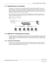
The uplink module supports a fiber-optic connection which demand high bandwidth for a group of copper cabling. GS1910/XGS1910 Series User's Guide 7 Use the optional 10 Gigabit uplink module to provide high speed access to be modified at any time by reducing ...broadcast traffic. To expand the network, simply add more networking devices such as switches, routers, computers, print servers and so on a logical network belong to one or more groups. Stations on . VLAN groups can be partitioned into multiple ...
The uplink module supports a fiber-optic connection which demand high bandwidth for a group of copper cabling. GS1910/XGS1910 Series User's Guide 7 Use the optional 10 Gigabit uplink module to provide high speed access to be modified at any time by reducing ...broadcast traffic. To expand the network, simply add more networking devices such as switches, routers, computers, print servers and so on a logical network belong to one or more groups. Stations on . VLAN groups can be partitioned into multiple ...
User Guide
Page 8
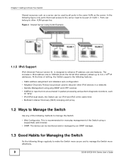
... to be monitored and/or managed by all ports in a network) • Remote Management using a (supported) web browser. • SNMP. the Switch can belong to manage the Switch more effectively. 8 GS1910/XGS1910 Series User's Guide In the following features. • Static address assignment and stateless auto-configuration • Neighbor Discovery Protocol (a protocol used...
... to be monitored and/or managed by all ports in a network) • Remote Management using a (supported) web browser. • SNMP. the Switch can belong to manage the Switch more effectively. 8 GS1910/XGS1910 Series User's Guide In the following features. • Static address assignment and stateless auto-configuration • Neighbor Discovery Protocol (a protocol used...

User Guide
Page 9
If you forget your last configuration. If you backed up the configuration (and make sure you would not have to reset the Switch to restore it). Restoring an earlier working configuration may be useful if the device becomes unstable or even crashes. Use a password that's ... put it in a safe place. • Back up an earlier configuration file, you know how to its factory default settings. GS1910/XGS1910 Series User's Guide 9 You could simply restore your password, you will have to Know Your Switch • Change the password. Chapter 1 Getting to totally re-configure the...
If you forget your last configuration. If you backed up the configuration (and make sure you would not have to reset the Switch to restore it). Restoring an earlier working configuration may be useful if the device becomes unstable or even crashes. Use a password that's ... put it in a safe place. • Back up an earlier configuration file, you know how to its factory default settings. GS1910/XGS1910 Series User's Guide 9 You could simply restore your password, you will have to Know Your Switch • Change the password. Chapter 1 Getting to totally re-configure the...

User Guide
Page 10
Chapter 1 Getting to Know Your Switch 10 GS1910/XGS1910 Series User's Guide
Chapter 1 Getting to Know Your Switch 10 GS1910/XGS1910 Series User's Guide
User Guide
Page 11
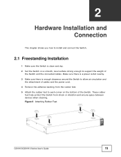
Figure 5 Attaching Rubber Feet GS1910/XGS1910 Series User's Guide 11 CHAPTER 2 Hardware Installation and Connection This chapter shows you how to install and connect the Switch. 2.1 Freestanding Installation 1 Make sure the Switch is enough clearance around the Switch to allow air circulation and the attachment of cables ... or vibration and ensure space between devices when stacking. These rubber feet help protect the Switch from the rubber feet. 5 Attach the rubber feet to support the weight of the Switch. Make sure there is a power outlet nearby. 3 Make sure there is clean and...
Figure 5 Attaching Rubber Feet GS1910/XGS1910 Series User's Guide 11 CHAPTER 2 Hardware Installation and Connection This chapter shows you how to install and connect the Switch. 2.1 Freestanding Installation 1 Make sure the Switch is enough clearance around the Switch to allow air circulation and the attachment of cables ... or vibration and ensure space between devices when stacking. These rubber feet help protect the Switch from the rubber feet. 5 Attach the rubber feet to support the weight of the Switch. Make sure there is a power outlet nearby. 3 Make sure there is clean and...
User Guide
Page 12
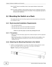
... of all necessary precautions to anchor the rack securely before installing the unit. 2.2.2 Attaching the Mounting Brackets to the Switch 1 Position a mounting bracket on one side of the Switch does not make the rack unstable or topheavy. Take all the equipment it contains. • Make sure the position... Philips screwdriver. • Four M5 flat head screws and a #2 Philips screwdriver. Leave space between devices when stacking. Figure 6 Attaching the Mounting Brackets 12 GS1910/XGS1910 Series User's Guide This is especially important for enclosed rack installations. 2.2 Mounting the...
... of all necessary precautions to anchor the rack securely before installing the unit. 2.2.2 Attaching the Mounting Brackets to the Switch 1 Position a mounting bracket on one side of the Switch does not make the rack unstable or topheavy. Take all the equipment it contains. • Make sure the position... Philips screwdriver. • Four M5 flat head screws and a #2 Philips screwdriver. Leave space between devices when stacking. Figure 6 Attaching the Mounting Brackets 12 GS1910/XGS1910 Series User's Guide This is especially important for enclosed rack installations. 2.2 Mounting the...

User Guide
Page 13
GS1910/XGS1910 Series User's Guide 13 Proceed to the next section. 2.2.3 Mounting the Switch on a Rack 1 Position a mounting bracket (that is already attached to the Switch) on one side of the rack, lining up the two screw holes on the bracket with the screw holes on the side of the rack.... Figure 7 Mounting the Switch on a Rack 2 Using a #2 Philips screwdriver, install the M5 flat head screws through the mounting bracket holes into the rack. 3 Repeat steps 1 and 2 to attach ...
GS1910/XGS1910 Series User's Guide 13 Proceed to the next section. 2.2.3 Mounting the Switch on a Rack 1 Position a mounting bracket (that is already attached to the Switch) on one side of the rack, lining up the two screw holes on the bracket with the screw holes on the side of the rack.... Figure 7 Mounting the Switch on a Rack 2 Using a #2 Philips screwdriver, install the M5 flat head screws through the mounting bracket holes into the rack. 3 Repeat steps 1 and 2 to attach ...
User Guide
Page 15
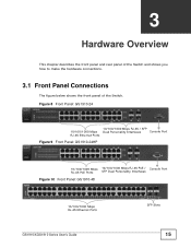
...45 Ethernet Ports Figure 9 Front Panel: GS1910-24HP 10/100/1000 Mbps RJ-45 PoE Ports 10/100/1000 Mbps RJ-45 PoE / SFP Dual Personality Interfaces Console Port Figure 10 Front Panel: GS1910-48 10/100/1000 Mbps RJ-45 Ethernet Ports GS1910/XGS1910 Series User's Guide SFP Slots ...15 CHAPTER 3 Hardware Overview This chapter describes the front panel and rear panel of the Switch and shows you how to make the hardware connections....
...45 Ethernet Ports Figure 9 Front Panel: GS1910-24HP 10/100/1000 Mbps RJ-45 PoE Ports 10/100/1000 Mbps RJ-45 PoE / SFP Dual Personality Interfaces Console Port Figure 10 Front Panel: GS1910-48 10/100/1000 Mbps RJ-45 Ethernet Ports GS1910/XGS1910 Series User's Guide SFP Slots ...15 CHAPTER 3 Hardware Overview This chapter describes the front panel and rear panel of the Switch and shows you how to make the hardware connections....

User Guide
Page 16
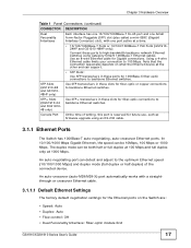
...DESCRIPTION Connect these ports to a computer, a hub, an Ethernet switch or router. 10/100/1000 Mbps RJ-45 PoE Ports (GS191024HP and GS1910-48HP only) Connect these ports to a computer, a hub, an Ethernet switch or router. 16 GS1910/XGS1910 Series User's Guide Chapter 3 Hardware Overview Figure 11 Front ...Panel: GS1910-48HP 10/100/1000 Mbps RJ-45 PoE Ports Figure 12...
...DESCRIPTION Connect these ports to a computer, a hub, an Ethernet switch or router. 10/100/1000 Mbps RJ-45 PoE Ports (GS191024HP and GS1910-48HP only) Connect these ports to a computer, a hub, an Ethernet switch or router. 16 GS1910/XGS1910 Series User's Guide Chapter 3 Hardware Overview Figure 11 Front ...Panel: GS1910-48HP 10/100/1000 Mbps RJ-45 PoE Ports Figure 12...
User Guide
Page 17
... reserved for Gigabit connections. Note that the connection speed also depends on the Switch are: • Speed: Auto • Duplex: Auto • Flow control: Off • Dual Personality Interface: Fiber-optic module first GS1910/XGS1910 Series User's Guide 17 Console Port At the time of the connected ...full duplex only at the other end can be 10Mbps, 100 Mbps or 1000 Mbps. SFP Slots (GS1910-48 and GS191048HP only) Use SFP transceivers in these ports to backbone Ethernet switches. In 10/100/1000 Mbps Gigabit Ethernet, the speed can detect and adjust to 100 Mbps. ...
... reserved for Gigabit connections. Note that the connection speed also depends on the Switch are: • Speed: Auto • Duplex: Auto • Flow control: Off • Dual Personality Interface: Fiber-optic module first GS1910/XGS1910 Series User's Guide 17 Console Port At the time of the connected ...full duplex only at the other end can be 10Mbps, 100 Mbps or 1000 Mbps. SFP Slots (GS1910-48 and GS191048HP only) Use SFP transceivers in these ports to backbone Ethernet switches. In 10/100/1000 Mbps Gigabit Ethernet, the speed can detect and adjust to 100 Mbps. ...

User Guide
Page 18
... committee's INF-8074i specification Rev 1.0 for Small Form-Factor Pluggable (SFP) or SFP+ transceivers. A transceiver is operating. The Switch does not come with the Small Form-Factor Pluggable (SFP) Transceiver MultiSource Agreement (MSA). You can connect either to install a transceiver... (SFP or SFP+ module). 18 GS1910/XGS1910 Series User's Guide Use a transceiver to connect a fiberoptic cable to as a mini-GBIC. You can change transceivers while the Switch is a single unit that comply with transceivers. Chapter 3 Hardware Overview...
... committee's INF-8074i specification Rev 1.0 for Small Form-Factor Pluggable (SFP) or SFP+ transceivers. A transceiver is operating. The Switch does not come with the Small Form-Factor Pluggable (SFP) Transceiver MultiSource Agreement (MSA). You can connect either to install a transceiver... (SFP or SFP+ module). 18 GS1910/XGS1910 Series User's Guide Use a transceiver to connect a fiberoptic cable to as a mini-GBIC. You can change transceivers while the Switch is a single unit that comply with transceivers. Chapter 3 Hardware Overview...

User Guide
Page 19
... the slot with the exposed section of PCB board facing down. Figure 16 Opening the Transceiver's Latch Example GS1910/XGS1910 Series User's Guide 19 Chapter 3 Hardware Overview 1 Insert the transceiver into place. 3 The Switch automatically detects the installed transceiver. Figure 14 Transceiver Installation Example 2 Press the transceiver firmly until it is functioning...
... the slot with the exposed section of PCB board facing down. Figure 16 Opening the Transceiver's Latch Example GS1910/XGS1910 Series User's Guide 19 Chapter 3 Hardware Overview 1 Insert the transceiver into place. 3 The Switch automatically detects the installed transceiver. Figure 14 Transceiver Installation Example 2 Press the transceiver firmly until it is functioning...
User Guide
Page 20
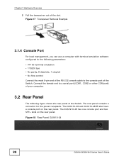
...The XGS1910-48 has one console port and two SFP+ slots on the rear panel. The GS1910-48 and GS1910-48HP also have a console port on the rear panel. Figure 18 Rear Panel: GS1910-24 20 GS1910/XGS1910 Series User's Guide Connect the female end to a serial port (COM1, COM2 or other...the male 9-pin end of the RS-232 console cable to the following figure shows the rear panel of the Switch. Chapter 3 Hardware Overview 2 Pull the transceiver out of the Switch. The rear panel contains a connector for the power receptacle. Figure 17 Transceiver Removal Example 3.1.4 Console Port For local...
...The XGS1910-48 has one console port and two SFP+ slots on the rear panel. The GS1910-48 and GS1910-48HP also have a console port on the rear panel. Figure 18 Rear Panel: GS1910-24 20 GS1910/XGS1910 Series User's Guide Connect the female end to a serial port (COM1, COM2 or other...the male 9-pin end of the RS-232 console cable to the following figure shows the rear panel of the Switch. Chapter 3 Hardware Overview 2 Pull the transceiver out of the Switch. The rear panel contains a connector for the power receptacle. Figure 17 Transceiver Removal Example 3.1.4 Console Port For local...
User Guide
Page 21
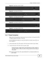
... of your Switch. 2 Connect the other end of the fans. Note: Use only power wires of the required diameter for turning on the panel and that no objects obstruct the airflow of the cord to a power supply. Figure 19 Rear Panel: GS1910-24HP Figure 20 Front Panel: GS1910-48 Figure ...21 Front Panel: GS1910-48HP Figure 22 Front Panel: XGS1910-24 Figure 23 Front Panel: XGS1910-48 Chapter 3 Hardware Overview 3.2.1 Power Connector ...
... of your Switch. 2 Connect the other end of the fans. Note: Use only power wires of the required diameter for turning on the panel and that no objects obstruct the airflow of the cord to a power supply. Figure 19 Rear Panel: GS1910-24HP Figure 20 Front Panel: GS1910-48 Figure ...21 Front Panel: GS1910-48HP Figure 22 Front Panel: XGS1910-24 Figure 23 Front Panel: XGS1910-48 Chapter 3 Hardware Overview 3.2.1 Power Connector ...
User Guide
Page 22
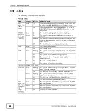
... 10/100/1000 Mbps RJ-45 Ports LNK/ACT Green Blinking Amber On Blinking On Off PoE Green On (GS1910- 24HP and GS1910- The Switch is acting as the master in stacking. The Switch is acting as a slave member in stacking and is down. The system is rebooting and performing self-diagnostic tests... Ethernet port's LED is acting as the backup master device in stacking. The Switch is changed back to act as a PoE LED by using the LED MODE button on . The system is no power supplied. 22 GS1910/XGS1910 Series User's Guide Power supplied to /from a 10/1000 Mbps Ethernet ...
... 10/100/1000 Mbps RJ-45 Ports LNK/ACT Green Blinking Amber On Blinking On Off PoE Green On (GS1910- 24HP and GS1910- The Switch is acting as the master in stacking. The Switch is acting as a slave member in stacking and is down. The system is rebooting and performing self-diagnostic tests... Ethernet port's LED is acting as the backup master device in stacking. The Switch is changed back to act as a PoE LED by using the LED MODE button on . The system is no power supplied. 22 GS1910/XGS1910 Series User's Guide Power supplied to /from a 10/1000 Mbps Ethernet ...
User Guide
Page 25
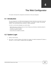
CHAPTER 4 The Web Configurator This section introduces the configuration and functions of the Switch (for example, the default management IP address is 192.168.1.1) in Windows XP SP (Service Pack) 2. • JavaScript (enabled by default). • Java permissions ...://" and the IP address of the web configurator. 4.1 Introduction The web configurator is an HTML-based management interface that allows easy Switch setup and management via Internet browser. GS1910/XGS1910 Series User's Guide 25 In order to use the web configurator you need to allow: • Web browser pop-up blocking...
CHAPTER 4 The Web Configurator This section introduces the configuration and functions of the Switch (for example, the default management IP address is 192.168.1.1) in Windows XP SP (Service Pack) 2. • JavaScript (enabled by default). • Java permissions ...://" and the IP address of the web configurator. 4.1 Introduction The web configurator is an HTML-based management interface that allows easy Switch setup and management via Internet browser. GS1910/XGS1910 Series User's Guide 25 In order to use the web configurator you need to allow: • Web browser pop-up blocking...