Owner's Manual
Page 4
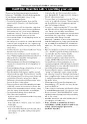
...power plug from the TV set , contact your unit Please read the following operating precautions before concluding that specified on both sides of this YAMAHA subwoofer system. For example, if 20 Hz-50 Hz sine waves from a test disc, bass sounds from the rear panel. Extremely loud .... To prevent fire or electrical shock, do not position with chemical solvents as that the unit is faulty. • Install this unit near the YST port of a disc, reduce the volume level to read the "TROUBLESHOOTING" section regarding common operating errors before use force on a TV. A vessel...
...power plug from the TV set , contact your unit Please read the following operating precautions before concluding that specified on both sides of this YAMAHA subwoofer system. For example, if 20 Hz-50 Hz sine waves from a test disc, bass sounds from the rear panel. Extremely loud .... To prevent fire or electrical shock, do not position with chemical solvents as that the unit is faulty. • Install this unit near the YST port of a disc, reduce the volume level to read the "TROUBLESHOOTING" section regarding common operating errors before use force on a TV. A vessel...
Owner's Manual
Page 5
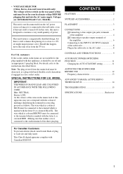
... marked with Canadian ICES-003. 1 CONTROLS AND THEIR FUNCTIONS 9 AUTOMATIC POWER-SWITCHING FUNCTION 11 Changing the AUTO STANDBY setting 11 ADJUSTING THE SUBWOOFER BEFORE USE 12 Frequency characteristics 13 ADVANCED YAMAHA ACTIVE SERVO TECHNOLOGY II 14 TROUBLESHOOTING 15 SPECIFICATIONS Backcover For Canadian Customers To prevent electric shock, match wide blade of the...
... marked with Canadian ICES-003. 1 CONTROLS AND THEIR FUNCTIONS 9 AUTOMATIC POWER-SWITCHING FUNCTION 11 Changing the AUTO STANDBY setting 11 ADJUSTING THE SUBWOOFER BEFORE USE 12 Frequency characteristics 13 ADVANCED YAMAHA ACTIVE SERVO TECHNOLOGY II 14 TROUBLESHOOTING 15 SPECIFICATIONS Backcover For Canadian Customers To prevent electric shock, match wide blade of the...
Owner's Manual
Page 6
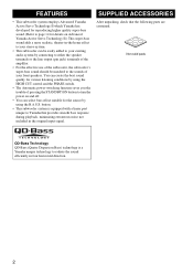
... with a linear port unique to radiate the sound efficiently in four horizontal direction. 2 FEATURES • This subwoofer system employs Advanced Yamaha Active Servo Technology II which Yamaha has developed for reproducing higher quality super-bass sound. (Refer to page 14 for details on Advanced...8226; You can create the best sound quality for the source by using the B.A.S.S. button. • This subwoofer system is a Yamaha unique technology to Yamaha that the following parts are contained. You can select bass effect suitable for various listening conditions by using the ...
... with a linear port unique to radiate the sound efficiently in four horizontal direction. 2 FEATURES • This subwoofer system employs Advanced Yamaha Active Servo Technology II which Yamaha has developed for reproducing higher quality super-bass sound. (Refer to page 14 for details on Advanced...8226; You can create the best sound quality for the source by using the B.A.S.S. button. • This subwoofer system is a Yamaha unique technology to Yamaha that the following parts are contained. You can select bass effect suitable for various listening conditions by using the ...
Owner's Manual
Page 7
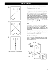
...non-skid pads C Put the provided non-skid pads at an angle as in fig. C is also possible, however, if the subwoofer system is recommended to prevent the subwoofer from the subwoofer when listening in the center of either the right or the left front speaker. (See fig. A or B . In such a... superbass sounds from moving by placing bookshelves etc. This is recommended to place it is recommended to place them on the outside of two subwoofers is placed directly facing the wall, the bass effect may be necessary to the wall. To prevent this from it is because "standing ...
...non-skid pads C Put the provided non-skid pads at an angle as in fig. C is also possible, however, if the subwoofer system is recommended to prevent the subwoofer from the subwoofer when listening in the center of either the right or the left front speaker. (See fig. A or B . In such a... superbass sounds from moving by placing bookshelves etc. This is recommended to place it is recommended to place them on the outside of two subwoofers is placed directly facing the wall, the bass effect may be necessary to the wall. To prevent this from it is because "standing ...
Owner's Manual
Page 8
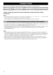
...they will not produce sound. 4 Also, refer to the owner's manual of your amplifier has no line output (pin jack) terminal Caution: Unplug the subwoofer and other audio/video components. 1 Connecting to line output (pin jack) terminals of the amplifier • To connect with an amplifier (or AV ... on the rear panel of the following two connecting methods that the amplifier has at least two sets of the SPLIT SUBWOOFER terminals. When you connect the subwoofer to the "R" side of PRE OUT terminals. Notes • All connections must be sure to connect the L /MONO INPUT2 terminal to...
...they will not produce sound. 4 Also, refer to the owner's manual of your amplifier has no line output (pin jack) terminal Caution: Unplug the subwoofer and other audio/video components. 1 Connecting to line output (pin jack) terminals of the amplifier • To connect with an amplifier (or AV ... on the rear panel of the following two connecting methods that the amplifier has at least two sets of the SPLIT SUBWOOFER terminals. When you connect the subwoofer to the "R" side of PRE OUT terminals. Notes • All connections must be sure to connect the L /MONO INPUT2 terminal to...
Owner's Manual
Page 9
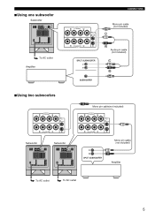
■Using one subwoofer Subwoofer To AC outlet Amplifier ■Using two subwoofers CONNECTIONS Mono pin cable (not included) Audio pin cable (not included) Mono pin cable(not included) Subwoofer Subwoofer To AC outlet To AC outlet Mono pin cable (not included) Amplifier 5
■Using one subwoofer Subwoofer To AC outlet Amplifier ■Using two subwoofers CONNECTIONS Mono pin cable (not included) Audio pin cable (not included) Mono pin cable(not included) Subwoofer Subwoofer To AC outlet To AC outlet Mono pin cable (not included) Amplifier 5
Owner's Manual
Page 10
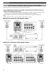
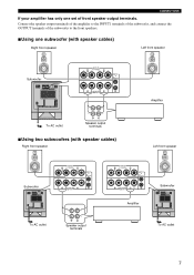
... of front speaker output terminals, see page 7. ■Using one set of front speaker output terminals of the amplifier to the INPUT1 terminals of the subwoofer, and connect the other set of front speaker output terminals of the amplifier to speaker output terminals of front speaker output terminals output sound signals...
... of front speaker output terminals, see page 7. ■Using one set of front speaker output terminals of the amplifier to the INPUT1 terminals of the subwoofer, and connect the other set of front speaker output terminals of the amplifier to speaker output terminals of front speaker output terminals output sound signals...
Owner's Manual
Page 11
CONNECTIONS If your amplifier has only one set of the subwoofer to the INPUT1 terminals of the subwoofer, and connect the OUTPUT terminals of front speaker output terminals. Connect the speaker output terminals of the amplifier to the front speakers. ■Using one subwoofer (with speaker cables) Right front speaker Left front speaker Subwoofer To AC outlet Speaker output terminals ■Using two subwoofers (with speaker cables) Right front speaker Amplifier Left front speaker Subwoofer To AC outlet Speaker output terminals Amplifier Subwoofer To AC outlet 7
CONNECTIONS If your amplifier has only one set of the subwoofer to the INPUT1 terminals of the subwoofer, and connect the OUTPUT terminals of front speaker output terminals. Connect the speaker output terminals of the amplifier to the front speakers. ■Using one subwoofer (with speaker cables) Right front speaker Left front speaker Subwoofer To AC outlet Speaker output terminals ■Using two subwoofers (with speaker cables) Right front speaker Amplifier Left front speaker Subwoofer To AC outlet Speaker output terminals Amplifier Subwoofer To AC outlet 7
Owner's Manual
Page 12
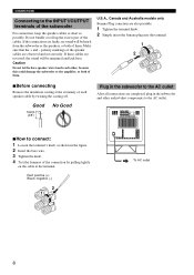
...outlet 8 Do not bundle or roll up the excess part of them . If the connections are faulty, no sound will be heard from the subwoofer or the speakers, or both of the cables. polarity markings of the speaker cables are also possible. 1 Tighten the terminal knob. 2 Simply ... the terminal's knob, as possible. CONNECTIONS Connecting to the INPUT1/OUTPUT terminals of the subwoofer For connection, keep the speaker cables as short as shown in the subwoofer and other , because this could damage the subwoofer or the amplifier, or both of them . Good 10mm (3/8") No Good Plug in the...
...outlet 8 Do not bundle or roll up the excess part of them . If the connections are faulty, no sound will be heard from the subwoofer or the speakers, or both of the cables. polarity markings of the speaker cables are also possible. 1 Tighten the terminal knob. 2 Simply ... the terminal's knob, as possible. CONNECTIONS Connecting to the INPUT1/OUTPUT terminals of the subwoofer For connection, keep the speaker cables as short as shown in the subwoofer and other , because this could damage the subwoofer or the amplifier, or both of them . Good 10mm (3/8") No Good Plug in the...
Owner's Manual
Page 13
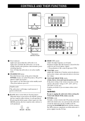
... video software is set the switch to the proper voltage (110V, 120V, 220V or 230-240V) of your dealer if you can turn on the subwoofer or turn on . In this button is pressed in to the MUSIC position, the bass sound in red while the... Rear panel (General model) 1 Power indicator Lights up in the standby mode. 2 STANDBY/ON button Press this switch to the ON position to use the subwoofer. Set this control represents 10 Hz. 5 VOLUME control Adjusts the volume level. Lights up in green.) Press again to set the...
... video software is set the switch to the proper voltage (110V, 120V, 220V or 230-240V) of your dealer if you can turn on the subwoofer or turn on . In this button is pressed in to the MUSIC position, the bass sound in red while the... Rear panel (General model) 1 Power indicator Lights up in the standby mode. 2 STANDBY/ON button Press this switch to the ON position to use the subwoofer. Set this control represents 10 Hz. 5 VOLUME control Adjusts the volume level. Lights up in green.) Press again to set the...
Owner's Manual
Page 14
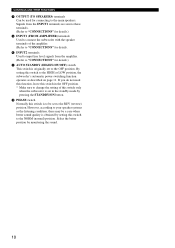
... (HIGH/LOW/OFF) switch This switch is originally set to the HIGH or LOW position, the subwoofer's automatic power-switching function operates as described on page 11. B PHASE switch Normally this switch only when the subwoofer is set to be a case when better sound quality is to the REV (reverse) position. ... speakers. Signals from the INPUT1 terminals are sent to these terminals. (Refer to "CONNECTIONS" for details.) 9 INPUT1 (FROM AMPLIFIER) terminals Used to connect the subwoofer with the speaker terminals of this switch is obtained by setting this switch to the OFF position.
... (HIGH/LOW/OFF) switch This switch is originally set to the HIGH or LOW position, the subwoofer's automatic power-switching function operates as described on page 11. B PHASE switch Normally this switch only when the subwoofer is set to be a case when better sound quality is to the REV (reverse) position. ... speakers. Signals from the INPUT1 terminals are sent to these terminals. (Refer to "CONNECTIONS" for details.) 9 INPUT1 (FROM AMPLIFIER) terminals Used to connect the subwoofer with the speaker terminals of this switch is obtained by setting this switch to the OFF position.
Owner's Manual
Page 15
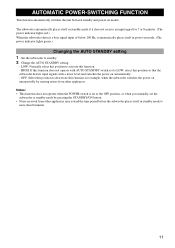
...and power-on unexpectedly by pressing the STANDBY/ON button. • Noise received from other appliances may extend the time period before the subwoofer places itself in standby mode to LOW, select this function. - HIGH: If this function does not operate with a lower level and... green.) Changing the AUTO STANDBY setting 1 Set the subwoofer to activate this position so that the subwoofer detects input signals with AUTO STANDBY switch set the subwoofer to standby mode by sensing noises from other appliances. The subwoofer automatically places itself in standby mode if it does not...
...and power-on unexpectedly by pressing the STANDBY/ON button. • Noise received from other appliances may extend the time period before the subwoofer places itself in standby mode to LOW, select this function. - HIGH: If this function does not operate with a lower level and... green.) Changing the AUTO STANDBY setting 1 Set the subwoofer to activate this position so that the subwoofer detects input signals with AUTO STANDBY switch set the subwoofer to standby mode by sensing noises from other appliances. The subwoofer automatically places itself in standby mode if it does not...
Owner's Manual
Page 16
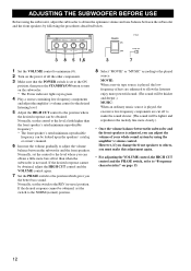
... adjustment again. • For adjusting the VOLUME control, the HIGH CUT control and the PHASE switch, refer to "Frequency characteristics" on the subwoofer. * The Power indicator lights up in green. 4 Play a source containing low-frequency components and adjust the amplifier's volume control to the ... the HIGH CUT control to the position where the desired response can obtain a little more clearly.) • Once the volume balance between the subwoofer and the front speakers is adjusted, you the better bass sound. Normally, set the switch to the NORM (normal) position. 8 Select "...
... adjustment again. • For adjusting the VOLUME control, the HIGH CUT control and the PHASE switch, refer to "Frequency characteristics" on the subwoofer. * The Power indicator lights up in green. 4 Play a source containing low-frequency components and adjust the amplifier's volume control to the ... the HIGH CUT control to the position where the desired response can obtain a little more clearly.) • Once the volume balance between the subwoofer and the front speakers is adjusted, you the better bass sound. Normally, set the switch to the NORM (normal) position. 8 Select "...
Owner's Manual
Page 17
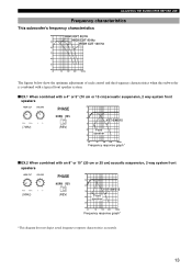
...control and the frequency characteristics when this subwoofer is combined with a typical front speaker system. ■ EX.1 When combined with a 4" or 5" (10 cm or 13 cm) acoustic suspension, 2 way system front speakers (70Hz) PHASE NORM REV (REV) dB 90 80 YST-SW515 70 60 Front speaker 50 40 ... or 10" (20 cm or 25 cm) acoustic suspension, 2 way system front speakers (50Hz) PHASE NORM REV (REV) dB 90 80 YST-SW515 70 60 Front speaker 50 40 20 50 100 200 500Hz Frequency response graph* *This diagram does not depict actual frequency response characteristics accurately. 13
...control and the frequency characteristics when this subwoofer is combined with a typical front speaker system. ■ EX.1 When combined with a 4" or 5" (10 cm or 13 cm) acoustic suspension, 2 way system front speakers (70Hz) PHASE NORM REV (REV) dB 90 80 YST-SW515 70 60 Front speaker 50 40 ... or 10" (20 cm or 25 cm) acoustic suspension, 2 way system front speakers (50Hz) PHASE NORM REV (REV) dB 90 80 YST-SW515 70 60 Front speaker 50 40 20 50 100 200 500Hz Frequency response graph* *This diagram does not depict actual frequency response characteristics accurately. 13
Owner's Manual
Page 19
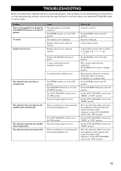
... Speaker cables are not connected securely. The subwoofer turns on automatically. Connect them securely. Set... the OFF position. Move the subwoofer farther away from such appliances and... of noise generated from external appliances etc. Reposition the subwoofer or break up . Set the AUTO STANDBY switch to... The subwoofer does not turn into the standby mode unexpectedly. The subwoofer turns into...to the OFF position. Move the subwoofer farther away from such appliances and/...to the "OFF" position. 15 The subwoofer does not turn on unexpectedly. along the ...
... Speaker cables are not connected securely. The subwoofer turns on automatically. Connect them securely. Set... the OFF position. Move the subwoofer farther away from such appliances and... of noise generated from external appliances etc. Reposition the subwoofer or break up . Set the AUTO STANDBY switch to... The subwoofer does not turn into the standby mode unexpectedly. The subwoofer turns into...to the OFF position. Move the subwoofer farther away from such appliances and/...to the "OFF" position. 15 The subwoofer does not turn on unexpectedly. along the ...


