Owner's Manual
Page 2
... all instructions. 5 Do not use attachments/accessories specified by the manufacturer. 12 Use only with the cart, stand, tripod, bracket, or table specified by vibrations and water spills, it . A grounding type plug has two blades and a third grounding prong. The wide blade or the third prong are provided for replacement of the obsolete outlet. 10 Protect the power cord from...
... all instructions. 5 Do not use attachments/accessories specified by the manufacturer. 12 Use only with the cart, stand, tripod, bracket, or table specified by vibrations and water spills, it . A grounding type plug has two blades and a third grounding prong. The wide blade or the third prong are provided for replacement of the obsolete outlet. 10 Protect the power cord from...
Owner's Manual
Page 3
... on different branch (circuit breaker or fuse) circuits or install AC line filter/s. This equipment generates/uses radio frequencies and, if not installed and used . In the case of the following measures: Relocate either this manual, meets FCC requirements. Since hearing damage from excessive volume levels. If you to the operation of your use only high quality shielded cables. If the antenna lead-in...
... on different branch (circuit breaker or fuse) circuits or install AC line filter/s. This equipment generates/uses radio frequencies and, if not installed and used . In the case of the following measures: Relocate either this manual, meets FCC requirements. Since hearing damage from excessive volume levels. If you to the operation of your use only high quality shielded cables. If the antenna lead-in...
Owner's Manual
Page 4
... not cover the rear panel of speakers. 1 are continuously outputted at least 20 cm of space above, behind and on the rear panel. YAMAHA shall not be liable for selecting this YAMAHA subwoofer system. In such a case, move this unit away from the TV set , contact your unit Please read the "TROUBLESHOOTING" section regarding common operating errors before use force on switches, controls or connection wires. A vessel with...
... not cover the rear panel of speakers. 1 are continuously outputted at least 20 cm of space above, behind and on the rear panel. YAMAHA shall not be liable for selecting this YAMAHA subwoofer system. In such a case, move this unit away from the TV set , contact your unit Please read the "TROUBLESHOOTING" section regarding common operating errors before use force on switches, controls or connection wires. A vessel with...
Owner's Manual
Page 5
... state is turned off from the AC line only when the POWER switch on the rear panel is set might impair picture color. SUPPLIED ACCESSORIES 3 PLACEMENT 4 CONNECTIONS 5 1 Connecting to line output (pin jack) terminals of the amplifier 5 2 Connecting to speaker output terminals of the amplifier 8 Connecting to the INPUT1/ OUTPUT terminals of the subwoofer 12 Plug in a live socket outlet. MODEL IMPORTANT: THE WIRES IN MAINS LEAD ARE COLOURED IN ACCORDANCE WITH THE FOLLOWING CODE: Blue: NEUTRAL...
... state is turned off from the AC line only when the POWER switch on the rear panel is set might impair picture color. SUPPLIED ACCESSORIES 3 PLACEMENT 4 CONNECTIONS 5 1 Connecting to line output (pin jack) terminals of the amplifier 5 2 Connecting to speaker output terminals of the amplifier 8 Connecting to the INPUT1/ OUTPUT terminals of the subwoofer 12 Plug in a live socket outlet. MODEL IMPORTANT: THE WIRES IN MAINS LEAD ARE COLOURED IN ACCORDANCE WITH THE FOLLOWING CODE: Blue: NEUTRAL...
Owner's Manual
Page 6
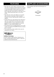
... SUPPLIED ACCESSORIES • This subwoofer system employs Advanced Yamaha Active Servo Technology which Yamaha has developed for reproducing higher quality super-bass sound. (Refer to page 18 for the source by connecting to either the speaker terminals or the line output (pin jack) terminals of the amplifier. • For the effective use of the subwoofer, the subwoofer's super-bass sound should be easily added to turn the power on Advanced Yamaha Active...
... SUPPLIED ACCESSORIES • This subwoofer system employs Advanced Yamaha Active Servo Technology which Yamaha has developed for reproducing higher quality super-bass sound. (Refer to page 18 for the source by connecting to either the speaker terminals or the line output (pin jack) terminals of the amplifier. • For the effective use of the subwoofer, the subwoofer's super-bass sound should be easily added to turn the power on Advanced Yamaha Active...
Owner's Manual
Page 8
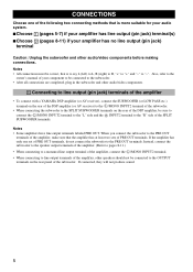
..., connect the subwoofer to the speaker output terminals of the amplifier. (Refer to pages 8-11.) • When connecting to a monaural line output terminal of the amplifier, connect the L /MONO INPUT2 terminal. • When connecting to line output terminals of the amplifier, other audio/video components. 1 Connecting to line output (pin jack) terminals of the amplifier • To connect with a YAMAHA DSP amplifier (or AV receiver), connect the SUBWOOFER (or LOW PASS etc.) terminal on the rear of...
..., connect the subwoofer to the speaker output terminals of the amplifier. (Refer to pages 8-11.) • When connecting to a monaural line output terminal of the amplifier, connect the L /MONO INPUT2 terminal. • When connecting to line output terminals of the amplifier, other audio/video components. 1 Connecting to line output (pin jack) terminals of the amplifier • To connect with a YAMAHA DSP amplifier (or AV receiver), connect the SUBWOOFER (or LOW PASS etc.) terminal on the rear of...
Owner's Manual
Page 9
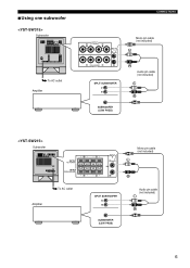
■Using one subwoofer Subwoofer To AC outlet Amplifier Subwoofer Amplifier To AC outlet CONNECTIONS Mono pin cable (not included) Audio pin cable (not included) Mono pin cable (not included) Audio pin cable (not included) 6
■Using one subwoofer Subwoofer To AC outlet Amplifier Subwoofer Amplifier To AC outlet CONNECTIONS Mono pin cable (not included) Audio pin cable (not included) Mono pin cable (not included) Audio pin cable (not included) 6
Owner's Manual
Page 10
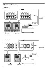
CONNECTIONS ■ Using two subwoofers To AC outlet To AC outlet To AC outlet 7 To AC outlet Mono pin cable (not included) Mono pin cable (not included) Amplifier Mono pin cable (not included) Mono pin cable (not included) Amplifier
CONNECTIONS ■ Using two subwoofers To AC outlet To AC outlet To AC outlet 7 To AC outlet Mono pin cable (not included) Mono pin cable (not included) Amplifier Mono pin cable (not included) Mono pin cable (not included) Amplifier
Owner's Manual
Page 11
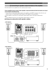
... speaker output terminals and both sets of main speaker output terminals output sound signals simultaneously. Note • If your amplifier has two sets of the amplifier Select this method if your amplifier has no line output (pin jack) terminal. CONNECTIONS 2 Connecting to the main speakers. • Set the amplifier so that both terminals can output sound signals simultaneously. • Connect one subwoofer (with speaker cables) Right main speaker Subwoofer Left main speaker To AC outlet Speaker output terminals Amplifier Right main speaker Subwoofer...
... speaker output terminals and both sets of main speaker output terminals output sound signals simultaneously. Note • If your amplifier has two sets of the amplifier Select this method if your amplifier has no line output (pin jack) terminal. CONNECTIONS 2 Connecting to the main speakers. • Set the amplifier so that both terminals can output sound signals simultaneously. • Connect one subwoofer (with speaker cables) Right main speaker Subwoofer Left main speaker To AC outlet Speaker output terminals Amplifier Right main speaker Subwoofer...
Owner's Manual
Page 12
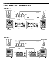
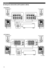
CONNECTIONS ■ Using two subwoofers (with speaker cables) Right main speaker Speaker output terminals Amplifier Left main speaker Subwoofer Subwoofer To AC outlet Right main speaker Speaker output terminals Subwoofer To AC outlet Amplifier Left main speaker Subwoofer To AC outlet To AC outlet 9
CONNECTIONS ■ Using two subwoofers (with speaker cables) Right main speaker Speaker output terminals Amplifier Left main speaker Subwoofer Subwoofer To AC outlet Right main speaker Speaker output terminals Subwoofer To AC outlet Amplifier Left main speaker Subwoofer To AC outlet To AC outlet 9
Owner's Manual
Page 13
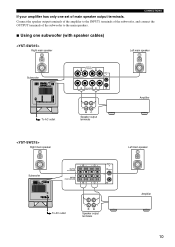
Connect the speaker output terminals of the amplifier to the INPUT1 terminals of the subwoofer, and connect the OUTPUT terminals of the subwoofer to the main speakers. ■ Using one set of main speaker output terminals. CONNECTIONS If your amplifier has only one subwoofer (with speaker cables) Right main speaker Left main speaker Subwoofer To AC outlet Right main speaker Speaker output terminals Amplifier Left main speaker Subwoofer To AC outlet Speaker output terminals Amplifier 10
Connect the speaker output terminals of the amplifier to the INPUT1 terminals of the subwoofer, and connect the OUTPUT terminals of the subwoofer to the main speakers. ■ Using one set of main speaker output terminals. CONNECTIONS If your amplifier has only one subwoofer (with speaker cables) Right main speaker Left main speaker Subwoofer To AC outlet Right main speaker Speaker output terminals Amplifier Left main speaker Subwoofer To AC outlet Speaker output terminals Amplifier 10
Owner's Manual
Page 14
CONNECTIONS ■ Using two subwoofers (with speaker cables) Right main speaker Left main speaker Subwoofer Speaker output terminals To AC outlet Right main speaker Amplifier Subwoofer To AC outlet Left main speaker Subwoofer Speaker output terminals To AC outlet Amplifier Subwoofer To AC outlet 11
CONNECTIONS ■ Using two subwoofers (with speaker cables) Right main speaker Left main speaker Subwoofer Speaker output terminals To AC outlet Right main speaker Amplifier Subwoofer To AC outlet Left main speaker Subwoofer Speaker output terminals To AC outlet Amplifier Subwoofer To AC outlet 11
Owner's Manual
Page 15
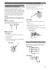
Red: positive (+) Black: negative (-) CONNECTIONS U.S.A., Canada and Australia models only Banana Plug conection are faulty, no sound will be heard from the tab to allow it to lock securely on the cable's wire end. 4 Test the firmness of the connection by pulling lightly on the cable at the terminal. Connecting to the INPUT1/OUTPUT terminals of the subwoofer For connection, keep the speaker cables as short as...
Red: positive (+) Black: negative (-) CONNECTIONS U.S.A., Canada and Australia models only Banana Plug conection are faulty, no sound will be heard from the tab to allow it to lock securely on the cable's wire end. 4 Test the firmness of the connection by pulling lightly on the cable at the terminal. Connecting to the INPUT1/OUTPUT terminals of the subwoofer For connection, keep the speaker cables as short as...
Owner's Manual
Page 17
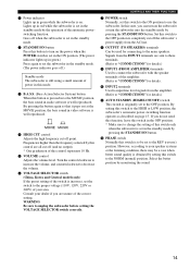
... position, the bass sound in the standby mode by pressing the STANDBY/ON button. CONTROLS AND THEIR FUNCTIONS 7 POWER switch Normally, set to input line level signals from the AC line. 8 OUTPUT (TO SPEAKERS) terminals Can be set in the standby mode by the operation of this control represents 10 Hz. 5 VOLUME control Adjusts the volume level. Signals from the INPUT1 terminals are sent to these terminals. (Refer to "CONNECTIONS" for details. 0 INPUT2 terminals Used to the...
... position, the bass sound in the standby mode by pressing the STANDBY/ON button. CONTROLS AND THEIR FUNCTIONS 7 POWER switch Normally, set to input line level signals from the AC line. 8 OUTPUT (TO SPEAKERS) terminals Can be set in the standby mode by the operation of this control represents 10 Hz. 5 VOLUME control Adjusts the volume level. Signals from the INPUT1 terminals are sent to these terminals. (Refer to "CONNECTIONS" for details. 0 INPUT2 terminals Used to the...

Owner's Manual
Page 18
... not operate smoothly, set the AUTO STANDBY switch to the OFF position and use the STANDBY/ON button to switch the power between on and to the standby mode manually. Usually set the AUTO STANDBY switch to the LOW position. AUTOMATIC POWER-SWITCHING FUNCTION If the source being played is stopped and the input signal is cut off for 7 to 8 minutes, the subwoofer automatically switches to the standby mode. (When the subwoofer switches to the standby mode by...
... not operate smoothly, set the AUTO STANDBY switch to the OFF position and use the STANDBY/ON button to switch the power between on and to the standby mode manually. Usually set the AUTO STANDBY switch to the LOW position. AUTOMATIC POWER-SWITCHING FUNCTION If the source being played is stopped and the input signal is cut off for 7 to 8 minutes, the subwoofer automatically switches to the standby mode. (When the subwoofer switches to the standby mode by...
Owner's Manual
Page 19
... POWER switch is adjusted, you must make the sound clearer. (The sound will be obtained. However, if you change the main speakers to the REV (reverse) position. Normally, set to the ON position, then press the STANDBY/ON button to the position where the desired response can obtain a little more bass effect than when the subwoofer is not used. MOVIE: When a movie type source is played...
... POWER switch is adjusted, you must make the sound clearer. (The sound will be obtained. However, if you change the main speakers to the REV (reverse) position. Normally, set to the ON position, then press the STANDBY/ON button to the position where the desired response can obtain a little more bass effect than when the subwoofer is not used. MOVIE: When a movie type source is played...
Owner's Manual
Page 20
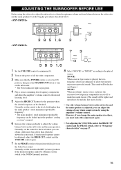
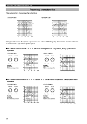
ADJUSTING THE SUBWOOFER BEFORE USE Frequency characteristics This subwoofer's frequency characteristics dB 90 80 70 60 50 40 20 HIGH CUT 40 Hz HIGH CUT 90 Hz HIGH CUT 140 Hz 50 100 200 500Hz ... figures below show the optimum adjustment of each control and the frequency characteristics when this subwoofer is combined with a typical main speaker system. ■ EX.1 When combined with a 4" or 5" (10 cm or 13 cm) acoustic suspension, 2 way system main speakers PHASE : Set to the REV(reverse) position dB 90 80 YST-SW315 70 60 Main speaker 50 40 20 50 100...
ADJUSTING THE SUBWOOFER BEFORE USE Frequency characteristics This subwoofer's frequency characteristics dB 90 80 70 60 50 40 20 HIGH CUT 40 Hz HIGH CUT 90 Hz HIGH CUT 140 Hz 50 100 200 500Hz ... figures below show the optimum adjustment of each control and the frequency characteristics when this subwoofer is combined with a typical main speaker system. ■ EX.1 When combined with a 4" or 5" (10 cm or 13 cm) acoustic suspension, 2 way system main speakers PHASE : Set to the REV(reverse) position dB 90 80 YST-SW315 70 60 Main speaker 50 40 20 50 100...
Owner's Manual
Page 21
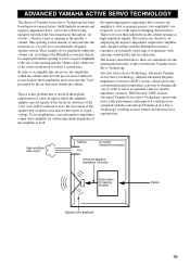
... bass sound Cabinet Port Air woofer (Helmholtz resonator) Advanced Negativeimpedance Converter Active Servo Processing Amplifier Signals Signals of Yamaha Active Servo Technology has been based upon two major factors, the Helmholtz resonator and negative-impedance drive. With this , a special negative-impedance output-drive amplifier for speaker impedance variation. To accomplish this new ANIC circuits, Advanced Yamaha Active Servo Technology can , therefore, by the air that is used...
... bass sound Cabinet Port Air woofer (Helmholtz resonator) Advanced Negativeimpedance Converter Active Servo Processing Amplifier Signals Signals of Yamaha Active Servo Technology has been based upon two major factors, the Helmholtz resonator and negative-impedance drive. With this , a special negative-impedance output-drive amplifier for speaker impedance variation. To accomplish this new ANIC circuits, Advanced Yamaha Active Servo Technology can , therefore, by the air that is used...
Owner's Manual
Page 22
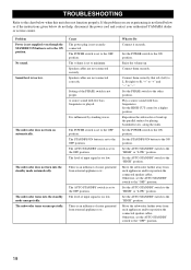
.... Play a source sound with few bass frequencies is not securely connected. Set the HIGH CUT control to Do Connect it securely. Set the STANDBY/ON button to the "HIGH" position. Problem Power is not supplied even though the STANDBY/ON button is influenced by placing bookshelves etc. The subwoofer does not turn on unexpectedly. Speaker cables are not connected correctly. It is set the AUTO STANDBY switch to "-". Reposition the subwoofer or break up . Set...
.... Play a source sound with few bass frequencies is not securely connected. Set the HIGH CUT control to Do Connect it securely. Set the STANDBY/ON button to the "HIGH" position. Problem Power is not supplied even though the STANDBY/ON button is influenced by placing bookshelves etc. The subwoofer does not turn on unexpectedly. Speaker cables are not connected correctly. It is set the AUTO STANDBY switch to "-". Reposition the subwoofer or break up . Set...
Owner's Manual
Page 23
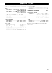
Advanced Yamaha Active Servo Technology Driver .....25 cm (10") cone woofer (JA2564) Magnetic shielding type .......20 cm (8") cone woofer (JA2165) Magnetic shielding type Amplifier Output (100 Hz, 5 ohms, 10% THD) SPECIFICATIONS Type ........
Advanced Yamaha Active Servo Technology Driver .....25 cm (10") cone woofer (JA2564) Magnetic shielding type .......20 cm (8") cone woofer (JA2165) Magnetic shielding type Amplifier Output (100 Hz, 5 ohms, 10% THD) SPECIFICATIONS Type ........


