Owner's Manual
Page 4
...Use a clean, dry cloth. • Be sure to read the "TROUBLESHOOTING" section regarding common operating errors before use. YAMAHA shall not be liable for selecting this YAMAHA subwoofer system. Thank you for any damage and/or injury caused by allowing enough spaces around this unit or avoiding excess humidification....panel. It might fall. Extremely loud playing of this unit with a newspaper, a tablecloth, a curtain, etc. If something drops into the YST port located on a TV. falls by super-bass frequencies may cause damage to this unit. • Never place a fragile object near the...
...Use a clean, dry cloth. • Be sure to read the "TROUBLESHOOTING" section regarding common operating errors before use. YAMAHA shall not be liable for selecting this YAMAHA subwoofer system. Thank you for any damage and/or injury caused by allowing enough spaces around this unit or avoiding excess humidification....panel. It might fall. Extremely loud playing of this unit with a newspaper, a tablecloth, a curtain, etc. If something drops into the YST port located on a TV. falls by super-bass frequencies may cause damage to this unit. • Never place a fragile object near the...
Owner's Manual
Page 5
...details, refer to the AC outlet 12 CONTROLS AND THEIR FUNCTIONS 13 AUTOMATIC POWER-SWITCHING FUNCTION 15 ADJUSTING THE SUBWOOFER BEFORE USE 16 Frequency characteristics 17 ADVANCED YAMAHA ACTIVE SERVO TECHNOLOGY 18 TROUBLESHOOTING 19 SPECIAL INSTRUCTIONS FOR U.K. Note: The plug severed from the mains lead ...correspond with the coloured markings identifying the terminals in the mains lead of power. customers If the socket outlets in the subwoofer to the instructions described below. This unit features a magnetically shielded design, but there is still a chance that neither core...
...details, refer to the AC outlet 12 CONTROLS AND THEIR FUNCTIONS 13 AUTOMATIC POWER-SWITCHING FUNCTION 15 ADJUSTING THE SUBWOOFER BEFORE USE 16 Frequency characteristics 17 ADVANCED YAMAHA ACTIVE SERVO TECHNOLOGY 18 TROUBLESHOOTING 19 SPECIAL INSTRUCTIONS FOR U.K. Note: The plug severed from the mains lead ...correspond with the coloured markings identifying the terminals in the mains lead of power. customers If the socket outlets in the subwoofer to the instructions described below. This unit features a magnetically shielded design, but there is still a chance that neither core...
Owner's Manual
Page 6
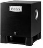
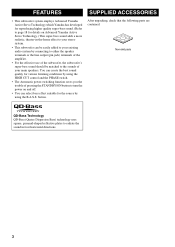
...) terminals of the amplifier. • For the effective use of pressing the STANDBY/ON button to turn the power on Advanced Yamaha Active Servo Technology.) This super-bass sound adds a more realistic, theater-in four horizontal directions. 3 After unpacking, check that ...the following parts are contained. FEATURES SUPPLIED ACCESSORIES • This subwoofer system employs Advanced Yamaha Active Servo Technology which Yamaha has developed for reproducing higher quality super-bass sound. (Refer to page 18 for details on and off. &#...
...) terminals of the amplifier. • For the effective use of pressing the STANDBY/ON button to turn the power on Advanced Yamaha Active Servo Technology.) This super-bass sound adds a more realistic, theater-in four horizontal directions. 3 After unpacking, check that ...the following parts are contained. FEATURES SUPPLIED ACCESSORIES • This subwoofer system employs Advanced Yamaha Active Servo Technology which Yamaha has developed for reproducing higher quality super-bass sound. (Refer to page 18 for details on and off. &#...
Owner's Manual
Page 7
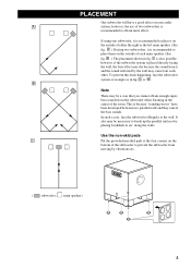
... two parallel walls and they cancel the bass sounds. along the walls. A or B . A .) If using one subwoofer, it is recommended to place it on the bottom of the subwoofer to prevent the subwoofer from it is recommended to place them on your audio A system, however, the use of the room. B .) The...a good effect on the outside of each other. It also may be a case that you cannot obtain enough superbass sounds from happening, face the subwoofer system at the four corners on the outside of either the right or the left main speaker. (See fig. Use the non-skid pads C Put...
... two parallel walls and they cancel the bass sounds. along the walls. A or B . A .) If using one subwoofer, it is recommended to place it on the bottom of the subwoofer to prevent the subwoofer from it is recommended to place them on your audio A system, however, the use of the room. B .) The...a good effect on the outside of each other. It also may be a case that you cannot obtain enough superbass sounds from happening, face the subwoofer system at the four corners on the outside of either the right or the left main speaker. (See fig. Use the non-skid pads C Put...
Owner's Manual
Page 8
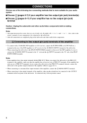
...no line output (pin jack) terminal Caution: Unplug the subwoofer and other audio/video components. 1 Connecting to line output (pin jack) terminals of the amplifier • To connect with a YAMAHA DSP amplifier (or AV receiver), connect the SUBWOOFER (or LOW PASS etc.) terminal on the rear of the... DSP amplifier (or AV receiver) to the L /MONO INPUT2 terminal of the subwoofer. • When connecting the subwoofer to the SPLIT SUBWOOFER terminals on the rear panel...
...no line output (pin jack) terminal Caution: Unplug the subwoofer and other audio/video components. 1 Connecting to line output (pin jack) terminals of the amplifier • To connect with a YAMAHA DSP amplifier (or AV receiver), connect the SUBWOOFER (or LOW PASS etc.) terminal on the rear of the... DSP amplifier (or AV receiver) to the L /MONO INPUT2 terminal of the subwoofer. • When connecting the subwoofer to the SPLIT SUBWOOFER terminals on the rear panel...
Owner's Manual
Page 9
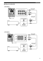
■Using one subwoofer Subwoofer To AC outlet Amplifier Subwoofer Amplifier To AC outlet CONNECTIONS Mono pin cable (not included) Audio pin cable (not included) Mono pin cable (not included) Audio pin cable (not included) 6
■Using one subwoofer Subwoofer To AC outlet Amplifier Subwoofer Amplifier To AC outlet CONNECTIONS Mono pin cable (not included) Audio pin cable (not included) Mono pin cable (not included) Audio pin cable (not included) 6
Owner's Manual
Page 10
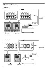
CONNECTIONS ■ Using two subwoofers To AC outlet To AC outlet To AC outlet 7 To AC outlet Mono pin cable (not included) Mono pin cable (not included) Amplifier Mono pin cable (not included) Mono pin cable (not included) Amplifier
CONNECTIONS ■ Using two subwoofers To AC outlet To AC outlet To AC outlet 7 To AC outlet Mono pin cable (not included) Mono pin cable (not included) Amplifier Mono pin cable (not included) Mono pin cable (not included) Amplifier
Owner's Manual
Page 11
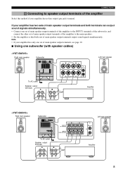
... terminals, see page 10. ■ Using one set of main speaker output terminals of the amplifier to the INPUT1 terminals of the subwoofer, and connect the other set of main speaker output terminals of the amplifier to speaker output terminals of the amplifier Select this method if.... CONNECTIONS 2 Connecting to the main speakers. • Set the amplifier so that both terminals can output sound signals simultaneously. • Connect one subwoofer (with speaker cables) Right main speaker Subwoofer Left main speaker To AC outlet Speaker output terminals Amplifier Right main speaker...
... terminals, see page 10. ■ Using one set of main speaker output terminals of the amplifier to the INPUT1 terminals of the subwoofer, and connect the other set of main speaker output terminals of the amplifier to speaker output terminals of the amplifier Select this method if.... CONNECTIONS 2 Connecting to the main speakers. • Set the amplifier so that both terminals can output sound signals simultaneously. • Connect one subwoofer (with speaker cables) Right main speaker Subwoofer Left main speaker To AC outlet Speaker output terminals Amplifier Right main speaker...
Owner's Manual
Page 12
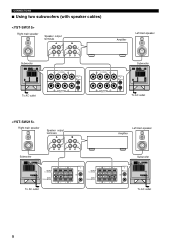
CONNECTIONS ■ Using two subwoofers (with speaker cables) Right main speaker Speaker output terminals Amplifier Left main speaker Subwoofer Subwoofer To AC outlet Right main speaker Speaker output terminals Subwoofer To AC outlet Amplifier Left main speaker Subwoofer To AC outlet To AC outlet 9
CONNECTIONS ■ Using two subwoofers (with speaker cables) Right main speaker Speaker output terminals Amplifier Left main speaker Subwoofer Subwoofer To AC outlet Right main speaker Speaker output terminals Subwoofer To AC outlet Amplifier Left main speaker Subwoofer To AC outlet To AC outlet 9
Owner's Manual
Page 13
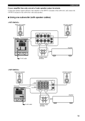
Connect the speaker output terminals of the amplifier to the INPUT1 terminals of the subwoofer, and connect the OUTPUT terminals of the subwoofer to the main speakers. ■ Using one set of main speaker output terminals. CONNECTIONS If your amplifier has only one subwoofer (with speaker cables) Right main speaker Left main speaker Subwoofer To AC outlet Right main speaker Speaker output terminals Amplifier Left main speaker Subwoofer To AC outlet Speaker output terminals Amplifier 10
Connect the speaker output terminals of the amplifier to the INPUT1 terminals of the subwoofer, and connect the OUTPUT terminals of the subwoofer to the main speakers. ■ Using one set of main speaker output terminals. CONNECTIONS If your amplifier has only one subwoofer (with speaker cables) Right main speaker Left main speaker Subwoofer To AC outlet Right main speaker Speaker output terminals Amplifier Left main speaker Subwoofer To AC outlet Speaker output terminals Amplifier 10
Owner's Manual
Page 14
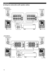
CONNECTIONS ■ Using two subwoofers (with speaker cables) Right main speaker Left main speaker Subwoofer Speaker output terminals To AC outlet Right main speaker Amplifier Subwoofer To AC outlet Left main speaker Subwoofer Speaker output terminals To AC outlet Amplifier Subwoofer To AC outlet 11
CONNECTIONS ■ Using two subwoofers (with speaker cables) Right main speaker Left main speaker Subwoofer Speaker output terminals To AC outlet Right main speaker Amplifier Subwoofer To AC outlet Left main speaker Subwoofer Speaker output terminals To AC outlet Amplifier Subwoofer To AC outlet 11
Owner's Manual
Page 15
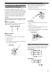
... insert the banana plug into the terminal. 1 Press and hold the terminal's tab, as possible. Red: positive (+) Black: negative (-) Plug in the subwoofer to the AC outlet After all connections are faulty, no sound will be heard from the tab to allow it to lock securely on the... speakers, or both of them . Connecting to the INPUT1/OUTPUT terminals of the subwoofer For connection, keep the speaker cables as short as shown in the subwoofer and other , because this could damage the subwoofer or the amplifier, or both of them . ■Before connecting Remove the insulation...
... insert the banana plug into the terminal. 1 Press and hold the terminal's tab, as possible. Red: positive (+) Black: negative (-) Plug in the subwoofer to the AC outlet After all connections are faulty, no sound will be heard from the tab to allow it to lock securely on the... speakers, or both of them . Connecting to the INPUT1/OUTPUT terminals of the subwoofer For connection, keep the speaker cables as short as shown in the subwoofer and other , because this could damage the subwoofer or the amplifier, or both of them . ■Before connecting Remove the insulation...
Owner's Manual
Page 17
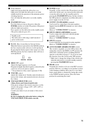
..." for details.) A AUTO STANDBY (HIGH/LOW/OFF) switch This switch is to be used for details. 0 INPUT2 terminals Used to unplug the subwoofer before setting the VOLTAGE SELECTOR switch correctly. B PHASE switch Normally this switch is originally set this switch to decrease the volume. 6 VOLTAGE SELECTOR switch... your speaker systems or the listening condition, there may be a case when better sound quality is incorrect, set in red while the subwoofer is well reproduced. 4 HIGH CUT control Adjusts the high frequency cut off point. However, according to your dealer if you do not...
..." for details.) A AUTO STANDBY (HIGH/LOW/OFF) switch This switch is to be used for details. 0 INPUT2 terminals Used to unplug the subwoofer before setting the VOLTAGE SELECTOR switch correctly. B PHASE switch Normally this switch is originally set this switch to decrease the volume. 6 VOLTAGE SELECTOR switch... your speaker systems or the listening condition, there may be a case when better sound quality is incorrect, set in red while the subwoofer is well reproduced. 4 HIGH CUT control Adjusts the high frequency cut off point. However, according to your dealer if you do not...
Owner's Manual
Page 18
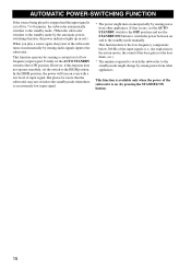
... POWER-SWITCHING FUNCTION If the source being played is stopped and the input signal is cut off for 7 to 8 minutes, the subwoofer automatically switches to the standby mode. (When the subwoofer switches to the standby mode by the automatic powerswitching function, the power indicator lights up in the action movie, the sound... explosion in red.) When you play a source again, the power of the bass guitar or the bass drum, etc.). * The minutes required to switch the subwoofer to the standby mode might turn on unexpectedly by sensing audio signals input to the HIGH position. If that the...
... POWER-SWITCHING FUNCTION If the source being played is stopped and the input signal is cut off for 7 to 8 minutes, the subwoofer automatically switches to the standby mode. (When the subwoofer switches to the standby mode by the automatic powerswitching function, the power indicator lights up in the action movie, the sound... explosion in red.) When you play a source again, the power of the bass guitar or the bass drum, etc.). * The minutes required to switch the subwoofer to the standby mode might turn on unexpectedly by sensing audio signals input to the HIGH position. If that the...
Owner's Manual
Page 19
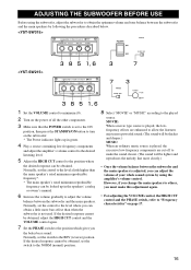
... this adjustment again. • For adjusting the VOLUME control, the HIGH CUT control and the PHASE switch, refer to "Frequency characteristics" on the subwoofer. * The Power indicator lights up in green. 4 Play a source containing low-frequency components and adjust the amplifier's volume control to the desired ...CUT control to the position where the desired response can be lighter and reproduces the melody line more bass effect than when the subwoofer is played, the excessive low-frequency components are enhanced to allow the listeners enjoy more powerful sound. (The sound will be ...
... this adjustment again. • For adjusting the VOLUME control, the HIGH CUT control and the PHASE switch, refer to "Frequency characteristics" on the subwoofer. * The Power indicator lights up in green. 4 Play a source containing low-frequency components and adjust the amplifier's volume control to the desired ...CUT control to the position where the desired response can be lighter and reproduces the melody line more bass effect than when the subwoofer is played, the excessive low-frequency components are enhanced to allow the listeners enjoy more powerful sound. (The sound will be ...
Owner's Manual
Page 20
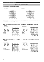
... each control and the frequency characteristics when this subwoofer is combined with a typical main speaker system. ■ EX.1 When combined with a 4" or 5" (10 cm or 13 cm) acoustic suspension, 2 way system main speakers PHASE : Set to the REV(reverse) position dB 90 80 YST-SW315 70 60 Main speaker 50 40 20 50... with an 8" or 10" (20 cm or 25 cm) acoustic suspension, 2 way system main speakers PHASE : Set to the REV(reverse) position dB 90 80 YST-SW315 70 60 Main speaker 50 40 20 50 100 200 500Hz PHASE : Set to the REV(reverse) position dB 90 80...
... each control and the frequency characteristics when this subwoofer is combined with a typical main speaker system. ■ EX.1 When combined with a 4" or 5" (10 cm or 13 cm) acoustic suspension, 2 way system main speakers PHASE : Set to the REV(reverse) position dB 90 80 YST-SW315 70 60 Main speaker 50 40 20 50... with an 8" or 10" (20 cm or 25 cm) acoustic suspension, 2 way system main speakers PHASE : Set to the REV(reverse) position dB 90 80 YST-SW315 70 60 Main speaker 50 40 20 50 100 200 500Hz PHASE : Set to the REV(reverse) position dB 90 80...
Owner's Manual
Page 22
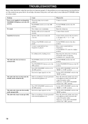
...POWER switch to the chart below do not help, disconnect the power cord and contact your authorized YAMAHA dealer or service center. Connect them securely. Set the AUTO STANDBY switch to the ON position. The subwoofer turns into the standby mode automatically. The POWER switch is L (left) to L, R ... position. Raise the volume up the parallel surface by standing waves. Set the POWER switch to the "HIGH" position. Move the subwoofer farther away from such appliances and/or reposition the connected speaker cables. Otherwise, set to "-". Set the STANDBY/ON button to the...
...POWER switch to the chart below do not help, disconnect the power cord and contact your authorized YAMAHA dealer or service center. Connect them securely. Set the AUTO STANDBY switch to the ON position. The subwoofer turns into the standby mode automatically. The POWER switch is L (left) to L, R ... position. Raise the volume up the parallel surface by standing waves. Set the POWER switch to the "HIGH" position. Move the subwoofer farther away from such appliances and/or reposition the connected speaker cables. Otherwise, set to "-". Set the STANDBY/ON button to the...


