Owner's Manual
Page 5
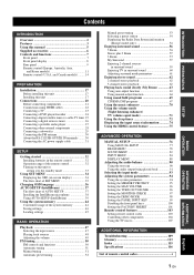
...tuning 53 Selecting a preset station 54 Displaying the Radio Data System information (Europe model only 54 Enjoying surround sound 56 5 Beam 56 Stereo plus 3 Beam 57 3 Beam 57 ...panel 7 Front panel display 8 Rear panel 9 Remote control (Europe, Australia, Asia, and Korea models 11 Remote control (U.S.A. and Canada models) ......... 14 PREPARATION Installation 17 Before installing this unit 17 Installing this unit 17 Connections 20 Before connecting components 21 Connections using HDMI cables 22 Connecting a TV 23 Connecting a DVD player/recorder 24 Connecting a digital...
...tuning 53 Selecting a preset station 54 Displaying the Radio Data System information (Europe model only 54 Enjoying surround sound 56 5 Beam 56 Stereo plus 3 Beam 57 3 Beam 57 ...panel 7 Front panel display 8 Rear panel 9 Remote control (Europe, Australia, Asia, and Korea models 11 Remote control (U.S.A. and Canada models) ......... 14 PREPARATION Installation 17 Before installing this unit 17 Installing this unit 17 Connections 20 Before connecting components 21 Connections using HDMI cables 22 Connecting a TV 23 Connecting a DVD player/recorder 24 Connecting a digital...
Owner's Manual
Page 11
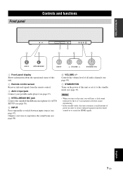
...3 AUX 3 INTELLIBEAM MIC 4 1 5 2 INPUT VOLUME + STANDBY/ON 6 7 AUX 3 INTELLIBEAM MIC INPUT VOLUME + STANDBY/ON 1 Front panel display Shows information about the operational status of this unit. 2 Remote control sensor Receives infrared signals from the remote control or to switch between input ...see page 49). 7 STANDBY/ON Turns on this unit, you will hear a click sound followed by the 4 to 5-second interval before sound reproducing. • In the standby mode, this unit or sets it to experience the sound beam (see page 98). 6 VOLUME +/- Outputs a test tone to the standby ...
...3 AUX 3 INTELLIBEAM MIC 4 1 5 2 INPUT VOLUME + STANDBY/ON 6 7 AUX 3 INTELLIBEAM MIC INPUT VOLUME + STANDBY/ON 1 Front panel display Shows information about the operational status of this unit. 2 Remote control sensor Receives infrared signals from the remote control or to switch between input ...see page 49). 7 STANDBY/ON Turns on this unit, you will hear a click sound followed by the 4 to 5-second interval before sound reproducing. • In the standby mode, this unit or sets it to experience the sound beam (see page 98). 6 VOLUME +/- Outputs a test tone to the standby ...
Owner's Manual
Page 12
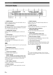
...available for the U.S.A. Note The neural decoder is set (see page 72). y You can adjust the brightness and display setting of the front panel display using the F.DISPLAY SET parameter in MANUAL SETUP (see page 88). 8 En D XM indicator (U.S.A. and Canada models only) Lights up...indicator Lights up when a sound field program is selected (see page 67). 4 PCM indicator Lights up when this unit is displayed (see page 58). C Radio Data System indicators (Europe model only) Show the current Radio Data System status. The channel component of the current digital input signal is reproducing PCM...
...available for the U.S.A. Note The neural decoder is set (see page 72). y You can adjust the brightness and display setting of the front panel display using the F.DISPLAY SET parameter in MANUAL SETUP (see page 88). 8 En D XM indicator (U.S.A. and Canada models only) Lights up...indicator Lights up when a sound field program is selected (see page 67). 4 PCM indicator Lights up when this unit is displayed (see page 58). C Radio Data System indicators (Europe model only) Show the current Radio Data System status. The channel component of the current digital input signal is reproducing PCM...
Owner's Manual
Page 13
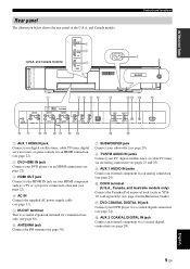
...only) Connect the Yamaha iPod universal dock (such as YDS10, sold separately) (see page 2 in the Reference Guide). B AUX 2 COAXIAL DIGITAL IN jack Connect an external component via a coaxial digital connection (see page 28). ANTENNA COMPONENT COMPONENT SUBWOOFER SYSTEM CONNECTOR VIDEO OUT ...digital satellite tuner, cable TV tuner, digital air wave tuner, or game console via an HDMI connection (see page 22). 2 DVD HDMI IN jack Connect your DVD player via an HDMI connection (see page 22). 3 HDMI OUT jack Connect to the HDMI IN jack on your HDMI component such as a TV or a projector...
...only) Connect the Yamaha iPod universal dock (such as YDS10, sold separately) (see page 2 in the Reference Guide). B AUX 2 COAXIAL DIGITAL IN jack Connect an external component via a coaxial digital connection (see page 28). ANTENNA COMPONENT COMPONENT SUBWOOFER SYSTEM CONNECTOR VIDEO OUT ...digital satellite tuner, cable TV tuner, digital air wave tuner, or game console via an HDMI connection (see page 22). 2 DVD HDMI IN jack Connect your DVD player via an HDMI connection (see page 22). 3 HDMI OUT jack Connect to the HDMI IN jack on your HDMI component such as a TV or a projector...
Owner's Manual
Page 25
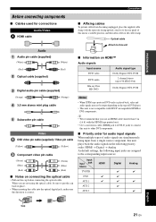
...HDCP-incompatible HDMI or DVI components. Optical cable Audio Audio pin cable (supplied) (White) (Red) Optical cable (supplied) (White) (Red) Digital audio pin cable (supplied) Attach to this unit plays back the audio signals in the cable clamp. PREPARATION Connections Before connecting components ■ ...than 5 m (16 ft) with the HDMI logo printed on it to the rear panel of this unit in a suitable position, and then affix cables in the following priority order: HDMI → Digital → Analog As default settings, the following input jacks are assigned to the corresponding ...
...HDCP-incompatible HDMI or DVI components. Optical cable Audio Audio pin cable (supplied) (White) (Red) Optical cable (supplied) (White) (Red) Digital audio pin cable (supplied) Attach to this unit plays back the audio signals in the cable clamp. PREPARATION Connections Before connecting components ■ ...than 5 m (16 ft) with the HDMI logo printed on it to the rear panel of this unit in a suitable position, and then affix cables in the following priority order: HDMI → Digital → Analog As default settings, the following input jacks are assigned to the corresponding ...
Owner's Manual
Page 26
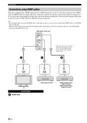
... skip the connection procedures from page 23 to 26. If your TV and other components have connected the HDMI cable(s) to the TV/STB OPTICAL DIGITAL IN jack on your TV to the HDMI jack(s) of this unit AUX 1 DVD IN OUT HDMI * This connection (except for simpler and easier ... jacks, use HDMI cables for a game console) is equipped with adhesive tape, etc. Rear panel of this unit. • This unit outputs analog video signal and analog/digital audio signals input at the video/component video jacks and analog/digital input jacks at the HDMI OUT jack. If your TV has a built-in...
... skip the connection procedures from page 23 to 26. If your TV and other components have connected the HDMI cable(s) to the TV/STB OPTICAL DIGITAL IN jack on your TV to the HDMI jack(s) of this unit AUX 1 DVD IN OUT HDMI * This connection (except for simpler and easier ... jacks, use HDMI cables for a game console) is equipped with adhesive tape, etc. Rear panel of this unit. • This unit outputs analog video signal and analog/digital audio signals input at the video/component video jacks and analog/digital input jacks at the HDMI OUT jack. If your TV has a built-in...
Owner's Manual
Page 27
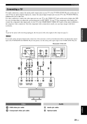
Rear panel of this unit COMPONENT VIDEO OUT TV/STB AUX 1 AUDIO IN DVD AUX 2 COAXIAL OPTICAL TV/STB AUX 1 DIGITAL IN Video input R L Component video input Analog audio output Optical digital output TV Video OSD video pin cable Component video pin cable Audio Audio pin cable Optical cable 23 En...TV/STB OPTICAL DIGITAL IN jack on this unit. PREPARATION Connections Connecting a TV For audio connection, connect the analog audio output jacks on your TV to the TV/STB AUDIO IN jacks on this unit to display the OSD for easy viewing when you adjust the system parameters in SET...
Rear panel of this unit COMPONENT VIDEO OUT TV/STB AUX 1 AUDIO IN DVD AUX 2 COAXIAL OPTICAL TV/STB AUX 1 DIGITAL IN Video input R L Component video input Analog audio output Optical digital output TV Video OSD video pin cable Component video pin cable Audio Audio pin cable Optical cable 23 En...TV/STB OPTICAL DIGITAL IN jack on this unit. PREPARATION Connections Connecting a TV For audio connection, connect the analog audio output jacks on your TV to the TV/STB AUDIO IN jacks on this unit to display the OSD for easy viewing when you adjust the system parameters in SET...
Owner's Manual
Page 28
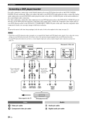
... in the supplied cable clamp (see page 28). If not, adjust the system settings of this unit. y To prevent the optical cable from being unplugged, affix the optical cable in addition to the coaxial digital audio connection. ANTENNA COMPONENT COMPONENT SUBWOOFER STB DVD/AUX 2 VIDEO IN AUX ...1 TV/STB AUX 1 AUDIO IN Rear panel of this unit. When you can only make an optical digital audio connection instead (see page 21). For video connection, connect the video output jack of your DVD player/...
... in the supplied cable clamp (see page 28). If not, adjust the system settings of this unit. y To prevent the optical cable from being unplugged, affix the optical cable in addition to the coaxial digital audio connection. ANTENNA COMPONENT COMPONENT SUBWOOFER STB DVD/AUX 2 VIDEO IN AUX ...1 TV/STB AUX 1 AUDIO IN Rear panel of this unit. When you can only make an optical digital audio connection instead (see page 21). For video connection, connect the video output jack of your DVD player/...
Owner's Manual
Page 29
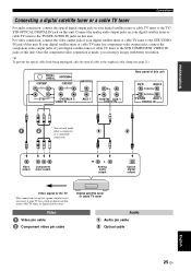
... y To prevent the optical cable from being unplugged, affix the optical cable in digital satellite tuner, cable TV tuner, or digital airwave tuner. Video Component output video output R L Analog audio output Optical digital output Video signal to the TV * This connection (except for a game console) ...21). ANTENNA COMPONENT COMPONENT SUBWOOFER STB DVD/AUX 2 VIDEO IN AUX 1 TV/STB AUX 1 AUDIO IN Rear panel of this unit DVD AUX 2 COAXIAL OPTICAL TV/STB AUX 1 DIGITAL IN * * * You can enjoy images with better resolution. For video connection, connect the video output jack...
... y To prevent the optical cable from being unplugged, affix the optical cable in digital satellite tuner, cable TV tuner, or digital airwave tuner. Video Component output video output R L Analog audio output Optical digital output Video signal to the TV * This connection (except for a game console) ...21). ANTENNA COMPONENT COMPONENT SUBWOOFER STB DVD/AUX 2 VIDEO IN AUX 1 TV/STB AUX 1 AUDIO IN Rear panel of this unit DVD AUX 2 COAXIAL OPTICAL TV/STB AUX 1 DIGITAL IN * * * You can enjoy images with better resolution. For video connection, connect the video output jack...
Owner's Manual
Page 30
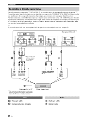
...pin cable Component video pin cable Digital airwave tuner Audio Audio pin cable Optical cable 26 En COMPONENT ANTENNA COMPONENT SUBWOOFER STB DVD/AUX 2 VIDEO IN AUX 1 TV/STB AUX 1 AUDIO IN Rear panel of this unit DVD AUX 2 COAXIAL OPTICAL TV/STB AUX 1 DIGITAL IN * * * You ...can enjoy both analog and digital broadcasts. Optical digital output Video signal to the TV/STB OPTICAL DIGITAL IN jack on the TV. For video connection, connect the...
...pin cable Component video pin cable Digital airwave tuner Audio Audio pin cable Optical cable 26 En COMPONENT ANTENNA COMPONENT SUBWOOFER STB DVD/AUX 2 VIDEO IN AUX 1 TV/STB AUX 1 AUDIO IN Rear panel of this unit DVD AUX 2 COAXIAL OPTICAL TV/STB AUX 1 DIGITAL IN * * * You ...can enjoy both analog and digital broadcasts. Optical digital output Video signal to the TV/STB OPTICAL DIGITAL IN jack on the TV. For video connection, connect the...

Owner's Manual
Page 31
PREPARATION Connections Connecting a portable audio player Connect the analog audio output jack on your portable audio player to the AUX 3 input jack on the front panel of this unit. Front panel of this unit AUX 3 INTELLIBEAM MIC AUX 3 INPUT VOLUME + STANDBY/ON Analog audio output Portable audio player Audio 3.5 mm stereo mini plug cable English 27 En
PREPARATION Connections Connecting a portable audio player Connect the analog audio output jack on your portable audio player to the AUX 3 input jack on the front panel of this unit. Front panel of this unit AUX 3 INTELLIBEAM MIC AUX 3 INPUT VOLUME + STANDBY/ON Analog audio output Portable audio player Audio 3.5 mm stereo mini plug cable English 27 En
Owner's Manual
Page 32
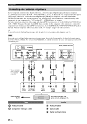
... VIDEO IN AUX 1 TV/STB AUX 1 AUDIO IN Rear panel of this unit DVD AUX 2 COAXIAL OPTICAL TV/STB AUX 1 DIGITAL IN * You can enjoy images with better resolution. Audio Audio pin cable Optical cable Digital audio pin cable 28 En Connections Connecting other external components If your..., etc. If your component to the TV Video Video pin cable Component video pin cable Video output R L Analog audio output Optical digital output Coaxial digital output DVD player/recorder, VCR, game console, CD player, etc. y To prevent the optical cable from being unplugged, affix the ...
... VIDEO IN AUX 1 TV/STB AUX 1 AUDIO IN Rear panel of this unit DVD AUX 2 COAXIAL OPTICAL TV/STB AUX 1 DIGITAL IN * You can enjoy images with better resolution. Audio Audio pin cable Optical cable Digital audio pin cable 28 En Connections Connecting other external components If your..., etc. If your component to the TV Video Video pin cable Component video pin cable Video output R L Analog audio output Optical digital output Coaxial digital output DVD player/recorder, VCR, game console, CD player, etc. y To prevent the optical cable from being unplugged, affix the ...

Owner's Manual
Page 33
... 1 System connector 5 cable System Monaural connector input Audio 5 Subwoofer pin cable Subwoofer English 29 En When connecting a Yamaha subwoofer equipped with a SYSTEM CONNECTOR terminal, connect it to the SUBWOOFER jack on this unit (U.S.A. and Canada models) FM75 UNBAL. To output sound from ...system type connection, changing the power mode of this unit. PREPARATION Connections Connecting a subwoofer Connect the monaural input jack on your subwoofer and then run AUTO SETUP (see page 37) or select SWFR for BASS OUT in SUBWOOFER SET (see page 82). COMPONENT Rear panel...
... 1 System connector 5 cable System Monaural connector input Audio 5 Subwoofer pin cable Subwoofer English 29 En When connecting a Yamaha subwoofer equipped with a SYSTEM CONNECTOR terminal, connect it to the SUBWOOFER jack on this unit (U.S.A. and Canada models) FM75 UNBAL. To output sound from ...system type connection, changing the power mode of this unit. PREPARATION Connections Connecting a subwoofer Connect the monaural input jack on your subwoofer and then run AUTO SETUP (see page 37) or select SWFR for BASS OUT in SUBWOOFER SET (see page 82). COMPONENT Rear panel...
Owner's Manual
Page 34
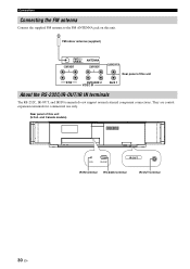
They are control expansion terminals for commercial use only. and Canada models) IR-OUT IR IN RS-232C IR-OUT IR IN terminal RS-232C terminal IR-OUT terminal 30 En Connections Connecting the FM antenna Connect the supplied FM antenna to the FM ANTENNA jack on this unit (U.S.A. FM indoor antenna (supplied) FM75 UNBAL. Rear panel of this unit STB DVD/AUX 2 VIDEO IN AUX 1 About the RS-232C/IR-OUT/IR IN terminals The RS-232C, IR-OUT, and IR IN terminals do not support normal external component connections. ANTENNA COMPONENT COMPONENT SUBWOOFER Rear panel of this unit.
They are control expansion terminals for commercial use only. and Canada models) IR-OUT IR IN RS-232C IR-OUT IR IN terminal RS-232C terminal IR-OUT terminal 30 En Connections Connecting the FM antenna Connect the supplied FM antenna to the FM ANTENNA jack on this unit (U.S.A. FM indoor antenna (supplied) FM75 UNBAL. Rear panel of this unit STB DVD/AUX 2 VIDEO IN AUX 1 About the RS-232C/IR-OUT/IR IN terminals The RS-232C, IR-OUT, and IR IN terminals do not support normal external component connections. ANTENNA COMPONENT COMPONENT SUBWOOFER Rear panel of this unit.
Owner's Manual
Page 35
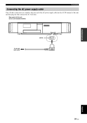
and Canada models) To the AC wall outlet IR-OUT AC IN PREPARATION English 31 En Rear panel of this unit (U.S.A. Connections Connecting the AC power supply cable Once all other connections are complete, plug one end of the AC power supply cable into the AC IN terminal of this unit and then plug the other end into the AC wall outlet.
and Canada models) To the AC wall outlet IR-OUT AC IN PREPARATION English 31 En Rear panel of this unit (U.S.A. Connections Connecting the AC power supply cable Once all other connections are complete, plug one end of the AC power supply cable into the AC IN terminal of this unit and then plug the other end into the AC wall outlet.

Owner's Manual
Page 37
The volume level appears in the standby mode, only STANDBY/ON on the front panel or on the remote control is turned on. STANDBY/ON or STANDBY/ON Front panel Remote control VOLUME 30 Current volume level DVD MY SUR Current input source Current beam mode 33 En English and Canada models) 1... Turning on the power of this unit is operational, and the other control buttons on the front panel or on the remote control are displayed. Note When this unit is in the front panel display, and the current input source and beam mode are not operational until the power of this unit...
The volume level appears in the standby mode, only STANDBY/ON on the front panel or on the remote control is turned on. STANDBY/ON or STANDBY/ON Front panel Remote control VOLUME 30 Current volume level DVD MY SUR Current input source Current beam mode 33 En English and Canada models) 1... Turning on the power of this unit is operational, and the other control buttons on the front panel or on the remote control are displayed. Note When this unit is in the front panel display, and the current input source and beam mode are not operational until the power of this unit...

Owner's Manual
Page 38
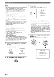
... screen appears on your TV screen and to turn on the power of this unit on your listening room. STANDBY/ON or STANDBY/ON Front panel Remote control 3 Turn on the power of this unit. MENU p p SET MENU . ;MEMORY ;AUTO SETUP ;MANUAL SETUP ;LANGUAGE SETUP [ ]/[ ]:Up/Down [ENTER]:Enter ...34 En TV/AV YSP 5 Press MENU. Once this is complete, you can enjoy real surround sound while watching TV in the comfort of your own home. 1 Check that the video input jack on your TV is connected to the VIDEO OUT...
... screen appears on your TV screen and to turn on the power of this unit on your listening room. STANDBY/ON or STANDBY/ON Front panel Remote control 3 Turn on the power of this unit. MENU p p SET MENU . ;MEMORY ;AUTO SETUP ;MANUAL SETUP ;LANGUAGE SETUP [ ]/[ ]:Up/Down [ENTER]:Enter ...34 En TV/AV YSP 5 Press MENU. Once this is complete, you can enjoy real surround sound while watching TV in the comfort of your own home. 1 Check that the video input jack on your TV is connected to the VIDEO OUT...
Owner's Manual
Page 40
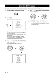
... . ;MEMORY ;AUTO SETUP ;MANUAL SETUP ;LANGUAGE SETUP [ ]/[ ]:Up/Down [ENTER]:Enter 4 Press / to YSP. ENTER ENTER ;LANGUAGE SETUP . ENGLISH DEUTSCH Francais ESPANOL ITALIANO NEDERLANDS [ ]/[ ]:Select [ENTER]:Return p p 36 En TV/AV YSP 2 Press MENU. The following operations while viewing information in the front panel display. 3 Press / to select LANGUAGE SETUP, and press ENTER.
... . ;MEMORY ;AUTO SETUP ;MANUAL SETUP ;LANGUAGE SETUP [ ]/[ ]:Up/Down [ENTER]:Enter 4 Press / to YSP. ENTER ENTER ;LANGUAGE SETUP . ENGLISH DEUTSCH Francais ESPANOL ITALIANO NEDERLANDS [ ]/[ ]:Select [ENTER]:Return p p 36 En TV/AV YSP 2 Press MENU. The following operations while viewing information in the front panel display. 3 Press / to select LANGUAGE SETUP, and press ENTER.

Owner's Manual
Page 42
...set VOLUME CROSSOVER HIGH CUT the crossover/high-cut frequency controls is sensitive to the INTELLIBEAM MIC jack on the front panel. 3 Place the IntelliBeam microphone on a conventional clockface and set the volume between the IntelliBeam microphone and the walls... position. AUTO SETUP (IntelliBeam) Installing the IntelliBeam microphone The supplied IntelliBeam microphone collects and analyzes the sound that this unit. STANDBY/ON or STANDBY/ON Front panel Remote control 2 Connect the supplied IntelliBeam microphone to heat. - Do not place the IntelliBeam microphone more...
...set VOLUME CROSSOVER HIGH CUT the crossover/high-cut frequency controls is sensitive to the INTELLIBEAM MIC jack on the front panel. 3 Place the IntelliBeam microphone on a conventional clockface and set the volume between the IntelliBeam microphone and the walls... position. AUTO SETUP (IntelliBeam) Installing the IntelliBeam microphone The supplied IntelliBeam microphone collects and analyzes the sound that this unit. STANDBY/ON or STANDBY/ON Front panel Remote control 2 Connect the supplied IntelliBeam microphone to heat. - Do not place the IntelliBeam microphone more...
Owner's Manual
Page 44
...screen shown in your listening environment (see page 45). 1 Press STANDBY/ON to turn on the varying conditions of the subwoofer. Open the curtains to YSP. 3 Press MENU. Run BEAM OPTIMZ only. 3. Steps 4 and 5 are curtains in step 5 is displayed on your TV. The following the ...power of your listening room, we recommend following screen appears on page 17. STANDBY/ON or STANDBY/ON Front panel Remote control 2 Set the operation mode selector to improve sound reflection. 2. If a subwoofer is connected to this unit is performing the AUTO SETUP procedure. • To...
...screen shown in your listening environment (see page 45). 1 Press STANDBY/ON to turn on the varying conditions of the subwoofer. Open the curtains to YSP. 3 Press MENU. Run BEAM OPTIMZ only. 3. Steps 4 and 5 are curtains in step 5 is displayed on your TV. The following the ...power of your listening room, we recommend following screen appears on page 17. STANDBY/ON or STANDBY/ON Front panel Remote control 2 Set the operation mode selector to improve sound reflection. 2. If a subwoofer is connected to this unit is performing the AUTO SETUP procedure. • To...
