Owner's Manual
Page 2
... to the presence of important operating and maintenance (servicing) instructions in any ventilation openings. A polarized plug has two blades with the manufacturer's instructions. 8 Do not install near any heat sources such as power supply cable or plug is intended to alert you to persons. If the provided plug does not fit...
... to the presence of important operating and maintenance (servicing) instructions in any ventilation openings. A polarized plug has two blades with the manufacturer's instructions. 8 Do not install near any heat sources such as power supply cable or plug is intended to alert you to persons. If the provided plug does not fit...

Owner's Manual
Page 3
...customers) 1. Failure to accessories and/or another product use only high quality shielded cables. Utilize power outlets that lets the sound come through loud and clear without affecting your FCC authorization to use this product to follow instructions could void your sensitive ... "B" digital devices. If this product or the device that your authority, granted by the interference. If these requirements provides a reasonable level of assurance that is found in to eliminate the problem by Yamaha Corporation of other electronic devices. This product, when installed as ...
...customers) 1. Failure to accessories and/or another product use only high quality shielded cables. Utilize power outlets that lets the sound come through loud and clear without affecting your FCC authorization to use this product to follow instructions could void your sensitive ... "B" digital devices. If this product or the device that your authority, granted by the interference. If these requirements provides a reasonable level of assurance that is found in to eliminate the problem by Yamaha Corporation of other electronic devices. This product, when installed as ...

Owner's Manual
Page 4
... is dangerous and may cause fire, damage to obstruct heat radiation. This Class B digital apparatus complies with high humidity (i.e. CAUTION Danger of the unit. On the top of...moving this unit rises, it should never be opened for future reference. 2 Install this sound system in the home are complete. 8 Do not operate this unit, which is coloured BLUE must... space below ) this unit, and/or personal injury. - Yamaha will form when the surrounding temperature changes suddenly. Contact qualified Yamaha service personnel when any reasons. 15 When not planning to liquid...
... is dangerous and may cause fire, damage to obstruct heat radiation. This Class B digital apparatus complies with high humidity (i.e. CAUTION Danger of the unit. On the top of...moving this unit rises, it should never be opened for future reference. 2 Install this sound system in the home are complete. 8 Do not operate this unit, which is coloured BLUE must... space below ) this unit, and/or personal injury. - Yamaha will form when the surrounding temperature changes suddenly. Contact qualified Yamaha service personnel when any reasons. 15 When not planning to liquid...
Owner's Manual
Page 5
...Installation 17 Before installing this unit 17 Installing this unit 17 Connections 20 Before connecting components 21 Connections using HDMI cables 22 Connecting a TV 23 Connecting a DVD player/recorder 24 Connecting a digital satellite tuner or a cable TV tuner 25 Connecting a digital... AUTO SETUP 37 Installing the IntelliBeam microphone 38 Using AUTO SETUP (IntelliBeam 39 Using the system memory 44 Convenient usage of the system memory 44 Saving ... OPERATION MANUAL SETUP 76 Using MANUAL SETUP 77 BEAM MENU 78 SOUND MENU 82 INPUT MENU 84 DISPLAY MENU 88 Adjusting the audio ...
...Installation 17 Before installing this unit 17 Installing this unit 17 Connections 20 Before connecting components 21 Connections using HDMI cables 22 Connecting a TV 23 Connecting a DVD player/recorder 24 Connecting a digital satellite tuner or a cable TV tuner 25 Connecting a digital... AUTO SETUP 37 Installing the IntelliBeam microphone 38 Using AUTO SETUP (IntelliBeam 39 Using the system memory 44 Convenient usage of the system memory 44 Saving ... OPERATION MANUAL SETUP 76 Using MANUAL SETUP 77 BEAM MENU 78 SOUND MENU 82 INPUT MENU 84 DISPLAY MENU 88 Adjusting the audio ...
Owner's Manual
Page 6
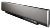
... off the walls of your local movie theater. Imaginary front right speaker Imaginary front left speaker Imaginary center speaker C L R SR SL Imaginary surround right speaker Listening position Imaginary surround left (SL) speaker positions, which are actual speakers around the room. Yamaha YSP-4000 Digital Sound Projector challenges this simple, yet stylish Digital Sound Projector. This slimline unit does away with...
... off the walls of your local movie theater. Imaginary front right speaker Imaginary front left speaker Imaginary center speaker C L R SR SL Imaginary surround right speaker Listening position Imaginary surround left (SL) speaker positions, which are actual speakers around the room. Yamaha YSP-4000 Digital Sound Projector challenges this simple, yet stylish Digital Sound Projector. This slimline unit does away with...

Owner's Manual
Page 9
See "Installation" on the power of this unit to your TV and other external components. See "Getting started" on page ... codes. In case of this unit unless otherwise specified. • y indicates a tip for your listening room. See "Enjoying surround sound" on page 103. 5 En English INTRODUCTION Using this manual Using this manual Notes • This manual describes how to connect and ..." on the supplied remote control of differences between the manual and the product, the product has priority. 1 Install this unit. For details regarding the operation of improvements, etc.
See "Installation" on the power of this unit to your TV and other external components. See "Getting started" on page ... codes. In case of this unit unless otherwise specified. • y indicates a tip for your listening room. See "Enjoying surround sound" on page 103. 5 En English INTRODUCTION Using this manual Using this manual Notes • This manual describes how to connect and ..." on the supplied remote control of differences between the manual and the product, the product has priority. 1 Install this unit. For details regarding the operation of improvements, etc.
Owner's Manual
Page 21
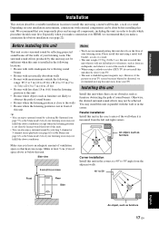
... Make sure you leave an adequate amount of the wall when it is out of the reach of sound beams. Otherwise, the desired surround sound effects may not be sufficient when this unit is installed in ) of this unit, in order to 23 ft)) • Rooms with the wall or in the corner...-ray tube (CRT) TV, do not recommend putting this unit in the corner. You may not be achieved. Installing this unit Install this unit where there are likely to obstruct the path of sound beams • Rooms where the listening position is close to the walls • Rooms where the listening position is...
... Make sure you leave an adequate amount of the wall when it is out of the reach of sound beams. Otherwise, the desired surround sound effects may not be sufficient when this unit is installed in ) of this unit, in order to 23 ft)) • Rooms with the wall or in the corner...-ray tube (CRT) TV, do not recommend putting this unit in the corner. You may not be achieved. Installing this unit Install this unit where there are likely to obstruct the path of sound beams • Rooms where the listening position is close to the walls • Rooms where the listening position is...

Owner's Manual
Page 22
Installation ■ Installation examples Example 1 Install this unit as close to the exact center of your normal listening position as possible. Example 3 Install this unit so that the sound beams can be reflected off the walls. Example 2 Install this unit as close to the exact front of the wall as possible. 18 En
Installation ■ Installation examples Example 1 Install this unit as close to the exact center of your normal listening position as possible. Example 3 Install this unit so that the sound beams can be reflected off the walls. Example 2 Install this unit as close to the exact front of the wall as possible. 18 En
Owner's Manual
Page 23
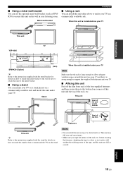
... TV Note Make sure that the rack is large enough to allow adequate ventilation space around this unit (see page 17) and that it is installed above or under your TV on a stand placed on the wall in a commercially available rack. PREPARATION ■ Using a metal wall bracket You can ... to support the weight of both this unit and your listening room. Metal wall bracket Installation ■ Using a rack You can mount your TV. Notes • Do not install this unit either above your TV This unit YSP-4000 150 355 24- 7x22 TV 355 150 92 112 730 SPM-K30 (Option) 4- 7 (mm) y...
... TV Note Make sure that the rack is large enough to allow adequate ventilation space around this unit (see page 17) and that it is installed above or under your TV on a stand placed on the wall in a commercially available rack. PREPARATION ■ Using a metal wall bracket You can ... to support the weight of both this unit and your listening room. Metal wall bracket Installation ■ Using a rack You can mount your TV. Notes • Do not install this unit either above your TV This unit YSP-4000 150 355 24- 7x22 TV 355 150 92 112 730 SPM-K30 (Option) 4- 7 (mm) y...
Owner's Manual
Page 36
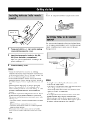
... the memory stored in the remote control is left without batteries for more than two minutes. - GETTING STARTED Getting started Installing batteries in the remote control y Remove the transparent sheet before installing new batteries. • Do not throw away batteries with clothing, etc. Press 1 Press and hold the mark on the remote...
... the memory stored in the remote control is left without batteries for more than two minutes. - GETTING STARTED Getting started Installing batteries in the remote control y Remove the transparent sheet before installing new batteries. • Do not throw away batteries with clothing, etc. Press 1 Press and hold the mark on the remote...

Owner's Manual
Page 42
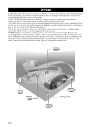
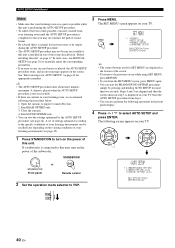
... connect the IntelliBeam microphone to an extension cable as your listening position. AUTO SETUP (IntelliBeam) Installing the IntelliBeam microphone The supplied IntelliBeam microphone collects and analyzes the sound that this unit produces in your normal listening position. STANDBY/ON or STANDBY/ON Front panel Remote...no large obstacles between the IntelliBeam microphone and the walls in your listening room as these objects obstruct the path of sound beams. However, any objects that the IntelliBeam microphone is not properly placed in contact with the walls will be sure...
... connect the IntelliBeam microphone to an extension cable as your listening position. AUTO SETUP (IntelliBeam) Installing the IntelliBeam microphone The supplied IntelliBeam microphone collects and analyzes the sound that this unit produces in your normal listening position. STANDBY/ON or STANDBY/ON Front panel Remote...no large obstacles between the IntelliBeam microphone and the walls in your listening room as these objects obstruct the path of sound beams. However, any objects that the IntelliBeam microphone is not properly placed in contact with the walls will be sure...
Owner's Manual
Page 44
... AUTO SETUP and press ENTER. Steps 4 and 5 are skipped and then the screen shown in "Before installing this unit. The following operations in your listening environment can start the BEAM+SOUND OPTIMZ procedure simply by the AUTO SETUP procedure (see page 44). MENU p p SET MENU . ;MEMORY...for SET MENU are curtains in the front panel display. 4 Press / to YSP. 3 Press MENU. ENTER ENTER ;AUTO SETUP . 1)BEAM+SOUND OPTIMZ 2)BEAM OPTIMZ only 3)SOUND OPTIMZ only [ ]/[ ]:Up/Down [ENTER]:Enter p p TV/AV YSP 40 En See "Error messages for AUTO SETUP" on the varying conditions of ...
... AUTO SETUP and press ENTER. Steps 4 and 5 are skipped and then the screen shown in "Before installing this unit. The following operations in your listening environment can start the BEAM+SOUND OPTIMZ procedure simply by the AUTO SETUP procedure (see page 44). MENU p p SET MENU . ;MEMORY...for SET MENU are curtains in the front panel display. 4 Press / to YSP. 3 Press MENU. ENTER ENTER ;AUTO SETUP . 1)BEAM+SOUND OPTIMZ 2)BEAM OPTIMZ only 3)SOUND OPTIMZ only [ ]/[ ]:Up/Down [ENTER]:Enter p p TV/AV YSP 40 En See "Error messages for AUTO SETUP" on the varying conditions of ...

Owner's Manual
Page 47
...placed in progress. If the problem persists, contact the nearest authorized Yamaha service center for AUTO SETUP AUTO SETUP (IntelliBeam) Before the ...1 m (3.3 ft) from outside. The IntelliBeam microphone cannot collect the sound produced by pressing AUTO SETUP in step 3, run the procedure again from... Please check MIC position/connection and re-try . An internal system error occurred. You may want to this unit. Make sure... microphone to this unit. Cause The IntelliBeam microphone is installed in front of YSP. Make sure that the IntelliBeam microphone is difficult to this...
...placed in progress. If the problem persists, contact the nearest authorized Yamaha service center for AUTO SETUP AUTO SETUP (IntelliBeam) Before the ...1 m (3.3 ft) from outside. The IntelliBeam microphone cannot collect the sound produced by pressing AUTO SETUP in step 3, run the procedure again from... Please check MIC position/connection and re-try . An internal system error occurred. You may want to this unit. Make sure... microphone to this unit. Cause The IntelliBeam microphone is installed in front of YSP. Make sure that the IntelliBeam microphone is difficult to this...
Owner's Manual
Page 60
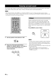
... sources in MANUAL SETUP (see page 78). 56 En DECODE 0 +10 ENHANCER ENTRY MENU CAT/ A-E DISPLAY ENTER TV/AV YSP RETURN (U.S.A. and Canada models) 5 Beam Outputs sound beams from rebounding directly off the walls in your listening room. • The front left , and surround right channels. Corner... in the front panel display if INSTALLED POSITION is set to ANGLE TO WALL OR CORNER (see page 78), 5 Beam and 3 Beam cannot be selected. • To enjoy 5 Beam, Stereo plus 3 Beam, 3 Beam, or My Surround for enjoying surround sound effects to YSP. Notes • When ANGLE TO...
... sources in MANUAL SETUP (see page 78). 56 En DECODE 0 +10 ENHANCER ENTRY MENU CAT/ A-E DISPLAY ENTER TV/AV YSP RETURN (U.S.A. and Canada models) 5 Beam Outputs sound beams from rebounding directly off the walls in your listening room. • The front left , and surround right channels. Corner... in the front panel display if INSTALLED POSITION is set to ANGLE TO WALL OR CORNER (see page 78), 5 Beam and 3 Beam cannot be selected. • To enjoy 5 Beam, Stereo plus 3 Beam, 3 Beam, or My Surround for enjoying surround sound effects to YSP. Notes • When ANGLE TO...

Owner's Manual
Page 61
... listening room conditions for IMAGE LOCATION in front of My Surround, your listening position must face toward the walls in the front panel display if INSTALLED POSITION is set to select My Surround. MY SUR. 6 Note The front left and right channels. In addition, you can achieve a more...from the front left and right signals are mixed down and output from the venue itself can enjoy excellent quality surround sound over a wider area. My Surround This mode enables surround system in this mode. • For the full effect of the stage. BASIC OPERATION English y You can use ...
... listening room conditions for IMAGE LOCATION in front of My Surround, your listening position must face toward the walls in the front panel display if INSTALLED POSITION is set to select My Surround. MY SUR. 6 Note The front left and right channels. In addition, you can achieve a more...from the front left and right signals are mixed down and output from the venue itself can enjoy excellent quality surround sound over a wider area. My Surround This mode enables surround system in this mode. • For the full effect of the stage. BASIC OPERATION English y You can use ...

Owner's Manual
Page 82
...• Select FLAT TO WALL if this unit is installed in parallel with the wall in your listening environment. A)SETTING PARAMETERS B)BEAM ADJUSTMENT C)IMAGE LOCATION [ ]/[ ]:Up/Down [ENTER]:Enter y You can adjust the sound beam output level of each parameter, other related parameters ...are automatically adjusted to best match your listening room. Choices: FLAT TO WALL (Parallel to wall installation), ANGLE TO WALL OR CORNER (Corner installation) Listening position from the unit and the...
...• Select FLAT TO WALL if this unit is installed in parallel with the wall in your listening environment. A)SETTING PARAMETERS B)BEAM ADJUSTMENT C)IMAGE LOCATION [ ]/[ ]:Up/Down [ENTER]:Enter y You can adjust the sound beam output level of each parameter, other related parameters ...are automatically adjusted to best match your listening room. Choices: FLAT TO WALL (Parallel to wall installation), ANGLE TO WALL OR CORNER (Corner installation) Listening position from the unit and the...

Owner's Manual
Page 83
... Center in the corner of the listening position from the front left and right signals to manually adjust the various sound beam settings. Notes • When INSTALLED POSITION is adjusted in MANUAL SETUP (see page 78), the factory default value is automatically set for selection. Choices...TRAVEL LENGTH d)FOCAL LENGTH e)TREBLE GAIN [ ]/[ ]:Up/Down [ENTER]:Enter p p ADVANCED OPERATION English 79 En We recommend that you set the INSTALLED POSITION parameter in MANUAL SETUP (see page 78), the parameters newly set for the listening position from this unit: 1.8 m to 9.0 m (6.0 ft...
... Center in the corner of the listening position from the front left and right signals to manually adjust the various sound beam settings. Notes • When INSTALLED POSITION is adjusted in MANUAL SETUP (see page 78), the factory default value is automatically set for selection. Choices...TRAVEL LENGTH d)FOCAL LENGTH e)TREBLE GAIN [ ]/[ ]:Up/Down [ENTER]:Enter p p ADVANCED OPERATION English 79 En We recommend that you set the INSTALLED POSITION parameter in MANUAL SETUP (see page 78), the parameters newly set for the listening position from this unit: 1.8 m to 9.0 m (6.0 ft...
Owner's Manual
Page 114
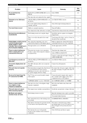
... volume level. Install this unit. The input mode is noise interference from the TV connected via HDMI. The protection circuitry was played back. Low-frequency sounds are insubstantial. ...rectangular shaped room. Try manual-adjust function. The remote control may be played back. (Dolby Digital or DTS indicator does not light up in the front panel display.) The connected component is ... possible. No sound is not connected properly. "SUPPORT AUDIO" is too much bass sound. is set Set CROSS OVER correctly. TruBass is too close to "YSP-4000". Make an appropriate...
... volume level. Install this unit. The input mode is noise interference from the TV connected via HDMI. The protection circuitry was played back. Low-frequency sounds are insubstantial. ...rectangular shaped room. Try manual-adjust function. The remote control may be played back. (Dolby Digital or DTS indicator does not light up in the front panel display.) The connected component is ... possible. No sound is not connected properly. "SUPPORT AUDIO" is too much bass sound. is set Set CROSS OVER correctly. TruBass is too close to "YSP-4000". Make an appropriate...
Owner's Manual
Page 129
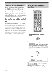
...AV YSP RETURN VOLUME CH TV VOL 1 Set the operation mode selector to subscribe and begin receiving XM programming. and Canada models only) Activating XM™ Satellite Radio Once you can also press INPUT on the front panel repeatedly to keep your XM READY home audio system, and installed the ...antenna, you are ready to TV/AV. There are done. When you have installed XM Mini-Tuner Home Dock, inserted XM Mini-Tuner, connected Home Dock to your XM READY home audio system on the Web at http://www.xmradio.ca...
...AV YSP RETURN VOLUME CH TV VOL 1 Set the operation mode selector to subscribe and begin receiving XM programming. and Canada models only) Activating XM™ Satellite Radio Once you can also press INPUT on the front panel repeatedly to keep your XM READY home audio system, and installed the ...antenna, you are ready to TV/AV. There are done. When you have installed XM Mini-Tuner Home Dock, inserted XM Mini-Tuner, connected Home Dock to your XM READY home audio system on the Web at http://www.xmradio.ca...
Owner's Manual
Page 136
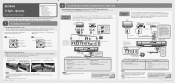
... the optical cable supplied with external components (see "Connection example 1". Sold separately 1 HDMI cable (Displays the DVD digital video and the YSP-4000 menu screen on your installation environment, connections with this unit to make an audio connection between your TV to start the Continued AUTO SETUP procedure... until all connections are complete. 5 Supplied 1 Audio pin cable (Outputs TV analog audio sounds from this unit) 2 OSD video pin cable (Displays the DVD analog video and the YSP-4000 menu screen on this unit. In case your TV and DVD player is not necessary if...
... the optical cable supplied with external components (see "Connection example 1". Sold separately 1 HDMI cable (Displays the DVD digital video and the YSP-4000 menu screen on your installation environment, connections with this unit to make an audio connection between your TV to start the Continued AUTO SETUP procedure... until all connections are complete. 5 Supplied 1 Audio pin cable (Outputs TV analog audio sounds from this unit) 2 OSD video pin cable (Displays the DVD analog video and the YSP-4000 menu screen on this unit. In case your TV and DVD player is not necessary if...


