Owners Manual
Page 2
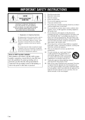
...type plug. Servicing is intended to alert you to the presence of important operating and maintenance (servicing) instructions in particular, specifies that the cable ground shall be of sufficient magnitude to constitute a risk of electric shock to the presence of time. 14 Refer all instructions. 5 ... Symbols The lightning flash with arrowhead symbol, within the product's enclosure that may be connected to the grounding system of cable entry as practical. 1 Read these instructions. 2 Keep these instructions. 3 Heed all warnings. 4 Follow all servicing to qualified service personnel.
...type plug. Servicing is intended to alert you to the presence of important operating and maintenance (servicing) instructions in particular, specifies that the cable ground shall be of sufficient magnitude to constitute a risk of electric shock to the presence of time. 14 Refer all instructions. 5 ... Symbols The lightning flash with arrowhead symbol, within the product's enclosure that may be connected to the grounding system of cable entry as practical. 1 Read these instructions. 2 Keep these instructions. 3 Heed all warnings. 4 Follow all servicing to qualified service personnel.
Owners Manual
Page 3
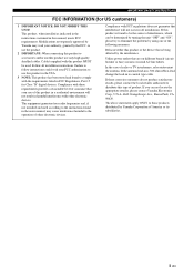
...harmful interference with the requirements listed in the users manual, may void your authority, granted by Yamaha Corporation of interference, which can not locate the appropriate retailer, please contact Yamaha Electronics Corp., U.S.A. 6660 Orangethorpe Ave., Buena Park, CA 90620. The above statements apply ...environment will not occur in the USA. 3 NOTE: This product has been tested and found to use only high quality shielded cables. Follow all installations. Compliance with FCC regulations does not guarantee that your FCC authorization to use this product to eliminate the ...
...harmful interference with the requirements listed in the users manual, may void your authority, granted by Yamaha Corporation of interference, which can not locate the appropriate retailer, please contact Yamaha Electronics Corp., U.S.A. 6660 Orangethorpe Ave., Buena Park, CA 90620. The above statements apply ...environment will not occur in the USA. 3 NOTE: This product has been tested and found to use only high quality shielded cables. Follow all installations. Compliance with FCC regulations does not guarantee that your FCC authorization to use this product to eliminate the ...
Owners Manual
Page 4
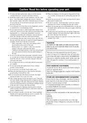
.... 1 To assure the finest performance, please read this unit with a newspaper, tablecloth, curtain, etc. this unit, do not place: - Yamaha will form when the surrounding temperature changes suddenly. vacation), disconnect the AC power plug from the wall outlet. 19 Condensation will not be exposed to...standby mode, and disconnect the power supply cable from the wall outlet. 16 Install this unit, and/or personal injury. Cet appareil numérique de la classe B est conforme à la norme NMB-003 du Canada. Contact qualified Yamaha service personnel when any reasons. 15 When...
.... 1 To assure the finest performance, please read this unit with a newspaper, tablecloth, curtain, etc. this unit, do not place: - Yamaha will form when the surrounding temperature changes suddenly. vacation), disconnect the AC power plug from the wall outlet. 19 Condensation will not be exposed to...standby mode, and disconnect the power supply cable from the wall outlet. 16 Install this unit, and/or personal injury. Cet appareil numérique de la classe B est conforme à la norme NMB-003 du Canada. Contact qualified Yamaha service personnel when any reasons. 15 When...
Owners Manual
Page 5
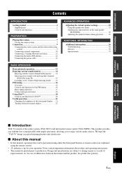
... the center system and the subwoofer/system control 9 Connecting external components 10 Connecting a Yamaha iPod universal dock 12 Connecting the indoor FM antenna 12 Connecting the power cable 12 BASIC OPERATION Basic playback operation 13 Enjoying various sound features 14 Enjoying realistic sounds ... tuning operation 17 Using station preset feature 18 Using iPod 20 Controls and functions for your operation. We hope the "YAS-70" brings you to enjoy various audio sources. INTRODUCTION PREPARATION Contents INTRODUCTION Getting started 2 Supplied parts 2 Controls and functions...
... the center system and the subwoofer/system control 9 Connecting external components 10 Connecting a Yamaha iPod universal dock 12 Connecting the indoor FM antenna 12 Connecting the power cable 12 BASIC OPERATION Basic playback operation 13 Enjoying various sound features 14 Enjoying realistic sounds ... tuning operation 17 Using station preset feature 18 Using iPod 20 Controls and functions for your operation. We hope the "YAS-70" brings you to enjoy various audio sources. INTRODUCTION PREPARATION Contents INTRODUCTION Getting started 2 Supplied parts 2 Controls and functions...
Owners Manual
Page 6
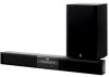
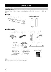
...-sided tape (Small, 4 pieces) x 1 Double-sided tape (Large, 2 pieces) x 2 Note The form of the following parts. ■ Units Center system (YAS-70CU) x 1 Subwoofer/system control (YAS-70SPX) x 1 ■ Accessories System control cable (4 m) x 1 Spacer x 2 Speaker cable (4 m) x 2 Remote control x 1 STANDBY/ON MOVIE MUSIC SPORTS GAME INPUT 1 INPUT 2 INPUT 3 DOCK FM INPUT VOLUME MENU MUTE A-E A-E ENTER PRESET...
...-sided tape (Small, 4 pieces) x 1 Double-sided tape (Large, 2 pieces) x 2 Note The form of the following parts. ■ Units Center system (YAS-70CU) x 1 Subwoofer/system control (YAS-70SPX) x 1 ■ Accessories System control cable (4 m) x 1 Spacer x 2 Speaker cable (4 m) x 2 Remote control x 1 STANDBY/ON MOVIE MUSIC SPORTS GAME INPUT 1 INPUT 2 INPUT 3 DOCK FM INPUT VOLUME MENU MUTE A-E A-E ENTER PRESET...

Owners Manual
Page 12
... weak materials such as short screws, nails, or two-sided tape, may fall . • When connecting the center system, fix the speaker cables in personal injury. 1 Attach the supplied mounting template on the screws using commercially available screws (#8, Diameter: 7.5 mm or more (9/32" or ... can choose either the side A or the side B. Using clamps other than specified screws, such as plaster or veneered woods. Yamaha will bear no responsibility for any accidents caused by a qualified contractor or dealer personnel. For narrow space For wide space Large doublesided...
... weak materials such as short screws, nails, or two-sided tape, may fall . • When connecting the center system, fix the speaker cables in personal injury. 1 Attach the supplied mounting template on the screws using commercially available screws (#8, Diameter: 7.5 mm or more (9/32" or ... can choose either the side A or the side B. Using clamps other than specified screws, such as plaster or veneered woods. Yamaha will bear no responsibility for any accidents caused by a qualified contractor or dealer personnel. For narrow space For wide space Large doublesided...
Owners Manual
Page 13
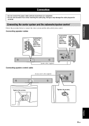
... to the speaker jack of the same color. Tighten the screws. Doing so may damage the cable plug and/or terminal. Connect the cable plug to the speaker jack of the same color. Connecting system control cable Speaker cables (supplied) SYSTEM CONNECTOR FM 75Ω UNBAL 3 L ANTENNA 1 2 DOCK R ANALOG INPUT OPTICAL COAXIAL R L SPEAKERS System...
... to the speaker jack of the same color. Tighten the screws. Doing so may damage the cable plug and/or terminal. Connect the cable plug to the speaker jack of the same color. Connecting system control cable Speaker cables (supplied) SYSTEM CONNECTOR FM 75Ω UNBAL 3 L ANTENNA 1 2 DOCK R ANALOG INPUT OPTICAL COAXIAL R L SPEAKERS System...

Owners Manual
Page 14
...INPUT 1] OPTICAL jack Example 1: DVD player TV DVD player DIGITAL OUT (OPTICAL) Optical digital cable Example 2: TV game console Game console TV OPTICAL DIGITAL OUTPUT Optical digital cable [INPUT 2] COAXIAL jack SYSTEM CONNECTOR FM 75Ω UNBAL 3 L ANTENNA 1 2 DOCK... FM 75Ω UNBAL 3 L ANTENNA 1 2 DOCK R ANALOG INPUT OPTICAL COAXIAL R L SPEAKERS CD player COAXIAL DIGITAL OUTPUT Coaxial digital cable SYSTEM CONNECTOR FM 75Ω UNBAL 3 L ANTENNA 1 2 DOCK R ANALOG INPUT OPTICAL COAXIAL R L SPEAKERS 10 En Connection Connecting external ...
...INPUT 1] OPTICAL jack Example 1: DVD player TV DVD player DIGITAL OUT (OPTICAL) Optical digital cable Example 2: TV game console Game console TV OPTICAL DIGITAL OUTPUT Optical digital cable [INPUT 2] COAXIAL jack SYSTEM CONNECTOR FM 75Ω UNBAL 3 L ANTENNA 1 2 DOCK... FM 75Ω UNBAL 3 L ANTENNA 1 2 DOCK R ANALOG INPUT OPTICAL COAXIAL R L SPEAKERS CD player COAXIAL DIGITAL OUTPUT Coaxial digital cable SYSTEM CONNECTOR FM 75Ω UNBAL 3 L ANTENNA 1 2 DOCK R ANALOG INPUT OPTICAL COAXIAL R L SPEAKERS 10 En Connection Connecting external ...
Owners Manual
Page 16
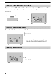
... universal dock This system is weak in your iPod using its dedicated cable. Connect a Yamaha iPod universal dock to connect a Yamaha iPod universal dock (such as the YDS-10, sold separately) where you can station your iPod and control playback of your area or you... want to improve the radio wave reception, we recommend that allows you to the DOCK terminal of the subwoofer/system control. Yamaha iPod universal dock (such as the YDS-10, sold separately) SYSTEM CONNECTOR FM 75Ω UNBAL 3 L ANTENNA 1 2 DOCK R ANALOG INPUT OPTICAL COAXIAL R L SPEAKERS...
... universal dock This system is weak in your iPod using its dedicated cable. Connect a Yamaha iPod universal dock to connect a Yamaha iPod universal dock (such as the YDS-10, sold separately) where you can station your iPod and control playback of your area or you... want to improve the radio wave reception, we recommend that allows you to the DOCK terminal of the subwoofer/system control. Yamaha iPod universal dock (such as the YDS-10, sold separately) SYSTEM CONNECTOR FM 75Ω UNBAL 3 L ANTENNA 1 2 DOCK R ANALOG INPUT OPTICAL COAXIAL R L SPEAKERS...
Owners Manual
Page 17
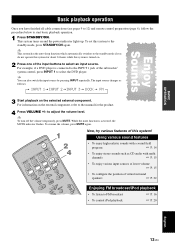
... system to select the DVD player. y This system has the auto-sleep function which automatically switches to the standby mode if you have finished all cable connections (see pages 9 to 12) and remote control preparation (page 6), follow the procedure below to start basic playback operation. 1 Press STANDBY/ON. The input source...
... system to select the DVD player. y This system has the auto-sleep function which automatically switches to the standby mode if you have finished all cable connections (see pages 9 to 12) and remote control preparation (page 6), follow the procedure below to start basic playback operation. 1 Press STANDBY/ON. The input source...
Owners Manual
Page 30
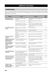
... or excessive static electricity. Make sure all cables are connected properly. Problem Cause Solution Power turns on this system, and then consult the nearest authorized Yamaha dealer or service center. The speaker cable may be shorted. The cables may be connected improperly. Cancel the mute ...function. Press sound field program button to minimum level. The speaker cable may be set to enable the sound...
... or excessive static electricity. Make sure all cables are connected properly. Problem Cause Solution Power turns on this system, and then consult the nearest authorized Yamaha dealer or service center. The speaker cable may be shorted. The cables may be connected improperly. Cancel the mute ...function. Press sound field program button to minimum level. The speaker cable may be set to enable the sound...

