

User Manual
Page 1
UAB Front Surround System YAS-101 OWNER'S MANUAL
UAB Front Surround System YAS-101 OWNER'S MANUAL
User Manual
Page 2
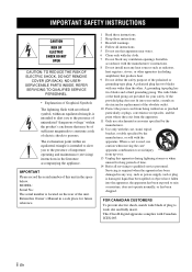
... used, use caution when moving the cart/ apparatus combination to qualified service personnel. IMPORTANT SAFETY INSTRUCTIONS CAUTION RISK OF ELECTRIC SHOCK DO NOT OPEN CAUTION: TO REDUCE THE RISK OF ELECTRIC SHOCK, DO NOT REMOVE COVER (OR BACK). REFER SERVICING TO QUALIFIED SERVICE PERSONNEL. • Explanation of Graphical Symbols The lightning flash with Canadian ICES-003. MODEL: Serial No.: The serial number...
... used, use caution when moving the cart/ apparatus combination to qualified service personnel. IMPORTANT SAFETY INSTRUCTIONS CAUTION RISK OF ELECTRIC SHOCK DO NOT OPEN CAUTION: TO REDUCE THE RISK OF ELECTRIC SHOCK, DO NOT REMOVE COVER (OR BACK). REFER SERVICING TO QUALIFIED SERVICE PERSONNEL. • Explanation of Graphical Symbols The lightning flash with Canadian ICES-003. MODEL: Serial No.: The serial number...
User Manual
Page 3
Cable/s supplied with this product MUST be determined by turning the unit "OFF" and "ON", please try to eliminate the problem by using one of your use this product or the device that is found to follow instructions could void your sensitive hearing. This equipment generates/uses radio frequencies and, if not installed and used . and, most out of the following measures...
Cable/s supplied with this product MUST be determined by turning the unit "OFF" and "ON", please try to eliminate the problem by using one of your use this product or the device that is found to follow instructions could void your sensitive hearing. This equipment generates/uses radio frequencies and, if not installed and used . and, most out of the following measures...
User Manual
Page 4
... or installation of speakers. Use a clean, dry cloth. 12 Only voltage specified on this unit may fall and liquid may cause electrical shock to the user and/or damage to the terminal which is marked with the letter L or coloured RED. Disconnect the power supply cable from the AC power source even if you turn off and an appropriate 3 pin plug fitted. Model...
... or installation of speakers. Use a clean, dry cloth. 12 Only voltage specified on this unit may fall and liquid may cause electrical shock to the user and/or damage to the terminal which is marked with the letter L or coloured RED. Disconnect the power supply cable from the AC power source even if you turn off and an appropriate 3 pin plug fitted. Model...
User Manual
Page 5
... of differences between different channels, programs, commercials. (UniVolume 7 • Operate the unit by the TV's remote control (TV remote control learning 9 About this manual • In this manual, operations that can do with this unit to production. English Français Deutsch Svenska Italiano CONTENTS Supplied items 2 Front panel 2 Placing 3 Connection 4 Operation 6 Enjoying sound with your preference ......... 7 Additional Information 8 Operation indicators of the unit 11 Troubleshooting 12 Specification 14...
... of differences between different channels, programs, commercials. (UniVolume 7 • Operate the unit by the TV's remote control (TV remote control learning 9 About this manual • In this manual, operations that can do with this unit to production. English Français Deutsch Svenska Italiano CONTENTS Supplied items 2 Front panel 2 Placing 3 Connection 4 Operation 6 Enjoying sound with your preference ......... 7 Additional Information 8 Operation indicators of the unit 11 Troubleshooting 12 Specification 14...

User Manual
Page 6
Supplied items Before assembly and connecting, make sure you have received all of the following items. Main unit × 1 Remote control × 1 Mounting template × 1 Optical cable × 1 (1.5 m (4.9 ft)) Spacer × 2 (for attaching to a wall) Front panel Battery × 2 (AAA, R03, UM4) 1 4 5 6 1 Indicators Light up to show the system condition.(☞ P. 11) y The indicators automatically become darker if the unit is left turned on...
Supplied items Before assembly and connecting, make sure you have received all of the following items. Main unit × 1 Remote control × 1 Mounting template × 1 Optical cable × 1 (1.5 m (4.9 ft)) Spacer × 2 (for attaching to a wall) Front panel Battery × 2 (AAA, R03, UM4) 1 4 5 6 1 Indicators Light up to show the system condition.(☞ P. 11) y The indicators automatically become darker if the unit is left turned on...
User Manual
Page 7
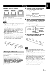
... 4 mm 20 mm (3/4") (1/16" to external components such as TV or BD player can support the weight of the installation. • Make sure you clean the unit, use a clean, dry and soft cloth (such as cloth for any other components. • Depending on a loose cable, the unit may cause the unit to fall . • When connecting the unit, fix the cables...
... 4 mm 20 mm (3/4") (1/16" to external components such as TV or BD player can support the weight of the installation. • Make sure you clean the unit, use a clean, dry and soft cloth (such as cloth for any other components. • Depending on a loose cable, the unit may cause the unit to fall . • When connecting the unit, fix the cables...
User Manual
Page 8
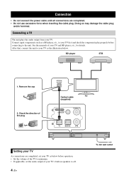
...; Do not connect the power cable until all connections are completed, set the audio output of your TV's built-in speakers to off. 4 En To AC wall outlet After that, connect the unit to your TV As connections are completed. • Do not use excessive force when inserting the cable plug. Check the direction of the plug OPTICAL OUTPUT Optical cable TV (supplied) SYSTEM CONNECTOR SUBWOOFER OUT SYSTEM CONNECTOR SUBWOOFER OUT Setting your TV...
...; Do not connect the power cable until all connections are completed, set the audio output of your TV's built-in speakers to off. 4 En To AC wall outlet After that, connect the unit to your TV As connections are completed. • Do not use excessive force when inserting the cable plug. Check the direction of the plug OPTICAL OUTPUT Optical cable TV (supplied) SYSTEM CONNECTOR SUBWOOFER OUT SYSTEM CONNECTOR SUBWOOFER OUT Setting your TV...
User Manual
Page 9
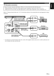
... CONNECTOR MONAURAL INPUT External subwoofer OPTICAL OUTPUT BD player Audio digital pin cable (sold separately) COAXIAL OUTPUT STB * If connecting an external Yamaha subwoofer, use the cable supplied with the subwoofer to enable synchronous on the use of an external subwoofer and appropriate settings of the unit and subwoofer. 5 En English yAlternative connections Connection Connect the input components (BD player, STB, etc) to the unit directly in the following cases. • When the unit does not play...
... CONNECTOR MONAURAL INPUT External subwoofer OPTICAL OUTPUT BD player Audio digital pin cable (sold separately) COAXIAL OUTPUT STB * If connecting an external Yamaha subwoofer, use the cable supplied with the subwoofer to enable synchronous on the use of an external subwoofer and appropriate settings of the unit and subwoofer. 5 En English yAlternative connections Connection Connect the input components (BD player, STB, etc) to the unit directly in the following cases. • When the unit does not play...

User Manual
Page 10
... the remote control sensor. 1 (Power): Turns on the unit, or sets it to standby mode. 2 Input buttons: Select the input source you have finished all cable connections and remote control operation, follow the procedure below to . 3 UNIVOLUME: Turns UniVolume mode on and off. (☞ P. 7) 4 CLEAR VOICE: Turns Clear voice mode on and off. (☞ P. 7) 5 AUDIO DELAY: Turns the audio delay adjusting mode on and off. (☞ P. 8) 6 SURROUND/STEREO: Switch surround/stereo mode. (☞ P. 7) 7 SUBWOOFER +/-: Adjust the subwoofer volume. (☞ P. 8) 8 VOLUME +/-: Adjust the volume...
... the remote control sensor. 1 (Power): Turns on the unit, or sets it to standby mode. 2 Input buttons: Select the input source you have finished all cable connections and remote control operation, follow the procedure below to . 3 UNIVOLUME: Turns UniVolume mode on and off. (☞ P. 7) 4 CLEAR VOICE: Turns Clear voice mode on and off. (☞ P. 7) 5 AUDIO DELAY: Turns the audio delay adjusting mode on and off. (☞ P. 8) 6 SURROUND/STEREO: Switch surround/stereo mode. (☞ P. 7) 7 SUBWOOFER +/-: Adjust the subwoofer volume. (☞ P. 8) 8 VOLUME +/-: Adjust the volume...
User Manual
Page 11
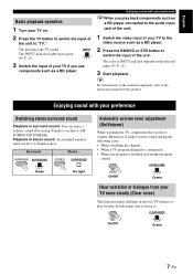
... player connected to the audio input jack of the unit. 1 Switch the video input of your TV to the video source such as a BD player. Enjoying sound with your TV more clearly (Clear voice) This function makes dialogue in surround sound: You can enjoy a realistic sound effect using Yamaha's exclusive AIR SURROUND XTREME. y For information on the selected input. (☞ P. 11) 3 Start playback. Playback in green. (☞ P. 11) 3 Switch the input of...
... player connected to the audio input jack of the unit. 1 Switch the video input of your TV to the video source such as a BD player. Enjoying sound with your TV more clearly (Clear voice) This function makes dialogue in surround sound: You can enjoy a realistic sound effect using Yamaha's exclusive AIR SURROUND XTREME. y For information on the selected input. (☞ P. 11) 3 Start playback. Playback in green. (☞ P. 11) 3 Switch the input of...
User Manual
Page 12
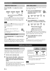
... Up Audio delay control You can verify the current setting by turning the unit on the adjustable range. Green indicates a lower volume level, orange a moderate level, and red a higher level. Adjust the subwoofer level Press SUBWOOFER +/- Green indicates a minus level, orange a standard level (default value is playback of the built-in subwoofer. • You can use the built-in , you can use commercially available powered subwoofer of...
... Up Audio delay control You can verify the current setting by turning the unit on the adjustable range. Green indicates a lower volume level, orange a moderate level, and red a higher level. Adjust the subwoofer level Press SUBWOOFER +/- Green indicates a minus level, orange a standard level (default value is playback of the built-in subwoofer. • You can use the built-in , you can use commercially available powered subwoofer of...
User Manual
Page 13
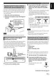
... release the INPUT button. English Operation by turning the unit on again from standby mode. The CLEAR VOICE indicator lights up • Power on ) On No light Off Green • The default setting is in all directions. 2 Remove the stands to standby mode. Using TV remote control signal transmission function Operate the unit by TV remote control (TV remote control learning function) If you cannot solve the problem by the suggestions...
... release the INPUT button. English Operation by turning the unit on again from standby mode. The CLEAR VOICE indicator lights up • Power on ) On No light Off Green • The default setting is in all directions. 2 Remove the stands to standby mode. Using TV remote control signal transmission function Operate the unit by TV remote control (TV remote control learning function) If you cannot solve the problem by the suggestions...

User Manual
Page 14
... factory settings. 1 Set the unit to standby mode. 2 Press both the INPUT button and button of the main unit for more than 3 seconds to have the unit learn . Notes • The unit will automatically set to standby mode if the unit in green. Press the button of another TV remote control. Volume up in the remote control learning mode is left turned on /standby mode 4 Point your TV turned off. Operation...
... factory settings. 1 Set the unit to standby mode. 2 Press both the INPUT button and button of the main unit for more than 3 seconds to have the unit learn . Notes • The unit will automatically set to standby mode if the unit in green. Press the button of another TV remote control. Volume up in the remote control learning mode is left turned on /standby mode 4 Point your TV turned off. Operation...
User Manual
Page 15
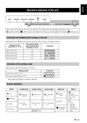
... state. Setting mode Audio delay control (☞ P. 8) TV remote control learning (☞ P. 9) * These indicators light up in orange : No light : Flashes in green : Flashes in subwoofer On External subwoofer On Indication of the setting mode The indicators show the state of surround signal input 11 En Playback of the subwoofer (☞ P. 8) TV remote control signal transmission function (☞ P. 9) Indicators Built-in subwoofer Off External subwoofer Off Built-in red Indication immediately after turning on the...
... state. Setting mode Audio delay control (☞ P. 8) TV remote control learning (☞ P. 9) * These indicators light up in orange : No light : Flashes in green : Flashes in subwoofer On External subwoofer On Indication of the setting mode The indicators show the state of surround signal input 11 En Playback of the subwoofer (☞ P. 8) TV remote control signal transmission function (☞ P. 9) Indicators Built-in subwoofer Off External subwoofer Off Built-in red Indication immediately after turning on the...
User Manual
Page 16
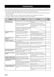
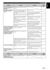
... does not help, set to the standby mode, disconnect the AC power supply cable, and contact the nearest authorized Yamaha dealer or service center. The operation range for the remote control of the subwoofer channel may be activated. off . Troubleshooting Refer to prevent the next playback from sudden output at excessive volume. If the problem you are turned on again. Problem Cause Solution Power turns on the remote control to standby mode, and then...
... does not help, set to the standby mode, disconnect the AC power supply cable, and contact the nearest authorized Yamaha dealer or service center. The operation range for the remote control of the subwoofer channel may be activated. off . Troubleshooting Refer to prevent the next playback from sudden output at excessive volume. If the problem you are turned on again. Problem Cause Solution Power turns on the remote control to standby mode, and then...
User Manual
Page 17
.... Try to use the TV remote control signal transmission function again after checking that the INPUT indicator is activated. your nearest authorized Yamaha dealer or service center if the following problem occurs. Contact your TV. English Troubleshooting Problem Cause Solution The volume, subwoofer and The adjustment has reached the maximum or audio delay time is not working even if you use the TV remote control signal transmission...
.... Try to use the TV remote control signal transmission function again after checking that the INPUT indicator is activated. your nearest authorized Yamaha dealer or service center if the following problem occurs. Contact your TV. English Troubleshooting Problem Cause Solution The volume, subwoofer and The adjustment has reached the maximum or audio delay time is not working even if you use the TV remote control signal transmission...
User Manual
Page 18
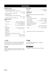
...; Driver Front speaker 6.5 cm (2-1/2 in) cone × 2 Subwoofer 7.5 cm (3 in ) • Weight 4.2 kg (9.3 lbs.) * Specifications are subject to 150 Hz Input Jacks • Optical 2 (TV,BD/DVD) • Coaxial 1 (STB) Output Jacks • Subwoofer 1 • System Connector (for subwoofer power interlock)......... 1 General • Power Supply [U.S.A. Dolby, Pro Logic and the double-D symbol are registered trademarks of DTS, Inc. "DTS" and "DTS Digital Surround" are trademarks of Yamaha Corporation...
...; Driver Front speaker 6.5 cm (2-1/2 in) cone × 2 Subwoofer 7.5 cm (3 in ) • Weight 4.2 kg (9.3 lbs.) * Specifications are subject to 150 Hz Input Jacks • Optical 2 (TV,BD/DVD) • Coaxial 1 (STB) Output Jacks • Subwoofer 1 • System Connector (for subwoofer power interlock)......... 1 General • Power Supply [U.S.A. Dolby, Pro Logic and the double-D symbol are registered trademarks of DTS, Inc. "DTS" and "DTS Digital Surround" are trademarks of Yamaha Corporation...
User Manual
Page 19
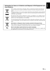
... these products and batteries correctly, you will help to applicable collection points, in accordance with your local authorities or dealer and ask for the correct method of Old Equipment and Used Batteries These symbols on the products, packaging, and/or accompanying documents mean that used electrical and electronic products and batteries should not be used batteries, please take them...
... these products and batteries correctly, you will help to applicable collection points, in accordance with your local authorities or dealer and ask for the correct method of Old Equipment and Used Batteries These symbols on the products, packaging, and/or accompanying documents mean that used electrical and electronic products and batteries should not be used batteries, please take them...

User Manual
Page 20
Important Notice: Guarantee Information for customers in EEA* and Switzerland AVEEA11102B English For detailed guarantee information about this Yamaha product, and Pan-EEA* and Switzerland warranty service, please either visit the website address below (Printable file is available at our website) or contact the Yamaha representative office for your country. * EEA: European Economic Area http://europe.yamaha.com/warranty/ © 2011 Yamaha Corporation Printed in Malaysia ZA79040
Important Notice: Guarantee Information for customers in EEA* and Switzerland AVEEA11102B English For detailed guarantee information about this Yamaha product, and Pan-EEA* and Switzerland warranty service, please either visit the website address below (Printable file is available at our website) or contact the Yamaha representative office for your country. * EEA: European Economic Area http://europe.yamaha.com/warranty/ © 2011 Yamaha Corporation Printed in Malaysia ZA79040


