Owner's Manual
Page 5
... Information on jacks and cable plugs 13 Connecting a TV monitor or projector 14 Connecting other components 15 Connecting a Yamaha iPod universal dock or Bluetooth™ wireless audio receiver 16 Using the VIDEO AUX jacks on the front panel .... 16 Connecting the FM and AM antennas 17 Connecting ...low frequency sound (tone control 22 Enjoying pure hi-fi sound 22 Using the sleep timer 22 Using your headphones 22 Displaying input signal information 23 Changing information on the front panel display .... 23 Enjoy the sound field programs 24 Selecting sound field programs 24 Enjoying ...
... Information on jacks and cable plugs 13 Connecting a TV monitor or projector 14 Connecting other components 15 Connecting a Yamaha iPod universal dock or Bluetooth™ wireless audio receiver 16 Using the VIDEO AUX jacks on the front panel .... 16 Connecting the FM and AM antennas 17 Connecting ...low frequency sound (tone control 22 Enjoying pure hi-fi sound 22 Using the sleep timer 22 Using your headphones 22 Displaying input signal information 23 Changing information on the front panel display .... 23 Enjoy the sound field programs 24 Selecting sound field programs 24 Enjoying ...
Owner's Manual
Page 6
... digital audio format signals capability ■ DOCK terminal • DOCK terminal to connect a Yamaha iPod universal dock (such as YDS-11, sold separately) ■ Automatic speaker setup features • "YPAO" (Yamaha Parametric Room Acoustic ...Optimizer) for automatically optimizing speaker outputs suitable for listening environments. ■ Other features • 192-kHz/24-bit D/A converter • Direct mode for pure hi-fi sound for standard, enhanced or highdefinition video as well as YBA-10, sold separately) or Bluetooth wireless audio receiver...
... digital audio format signals capability ■ DOCK terminal • DOCK terminal to connect a Yamaha iPod universal dock (such as YDS-11, sold separately) ■ Automatic speaker setup features • "YPAO" (Yamaha Parametric Room Acoustic ...Optimizer) for automatically optimizing speaker outputs suitable for listening environments. ■ Other features • 192-kHz/24-bit D/A converter • Direct mode for pure hi-fi sound for standard, enhanced or highdefinition video as well as YBA-10, sold separately) or Bluetooth wireless audio receiver...

Owner's Manual
Page 8
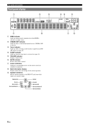
... programs (see page 21). K PROGRAM l / h Changes sound field programs (see page 22). S PORTABLE (VIDEO AUX) jack For connecting the audio output cable of an HDMI signal input to straight decoding mode (see page 29). F FM Sets the FM/AM tuner band to AM (see page 22). G AM Sets the FM/AM...
... programs (see page 21). K PROGRAM l / h Changes sound field programs (see page 22). S PORTABLE (VIDEO AUX) jack For connecting the audio output cable of an HDMI signal input to straight decoding mode (see page 29). F FM Sets the FM/AM tuner band to AM (see page 22). G AM Sets the FM/AM...
Owner's Manual
Page 9
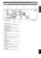
...AV 1 COAXIAL AV 2 COAXIAL (CD) AV 3 OPTICAL AV 4 AV 5 AV 6 AV OUT AUDIO1 AUDIO2 AUDIO OUT SURROUND BACK SUBWOOFER PRE OUT e fg hi j a DOCK terminal For connecting an optional Yamaha iPod universal dock (YDS11) or Bluetooth wireless audio receiver (YBA-10) (see page 11). f AV OUT Outputs audio/visual signals... ANTENNA jack For connecting supplied FM and AM antennas (see page 11). e AV 1-6 For connecting external components for audio inputs 1-2 (see page 14). h MONITOR OUT Outputs visual signals from a selected analog input source to an external component (see page 17)....
...AV 1 COAXIAL AV 2 COAXIAL (CD) AV 3 OPTICAL AV 4 AV 5 AV 6 AV OUT AUDIO1 AUDIO2 AUDIO OUT SURROUND BACK SUBWOOFER PRE OUT e fg hi j a DOCK terminal For connecting an optional Yamaha iPod universal dock (YDS11) or Bluetooth wireless audio receiver (YBA-10) (see page 11). f AV OUT Outputs audio/visual signals... ANTENNA jack For connecting supplied FM and AM antennas (see page 11). e AV 1-6 For connecting external components for audio inputs 1-2 (see page 14). h MONITOR OUT Outputs visual signals from a selected analog input source to an external component (see page 17)....
Owner's Manual
Page 10
... back L SW L CR SL SR SBL SB SBR Center Front R Surround R Surround back R Surround back df e SLEEP VOL. d SLEEP indicator Lights up while receiving a radio broadcast signal from which signals are available for the current operation. i Speaker indicators Indicate speaker terminals or the PRE OUT jack from an FM/ AM station (see page...
... back L SW L CR SL SR SBL SB SBR Center Front R Surround R Surround back R Surround back df e SLEEP VOL. d SLEEP indicator Lights up while receiving a radio broadcast signal from which signals are available for the current operation. i Speaker indicators Indicate speaker terminals or the PRE OUT jack from an FM/ AM station (see page...
Owner's Manual
Page 11
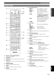
... Numeric keys Enter numbers. d SOURCE POWER Switches an external component on and off . Selects a Yamaha iPod universal dock/ Bluetooth wireless audio receiver connected to the previous screen or ends the menu screen. Selects a preset station. Confirms a selected ...l n r TRANSMIT CODE SET POWER SOURCE 1 1 5 SLEEP POWER HDMI 2 3 4 AV 2 3 4 AUDIO 6 1 2 V-AUX [ A ] [ B ] DOCK TUNER FM AM PRESET TUNING INFO MEMORY MOVIE ENHANCER SUR. b TRANSMIT Lights up when a signal is output from DOCK TUNER operations of this unit (see page 22). e SLEEP Switches the...
... Numeric keys Enter numbers. d SOURCE POWER Switches an external component on and off . Selects a Yamaha iPod universal dock/ Bluetooth wireless audio receiver connected to the previous screen or ends the menu screen. Selects a preset station. Confirms a selected ...l n r TRANSMIT CODE SET POWER SOURCE 1 1 5 SLEEP POWER HDMI 2 3 4 AV 2 3 4 AUDIO 6 1 2 V-AUX [ A ] [ B ] DOCK TUNER FM AM PRESET TUNING INFO MEMORY MOVIE ENHANCER SUR. b TRANSMIT Lights up when a signal is output from DOCK TUNER operations of this unit (see page 22). e SLEEP Switches the...

Owner's Manual
Page 14
...Place them at an equal distance from each other, ideally at the same distance as the Yamaha Active Servo Processing Subwoofer System. Place it halfway between the front left and right channel sound signals are used for effect and surround sounds. SL 60˚ SL 80˚ SBL SR... surround. To obtain a natural sound flow in the 5.1-channel speaker layout, place them slightly further back than in Dolby Digital and DTS signals. Connections Placing speakers This unit supports up to reduce reflections from the surround left and right speakers are about 1/4 of the TV and the...
...Place them at an equal distance from each other, ideally at the same distance as the Yamaha Active Servo Processing Subwoofer System. Place it halfway between the front left and right channel sound signals are used for effect and surround sounds. SL 60˚ SL 80˚ SBL SR... surround. To obtain a natural sound flow in the 5.1-channel speaker layout, place them slightly further back than in Dolby Digital and DTS signals. Connections Placing speakers This unit supports up to reduce reflections from the surround left and right speakers are about 1/4 of the TV and the...

Owner's Manual
Page 17
... jacks (white) L R AUDIO (red) COAXIAL jacks (orange) C COAXIAL OPTICAL jacks O OPTICAL To transmit conventional analog left and right audio signals. Connect red plugs to red jacks (R) and white plugs to the video monitor. ■ Video jacks Jack and cables VIDEO jacks VIDEO V ...This unit has the following input and output jacks. ADVANCED OPERATION ADDITIONAL INFORMATION APPENDIX English 13 En To transmit coaxial digital audio signals. Use HDMI cables. INTRODUCTION PREPARATION BASIC OPERATION Connections Information on HDMI connections (see page 23). Use stereo pin cables. ...
... jacks (white) L R AUDIO (red) COAXIAL jacks (orange) C COAXIAL OPTICAL jacks O OPTICAL To transmit conventional analog left and right audio signals. Connect red plugs to red jacks (R) and white plugs to the video monitor. ■ Video jacks Jack and cables VIDEO jacks VIDEO V ...This unit has the following input and output jacks. ADVANCED OPERATION ADDITIONAL INFORMATION APPENDIX English 13 En To transmit coaxial digital audio signals. Use HDMI cables. INTRODUCTION PREPARATION BASIC OPERATION Connections Information on HDMI connections (see page 23). Use stereo pin cables. ...

Owner's Manual
Page 18
Connecting to the AV input 1 allows you to switch an input source to the input signal format supported by the video monitor. Jacks on components Jacks on standby. TV, or projector (BD/DVD) HDMI OUT HDMI 1 HDMI 2 HD ANTENNA COMPONENT VIDEO ... a single key operation using the SCENE function (see page 44. ■ To connect component video monitor Note • Only video signals input from this unit. Note • When you use the AV input 1. Connections Connecting a TV monitor or projector Connect a video monitor such as a TV or projector to the video monitor, make...
Connecting to the AV input 1 allows you to switch an input source to the input signal format supported by the video monitor. Jacks on components Jacks on standby. TV, or projector (BD/DVD) HDMI OUT HDMI 1 HDMI 2 HD ANTENNA COMPONENT VIDEO ... a single key operation using the SCENE function (see page 44. ■ To connect component video monitor Note • Only video signals input from this unit. Note • When you use the AV input 1. Connections Connecting a TV monitor or projector Connect a video monitor such as a TV or projector to the video monitor, make...

Owner's Manual
Page 19
...Yamaha...Optical digital output Component video Coaxial digital output AV 1 (TV) AV 2 OPTICAL COMPONENT VIDEO COAXIAL Video Component video...AV 3 (CD) AV 4 COAXIAL VIDEO OPTICAL Video Composite output VIDEO Audio Analog audio output AV 5 AUDIO Video Composite output VIDEO Audio Analog audio output AV... jacks. Audio / video input (AV 1-6) Audio / video output (AV OUT) INTRODUCTION PREPARATION BASIC OPERATION ADVANCED...HDMI 3 HDMI 4 FRONT OPTICAL ( TV ) AV 1 COAXIAL AV 2 COAXIAL (CD) AV 3 OPTICAL AV 4 AV 5 AV 6 AV OUT AUDIO1 AUDIO2 AUDIO OUT HDMI input (HDMI 1-4)...
...Yamaha...Optical digital output Component video Coaxial digital output AV 1 (TV) AV 2 OPTICAL COMPONENT VIDEO COAXIAL Video Component video...AV 3 (CD) AV 4 COAXIAL VIDEO OPTICAL Video Composite output VIDEO Audio Analog audio output AV 5 AUDIO Video Composite output VIDEO Audio Analog audio output AV... jacks. Audio / video input (AV 1-6) Audio / video output (AV OUT) INTRODUCTION PREPARATION BASIC OPERATION ADVANCED...HDMI 3 HDMI 4 FRONT OPTICAL ( TV ) AV 1 COAXIAL AV 2 COAXIAL (CD) AV 3 OPTICAL AV 4 AV 5 AV 6 AV OUT AUDIO1 AUDIO2 AUDIO OUT HDMI input (HDMI 1-4)...
Owner's Manual
Page 20
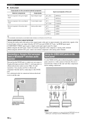
... front panel to connect a game console or a video camera to the analog audio terminal. An HDMI input signal, COMPONENT VIDEO input signal or digital audio input signal cannot be output. FM GND Using the VIDEO AUX jacks on the front panel Use the VIDEO AUX jacks... component with coaxial digital output Coaxial digital output AV 2 AV 3 (CD) COAXIAL COAXIAL External component with this unit and other components before making connections. You can connect a Yamaha iPod universal dock (YDS-11, sold separately) or a Bluetooth wireless audio receiver (YBA-10, sold separately). Be sure to...
... front panel to connect a game console or a video camera to the analog audio terminal. An HDMI input signal, COMPONENT VIDEO input signal or digital audio input signal cannot be output. FM GND Using the VIDEO AUX jacks on the front panel Use the VIDEO AUX jacks... component with coaxial digital output Coaxial digital output AV 2 AV 3 (CD) COAXIAL COAXIAL External component with this unit and other components before making connections. You can connect a Yamaha iPod universal dock (YDS-11, sold separately) or a Bluetooth wireless audio receiver (YBA-10, sold separately). Be sure to...

Owner's Manual
Page 25
...field programs are available for different usages, such as the initial factory settings. Input source Sound field program BD/DVD TV CD RADIO HDMI 1 AV 1 AV 3 TUNER Straight Straight Straight 7ch Enhancer y • When this unit by pressing the SCENE key. Switching remotely controlled external components linked to scene...If the condition is set "Decoder Mode" to "DTS" (see page 44). The following . 1) When only noise is output If a DTS bitstream signal is not properly input to this unit, only noise is displayed for a few seconds. Selecting a SCENE Press ISCENE (or kSCENE).
...field programs are available for different usages, such as the initial factory settings. Input source Sound field program BD/DVD TV CD RADIO HDMI 1 AV 1 AV 3 TUNER Straight Straight Straight 7ch Enhancer y • When this unit by pressing the SCENE key. Switching remotely controlled external components linked to scene...If the condition is set "Decoder Mode" to "DTS" (see page 44). The following . 1) When only noise is output If a DTS bitstream signal is not properly input to this unit, only noise is displayed for a few seconds. Selecting a SCENE Press ISCENE (or kSCENE).

Owner's Manual
Page 26
... • The tone control settings are not effective during playback in Direct mode. - Notes • When you connect headphones, no signals are output at the speaker terminals. • When multi-channel signals are processed, sounds in all channels are disabled in direct mode. • If you set the amount of the selected...
... • The tone control settings are not effective during playback in Direct mode. - Notes • When you connect headphones, no signals are output at the speaker terminals. • When multi-channel signals are processed, sounds in all channels are disabled in direct mode. • If you set the amount of the selected...

Owner's Manual
Page 27
... be displayed according to the input source. The following screen appears on the front panel display. See page 34 on messages displayed on input signals is displayed (see page 33). 2 Press nCursor k / n to display an error message. 4 To end the information display, press ... Program," the following information can be changed by pressing CINFO (or iINFO). INTRODUCTION PREPARATION Playback Displaying input signal information You can display information on audio/video signals input to this unit for each input source. The option menu for the selected input source is displayed....
... be displayed according to the input source. The following screen appears on the front panel display. See page 34 on messages displayed on input signals is displayed (see page 33). 2 Press nCursor k / n to display an error message. 4 To end the information display, press ... Program," the following information can be changed by pressing CINFO (or iINFO). INTRODUCTION PREPARATION Playback Displaying input signal information You can display information on audio/video signals input to this unit for each input source. The option menu for the selected input source is displayed....

Owner's Manual
Page 28
... programs ■ Selecting a sound field program on the front panel Press KPROGRAM l / h repeatedly to select a desired sound field program. ■ Selecting a sound field program with a Yamaha digital sound field processing (DSP) chip. Stereo reproduction Press jSTEREO repeatedly. When you play back the Dolby Digital Plus, Dolby TrueHD, DTS Express, DTS-HD... indicators on the name of the sound. 24 En Sound field program category Sci-Fi Program name Notes • Sound field programs are currently outputting signals with the concept of large-scale movie productions.
... programs ■ Selecting a sound field program on the front panel Press KPROGRAM l / h repeatedly to select a desired sound field program. ■ Selecting a sound field program with a Yamaha digital sound field processing (DSP) chip. Stereo reproduction Press jSTEREO repeatedly. When you play back the Dolby Digital Plus, Dolby TrueHD, DTS Express, DTS-HD... indicators on the name of the sound. 24 En Sound field program category Sci-Fi Program name Notes • Sound field programs are currently outputting signals with the concept of large-scale movie productions.

Owner's Manual
Page 29
... to offer a powerful playing environment with a certain sound depth. This is the sound field at the center left and right speakers. y • When multi-channel signals (Dolby Digital and DTS) are input, they are modest but offer an optimum 3D feeling, reproducing effects tones and background music softly but cubically around...
... to offer a powerful playing environment with a certain sound depth. This is the sound field at the center left and right speakers. y • When multi-channel signals (Dolby Digital and DTS) are input, they are modest but offer an optimum 3D feeling, reproducing effects tones and background music softly but cubically around...

Owner's Manual
Page 30
... compression artifacts. If your listening environment is as follows, you play back compression artifacts in straight decode mode (see page 27) when multi-channel audio signal is played back in 7-channel stereo. DTS decoder suitable for all speakers. y • An input source is input. 26 En Surround decode mode Select this...
... compression artifacts. If your listening environment is as follows, you play back compression artifacts in straight decode mode (see page 27) when multi-channel audio signal is played back in 7-channel stereo. DTS decoder suitable for all speakers. y • An input source is input. 26 En Surround decode mode Select this...
Owner's Manual
Page 32
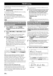
... panel display lights up to 40 stations. To adjust it to how you enter a frequency that the entered frequency is effective when the tuner can receive strong signals without any interference. When you keep holding the key, the search continues even when a station is out of... of FM/AM stations by registering them to specific numbers, and later just select those numbers to better quality sound even when the tuner cannot receive a strong signal. The TUNED indicator on the front panel display according to the band that is tuned in to specify the frequency. When you have selected...
... panel display lights up to 40 stations. To adjust it to how you enter a frequency that the entered frequency is effective when the tuner can receive strong signals without any interference. When you keep holding the key, the search continues even when a station is out of... of FM/AM stations by registering them to specific numbers, and later just select those numbers to better quality sound even when the tuner cannot receive a strong signal. The TUNED indicator on the front panel display according to the band that is tuned in to specify the frequency. When you have selected...

Owner's Manual
Page 33
... registered to the selected preset number is currently registered to the preset number) y • You can manually register AM stations or FM stations with weak signals. 1 Tune in to a station referring to "Tuning in Memory" is displayed it means that is cleared. New registered frequency 01:Empty Preset number Flashing Empty...
... registered to the selected preset number is currently registered to the preset number) y • You can manually register AM stations or FM stations with weak signals. 1 Tune in to a station referring to "Tuning in Memory" is displayed it means that is cleared. New registered frequency 01:Empty Preset number Flashing Empty...

Owner's Manual
Page 37
The OPTION menu appears. Input Source Menu item HDMI1-4 Volume Trim Decoder Mode EXTD Signal Info Surround Volume Trim AV1-4 Volume Trim Decoder Mode EXTD Signal Info Surround 3 Select the desired menu item using gInput selection keys. y • When nCursor or other keys do not work after completing the menu, select ...
The OPTION menu appears. Input Source Menu item HDMI1-4 Volume Trim Decoder Mode EXTD Signal Info Surround Volume Trim AV1-4 Volume Trim Decoder Mode EXTD Signal Info Surround 3 Select the desired menu item using gInput selection keys. y • When nCursor or other keys do not work after completing the menu, select ...

