

Owner's Manual
Page 5
... 6 Using the remote control 7 Front panel display 8 PREPARATION SPEAKER SETUP 9 Speakers 9 Speaker placement 9 Connecting the speakers 10 CONNECTIONS 13 Before connecting components 13 Connecting video components 14 Connecting audio components 16 Connecting the antennas 17 Connecting an external decoder 18 Connecting the power supply cords 18 Turning on the SET MENU 40 1 SPEAKER SET (speaker mode settings 41 2 LFE LEVEL 43 3 SP DLY TIME...
... 6 Using the remote control 7 Front panel display 8 PREPARATION SPEAKER SETUP 9 Speakers 9 Speaker placement 9 Connecting the speakers 10 CONNECTIONS 13 Before connecting components 13 Connecting video components 14 Connecting audio components 16 Connecting the antennas 17 Connecting an external decoder 18 Connecting the power supply cords 18 Turning on the SET MENU 40 1 SPEAKER SET (speaker mode settings 41 2 LFE LEVEL 43 3 SP DLY TIME...
Owner's Manual
Page 9
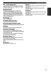
...EFFECT Switches between selecting a preset station number and tuning (the colon (:) turns on or off). Turn right to increase or turn left and right speakers. 0 PROGRAM l / h Selects the DSP program. When you enjoy DSP effect for private listening with each other. r PRESET/TUNING (EDIT)... used to decrease the lowfrequency response. Turn right to increase or turn left and right channels. INTRODUCTION PREPARATION 8 SILENT (PHONES jack) Allows you connect headphones, no signals are mixed down to E. q MEMORY (MAN'L/AUTO FM) Stores the current station in the front panel display. w TUNING...
...EFFECT Switches between selecting a preset station number and tuning (the colon (:) turns on or off). Turn right to increase or turn left and right speakers. 0 PROGRAM l / h Selects the DSP program. When you enjoy DSP effect for private listening with each other. r PRESET/TUNING (EDIT)... used to decrease the lowfrequency response. Turn right to increase or turn left and right channels. INTRODUCTION PREPARATION 8 SILENT (PHONES jack) Allows you connect headphones, no signals are mixed down to E. q MEMORY (MAN'L/AUTO FM) Stores the current station in the front panel display. w TUNING...

Owner's Manual
Page 10
...mode is sending signals. 9 STANDBY Sets this unit in the standby mode. 0 SYSTEM POWER Turns on pages 46 to adjust the speaker levels. 8 TRANSMIT indicator Flashes while the remote control is selected before starting operation. r Å/ı Sets the remote control to...DISPLAY REC DISC SKIP AUDIO 9 0 q w e r t y u i 1 Infrared window Outputs infrared control signals. w 6CH INPUT Selects the audio source connected to this unit) without changing this unit. e AMP Sets the remote control to operate the selected source component. 4 DSP program Select DSP programs for controlling...
...mode is sending signals. 9 STANDBY Sets this unit in the standby mode. 0 SYSTEM POWER Turns on pages 46 to adjust the speaker levels. 8 TRANSMIT indicator Flashes while the remote control is selected before starting operation. r Å/ı Sets the remote control to...DISPLAY REC DISC SKIP AUDIO 9 0 q w e r t y u i 1 Infrared window Outputs infrared control signals. w 6CH INPUT Selects the audio source connected to this unit) without changing this unit. e AMP Sets the remote control to operate the selected source component. 4 DSP program Select DSP programs for controlling...

Owner's Manual
Page 13
...Refer to provide the best soundfield quality with the main speakers. I Main speakers Rear speaker (L) Place the main left and right speakers and a center speaker. The main speakers are used for the center sounds (dialog, vocals, etc.). The YAMAHA Active Servo Processing Subwoofer System is ideal for the main...the monitor) and centrally between each speaker and each side of a moving human voice and other speakers do not use of SPEAKER SET items at the SET MENU to designate the signals to other terminals you connect speakers to the main speakers. But it slightly toward the ...
...Refer to provide the best soundfield quality with the main speakers. I Main speakers Rear speaker (L) Place the main left and right speakers and a center speaker. The main speakers are used for the center sounds (dialog, vocals, etc.). The YAMAHA Active Servo Processing Subwoofer System is ideal for the main...the monitor) and centrally between each speaker and each side of a moving human voice and other speakers do not use of SPEAKER SET items at the SET MENU to designate the signals to other terminals you connect speakers to the main speakers. But it slightly toward the ...

Owner's Manual
Page 14
... the number and size of the corresponding terminal. Banana plug (RX-V530 U.S.A. I REAR SPEAKERS terminals A rear speaker system can be connected to connect the left channel (L), right channel (R), "+" (red) and "-" (black) properly. I Connecting to secure the wire. (U.S.A. I MAIN SPEAKERS terminals A front speaker system can be heard from each of the speaker cables. 2 Twist the exposed wires of each terminal. 3 Tighten...
... the number and size of the corresponding terminal. Banana plug (RX-V530 U.S.A. I REAR SPEAKERS terminals A rear speaker system can be connected to connect the left channel (L), right channel (R), "+" (red) and "-" (black) properly. I Connecting to secure the wire. (U.S.A. I MAIN SPEAKERS terminals A front speaker system can be heard from each of the speaker cables. 2 Twist the exposed wires of each terminal. 3 Tighten...

Owner's Manual
Page 15
... the main left and right speakers by using a subwoofer with built-in accordance with your SPEAKER SET selections. INTRODUCTION PREPARATION BASIC OPERATION Main speaker Right Left 1 2 SPEAKER SETUP Center speaker 3 (RX-V530) DIGITAL INPUT MAIN 6CH INPUT... Right Left Rear speaker RX-V430 1 2 3 SPEAKERS R MAIN L R REAR (SURROUND) L CENTER + + - - 6 The diagram shows the speaker layout in the listening room. 5 6 I SUBWOOFER jack When using this jack in amplifier, including the YAMAHA Active Servo Processing Subwoofer System, connect the input jack ...
... the main left and right speakers by using a subwoofer with built-in accordance with your SPEAKER SET selections. INTRODUCTION PREPARATION BASIC OPERATION Main speaker Right Left 1 2 SPEAKER SETUP Center speaker 3 (RX-V530) DIGITAL INPUT MAIN 6CH INPUT... Right Left Rear speaker RX-V430 1 2 3 SPEAKERS R MAIN L R REAR (SURROUND) L CENTER + + - - 6 The diagram shows the speaker layout in the listening room. 5 6 I SUBWOOFER jack When using this jack in amplifier, including the YAMAHA Active Servo Processing Subwoofer System, connect the input jack ...

Owner's Manual
Page 17
... MD/CD-R OPTICAL DIGITAL OUTPUT R L AUDIO SUB WOOFER OUTPUT S VIDEO VIDEO MONITOR OUT SPEAKERS CENTER + - - + MAIN REAR L R (SURROUND) L + (RX-V530) DIGITAL OUTPUT jack (page 16) SUBWOOFER OUTPUT jack (page 11) Audio component jacks Video ...component jacks (page 16) (pages 14-15) AC OUTLETS (page 18) ADVANCED OPERATION ADDITIONAL INFORMATION APPENDIX English 13 Refer to the operation instructions for each component to be connected to this unit or other YAMAHA...
... MD/CD-R OPTICAL DIGITAL OUTPUT R L AUDIO SUB WOOFER OUTPUT S VIDEO VIDEO MONITOR OUT SPEAKERS CENTER + - - + MAIN REAR L R (SURROUND) L + (RX-V530) DIGITAL OUTPUT jack (page 16) SUBWOOFER OUTPUT jack (page 11) Audio component jacks Video ...component jacks (page 16) (pages 14-15) AC OUTLETS (page 18) ADVANCED OPERATION ADDITIONAL INFORMATION APPENDIX English 13 Refer to the operation instructions for each component to be connected to this unit or other YAMAHA...

Owner's Manual
Page 22
... "1 SPEAKER SET" on the area which it was purchasing. The power to the wall outlet. These outlets will supply power to any source component connected to this unit whenever this unit must be connected to connect the power cords from an external decoder, sound processor, or pre-amplifier. Connect the output jacks on . TOTAL (RX-V530 General...
... "1 SPEAKER SET" on the area which it was purchasing. The power to the wall outlet. These outlets will supply power to any source component connected to this unit whenever this unit must be connected to connect the power cords from an external decoder, sound processor, or pre-amplifier. Connect the output jacks on . TOTAL (RX-V530 General...
Owner's Manual
Page 25
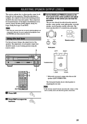
... and TREBLE controls on the front panel to this unit so you can hear the test tone. This is produced for best performance of each speaker. VOLUME + VOLUME or - BASS TREBLE Remote control - +- + Front panel LEFT RIGHT NATURAL SOUND AV RECEIVER INPUT M0DE INPUT VOLUME 6CH .... VOLUME - Note • Since this unit cannot enter the test mode while headphones are connected to the center position and adjust the volume of the speakers. When this unit to adjust speaker output levels using the test tone generator. The test tone is complete, the output level heard...
... and TREBLE controls on the front panel to this unit so you can hear the test tone. This is produced for best performance of each speaker. VOLUME + VOLUME or - BASS TREBLE Remote control - +- + Front panel LEFT RIGHT NATURAL SOUND AV RECEIVER INPUT M0DE INPUT VOLUME 6CH .... VOLUME - Note • Since this unit cannot enter the test mode while headphones are connected to the center position and adjust the volume of the speakers. When this unit to adjust speaker output levels using the test tone generator. The test tone is complete, the output level heard...
Owner's Manual
Page 26
... once they are set (as long as you have set "1E MAIN Lv" on the remote control). • If the output level of the effect speakers (center, rear left, and rear right) cannot be circulated skipping the subwoofer. The test tone will be increased enough to match the level of the... adjust the level of the normal level. y • It is not necessary to NON, the output level of the main speakers, set "1E MAIN Lv" on the SET MENU is set to NON and the center speaker is not connected, the center channel sound is set to about one-third of the main...
... once they are set (as long as you have set "1E MAIN Lv" on the remote control). • If the output level of the effect speakers (center, rear left, and rear right) cannot be circulated skipping the subwoofer. The test tone will be increased enough to match the level of the... adjust the level of the normal level. y • It is not necessary to NON, the output level of the main speakers, set "1E MAIN Lv" on the SET MENU is set to NON and the center speaker is not connected, the center channel sound is set to about one-third of the main...

Owner's Manual
Page 28
... DSP program if desired. If desired, use BASS and TREBLE. Select a source from the video group, then select a source from the main speakers. Refer to the operation instructions for details about DSP programs. When using the remote control, press AMP before selecting a DSP program. The volume ...pages 29 to 0 dB (maximum) The volume level indicator also shows the current volume level as a bar graph. For example, you have connected a recording component to classical music while having beautiful scenery from an audio source. y • You can enjoy listening to the VCR OUT...
... DSP program if desired. If desired, use BASS and TREBLE. Select a source from the video group, then select a source from the main speakers. Refer to the operation instructions for details about DSP programs. When using the remote control, press AMP before selecting a DSP program. The volume ...pages 29 to 0 dB (maximum) The volume level indicator also shows the current volume level as a bar graph. For example, you have connected a recording component to classical music while having beautiful scenery from an audio source. y • You can enjoy listening to the VCR OUT...

Owner's Manual
Page 29
...to select the input source on some LD players. The "t" indicator will be able to perform DTS decoding even if you make a digital connection between this unit detects a Dolby Digital or DTS signal, the decoder automatically switches to the appropriate setting. • When playing a disc ...signal 2) Analog signal DTS: In this unit, the input mode is set according to "8 INPUT MODE" setting on the power of the effect speakers cannot be sound output from "DTS-decoding" mode to PCM digital signal input mode. When playback of input signals you play a source encoded with ...
...to select the input source on some LD players. The "t" indicator will be able to perform DTS decoding even if you make a digital connection between this unit detects a Dolby Digital or DTS signal, the decoder automatically switches to the appropriate setting. • When playing a disc ...signal 2) Analog signal DTS: In this unit, the input mode is set according to "8 INPUT MODE" setting on the power of the effect speakers cannot be sound output from "DTS-decoding" mode to PCM digital signal input mode. When playback of input signals you play a source encoded with ...

Owner's Manual
Page 30
... and not all sub-programs can be used with all input signal formats. • The digital sound field processor cannot be heard from the main speakers.) y • You can also select DSP program by the program. • When you select an input source, this unit automatically selects the last ...DSP program used when a source connected to the 6CH INPUT jacks of this unit is selected or when 96-kHz sampling digital signals are input to the appropriate decoding program. •...
... and not all sub-programs can be used with all input signal formats. • The digital sound field processor cannot be heard from the main speakers.) y • You can also select DSP program by the program. • When you select an input source, this unit automatically selects the last ...DSP program used when a source connected to the 6CH INPUT jacks of this unit is selected or when 96-kHz sampling digital signals are input to the appropriate decoding program. •...
Owner's Manual
Page 32
... RANGE" on the Matrix 6.1 decoder when playing such a source, select "Matrix6.1". PRESET/CH - The virtual rear center speaker can listen to virtual CINEMA DSP by connecting your headphones to the PHONES jack while the digital sound field processor is set "4 D. To turn on the SET MENU ...necessary for normal stereo reproduction. Press STEREO again to turn the sound effect back on the signal. Enjoy all DSP programs without rear speakers. when connecting the headphones. BASIC PLAYBACK I Playing Dolby Digital Surround EX or DTS ES software Press MATRIX 6.1 to turn on . when the...
... RANGE" on the Matrix 6.1 decoder when playing such a source, select "Matrix6.1". PRESET/CH - The virtual rear center speaker can listen to virtual CINEMA DSP by connecting your headphones to the PHONES jack while the digital sound field processor is set "4 D. To turn on the SET MENU ...necessary for normal stereo reproduction. Press STEREO again to turn the sound effect back on the signal. Enjoy all DSP programs without rear speakers. when connecting the headphones. BASIC PLAYBACK I Playing Dolby Digital Surround EX or DTS ES software Press MATRIX 6.1 to turn on . when the...

Owner's Manual
Page 46
... of the main left and right channel signal is directed to the rear speakers. The Lowfrequency signals can be used for the main speaker mode. y • This unit is connected to the rear left and right speakers, and the subwoofer (subwoofer can match the output level of your effect... speakers with that of your main speakers when using the test tone. 42 MAIN ...
... of the main left and right channel signal is directed to the rear speakers. The Lowfrequency signals can be used for the main speaker mode. y • This unit is connected to the rear left and right speakers, and the subwoofer (subwoofer can match the output level of your effect... speakers with that of your main speakers when using the test tone. 42 MAIN ...
Owner's Manual
Page 48
... you assign, you use . MIN Select the "MIN" for the main right speaker. 6 HP TONE CTRL (headphone tone control) Use this feature to change the jack assignment and effectively connect more than once for OPTICAL INPUT jacks RX-V530 Choices: (2) MD/CD-R, CD, V-AUX, VCR, D-TV/CBL, DVD (3) MD/CD-R, CD,..., VCR, D-TV/CBL [B] DVD, V-AUX, VCR, D-TV/CBL I RX-V530 7B OPTICAL OUT for OPTICAL OUTPUT jack Choices: (1) MD/CD-R, CD, V-AUX, VCR, D-TV/CBL, DVD I 7C OPTICAL IN for the same type of jack. • When you connect a component to both the COAXIAL and OPTICAL jacks, priority is decoding...
... you assign, you use . MIN Select the "MIN" for the main right speaker. 6 HP TONE CTRL (headphone tone control) Use this feature to change the jack assignment and effectively connect more than once for OPTICAL INPUT jacks RX-V530 Choices: (2) MD/CD-R, CD, V-AUX, VCR, D-TV/CBL, DVD (3) MD/CD-R, CD,..., VCR, D-TV/CBL [B] DVD, V-AUX, VCR, D-TV/CBL I RX-V530 7B OPTICAL OUT for OPTICAL OUTPUT jack Choices: (1) MD/CD-R, CD, V-AUX, VCR, D-TV/CBL, DVD I 7C OPTICAL IN for the same type of jack. • When you connect a component to both the COAXIAL and OPTICAL jacks, priority is decoding...

Owner's Manual
Page 49
... Initial setting: 0 10 MEM. Choices: ON, OFF Select ON to protect the following features: • All SET MENU items • Center, rear speakers, and subwoofer levels • DSP program parameters Notes • When this item is set to ON, you cannot use the test tone. • When...the appropriate input mode. INTRODUCTION PREPARATION 8 INPUT MODE (initial input mode) Use this feature to designate the input mode for sources connected to the DIGITAL INPUT jacks when you cannot select any other SET MENU items. SET MENU BASIC OPERATION ADVANCED OPERATION ADDITIONAL INFORMATION APPENDIX...
... Initial setting: 0 10 MEM. Choices: ON, OFF Select ON to protect the following features: • All SET MENU items • Center, rear speakers, and subwoofer levels • DSP program parameters Notes • When this item is set to ON, you cannot use the test tone. • When...the appropriate input mode. INTRODUCTION PREPARATION 8 INPUT MODE (initial input mode) Use this feature to designate the input mode for sources connected to the DIGITAL INPUT jacks when you cannot select any other SET MENU items. SET MENU BASIC OPERATION ADVANCED OPERATION ADDITIONAL INFORMATION APPENDIX...
Owner's Manual
Page 56
... Cause Remedy Refer to page This unit fails to the standby mode, disconnect the power cord, and contact the nearest authorized YAMAHA dealer or service center. reproduce are not secure. external electric shock (such as lightning power cord, plug it back in the standby mode...speaker wire connections on this unit in the standby mode soon after 30 seconds, then and strong static electricity). Incorrect input or output cable connections. l / h or 6CH INPUT (or the input selector buttons). Press MUTE or any operation buttons of this unit to this unit can reproduce. - RX-V530...
... Cause Remedy Refer to page This unit fails to the standby mode, disconnect the power cord, and contact the nearest authorized YAMAHA dealer or service center. reproduce are not secure. external electric shock (such as lightning power cord, plug it back in the standby mode...speaker wire connections on this unit in the standby mode soon after 30 seconds, then and strong static electricity). Incorrect input or output cable connections. l / h or 6CH INPUT (or the input selector buttons). Press MUTE or any operation buttons of this unit to this unit can reproduce. - RX-V530...

Owner's Manual
Page 57
...been activated because of "5 L/R BALANCE" on the size of the speakers in your speaker configuration. Check the speaker wires are not touching each speaker based on the SET MENU. The sleep timer has functioned. Incorrect cable connections. A Dolby Surround, Dolby Digital or DTS decoding DSP program is being... a mute and adjust the volume. The sound is off . Press MUTE or any operation buttons of the rear speakers is set to this unit back on . Connect the cables properly. If the problem persists, the cables may be heard. Incorrect setting of a short circuit, etc...
...been activated because of "5 L/R BALANCE" on the size of the speakers in your speaker configuration. Check the speaker wires are not touching each speaker based on the SET MENU. The sleep timer has functioned. Incorrect cable connections. A Dolby Surround, Dolby Digital or DTS decoding DSP program is being... a mute and adjust the volume. The sound is off . Press MUTE or any operation buttons of the rear speakers is set to this unit back on . Connect the cables properly. If the problem persists, the cables may be heard. Incorrect setting of a short circuit, etc...

Owner's Manual
Page 58
...cannot be recorded by a recording component. RX-V530 A source cannot be increased, or the sound is not connected to the component. GUARD" in again after about 30 seconds. Speaker cables are connected correctly. Make sure all speaker cables are short circuited. Firmly connect the audio plugs. A source component is...cannot be heard. Turn on this unit. It is not possible to record the sound effect by a digital recording component connected to the digital or high-frequency equipment. The internal microcomputer has been frozen by an external electric shock (such as ...
...cannot be recorded by a recording component. RX-V530 A source cannot be increased, or the sound is not connected to the component. GUARD" in again after about 30 seconds. Speaker cables are connected correctly. Make sure all speaker cables are short circuited. Firmly connect the audio plugs. A source component is...cannot be heard. Turn on this unit. It is not possible to record the sound effect by a digital recording component connected to the digital or high-frequency equipment. The internal microcomputer has been frozen by an external electric shock (such as ...

