

Owner's Manual
Page 2
... tub; If you to be adhered to qualified service personnel. 19 Damage Requiring Service - Do not defeat the safety purpose of power supply to ensure reliable operation of any kind into this product from the type of important operating and maintenance (servicing) instructions in ... and use liquid cleaners or aerosol cleaners. Any mounting of Graphical Symbols The lightning flash with them , paying particular attention to . 11 Power Sources - SAFETY INSTRUCTIONS CAUTION RISK OF ELECTRIC SHOCK DO NOT OPEN CAUTION: TO REDUCE THE RISK OF ELECTRIC SHOCK, DO NOT REMOVE COVER...
... tub; If you to be adhered to qualified service personnel. 19 Damage Requiring Service - Do not defeat the safety purpose of power supply to ensure reliable operation of any kind into this product from the type of important operating and maintenance (servicing) instructions in ... and use liquid cleaners or aerosol cleaners. Any mounting of Graphical Symbols The lightning flash with them , paying particular attention to . 11 Power Sources - SAFETY INSTRUCTIONS CAUTION RISK OF ELECTRIC SHOCK DO NOT OPEN CAUTION: TO REDUCE THE RISK OF ELECTRIC SHOCK, DO NOT REMOVE COVER...

Owner's Manual
Page 3
... that provides guidelines for the grounding electrode. This equipment generates/uses radio frequencies and, if not installed and used replacement parts specified by Yamaha Corporation of any way, and f) When the product exhibits a distinct change the lead-in to use the product. 2. If this...- NATIONAL ELECTRICAL CODE ANTENNA LEAD IN WIRE ANTENNA DISCHARGE UNIT (NEC SECTION 810-20) GROUNDING CONDUCTORS (NEC SECTION 810-21) GROUND CLAMPS POWER SERVICE GROUNDING ELECTRODE SYSTEM (NEC ART 250. PART H) FCC INFORMATION (for service. 20 Replacement Parts - IMPORTANT NOTICE : DO NOT MODIFY ...
... that provides guidelines for the grounding electrode. This equipment generates/uses radio frequencies and, if not installed and used replacement parts specified by Yamaha Corporation of any way, and f) When the product exhibits a distinct change the lead-in to use the product. 2. If this...- NATIONAL ELECTRICAL CODE ANTENNA LEAD IN WIRE ANTENNA DISCHARGE UNIT (NEC SECTION 810-20) GROUNDING CONDUCTORS (NEC SECTION 810-21) GROUND CLAMPS POWER SERVICE GROUNDING ELECTRODE SYSTEM (NEC ART 250. PART H) FCC INFORMATION (for service. 20 Replacement Parts - IMPORTANT NOTICE : DO NOT MODIFY ...

Owner's Manual
Page 4
...avoid prolonged exposure from use of time (i.e. this unit is called the standby mode. Contact qualified YAMAHA service personnel when any damage resulting from excessive volume levels. vacation), disconnect the AC power plug from the wall outlet, grasp the plug; MODEL: Serial No.: The serial number is ...unit is turned off. Using this unit, and/or personal injury. YAMAHA will not be opened for future reference. 2 Install this unit in the standby mode, and disconnect the AC power plug from the AC power source as long as they may get the most importantly, without ...
...avoid prolonged exposure from use of time (i.e. this unit is called the standby mode. Contact qualified YAMAHA service personnel when any damage resulting from excessive volume levels. vacation), disconnect the AC power plug from the wall outlet, grasp the plug; MODEL: Serial No.: The serial number is ...unit is turned off. Using this unit, and/or personal injury. YAMAHA will not be opened for future reference. 2 Install this unit in the standby mode, and disconnect the AC power plug from the AC power source as long as they may get the most importantly, without ...

Owner's Manual
Page 5
... 38 Setting the sleep timer 38 Canceling the sleep timer 38 RECORDING 39 ADVANCED OPERATION SET MENU 40 Adjusting the items on the power 19 SPEAKER MODE SETTINGS 20 ADJUSTING SPEAKER OUTPUT LEVELS .. 21 Using the test tone 21 BASIC OPERATION BASIC PLAYBACK 23 Input modes ... CONNECTIONS 13 Before connecting components 13 Connecting video components 14 Connecting audio components 16 Connecting the antennas 17 Connecting an external decoder 18 Connecting the power supply cords 18 Turning on the SET MENU 40 1 SPEAKER SET (speaker mode settings 41 2 LFE LEVEL 43 3 SP DLY TIME ...
... 38 Setting the sleep timer 38 Canceling the sleep timer 38 RECORDING 39 ADVANCED OPERATION SET MENU 40 Adjusting the items on the power 19 SPEAKER MODE SETTINGS 20 ADJUSTING SPEAKER OUTPUT LEVELS .. 21 Using the test tone 21 BASIC OPERATION BASIC PLAYBACK 23 Input modes ... CONNECTIONS 13 Before connecting components 13 Connecting video components 14 Connecting audio components 16 Connecting the antennas 17 Connecting an external decoder 18 Connecting the power supply cords 18 Turning on the SET MENU 40 1 SPEAKER SET (speaker mode settings 41 2 LFE LEVEL 43 3 SP DLY TIME ...

Owner's Manual
Page 6
...model name. • y indicates a tip for your Audio/Video system N Test tone generator for both the RX-V530 and RX-V430. In this manual • This document is given in parentheses in operativity ability, and others. "Dolby...Theater Systems, Inc. 2 For details on various functions unique to change in part for the reason of YAMAHA DSP technology and Dolby Pro Logic, Dolby Digital or DTS N Virtual CINEMA DSP N SILENT CINEMA DSP ... remote control. FEATURES Built-in 5-channel power amplifier N Minimum RMS output power (0.06% THD, 20 Hz - 20 kHz, 8Ω) [U.S.A.
...model name. • y indicates a tip for your Audio/Video system N Test tone generator for both the RX-V530 and RX-V430. In this manual • This document is given in parentheses in operativity ability, and others. "Dolby...Theater Systems, Inc. 2 For details on various functions unique to change in part for the reason of YAMAHA DSP technology and Dolby Pro Logic, Dolby Digital or DTS N Virtual CINEMA DSP N SILENT CINEMA DSP ... remote control. FEATURES Built-in 5-channel power amplifier N Minimum RMS output power (0.06% THD, 20 Hz - 20 kHz, 8Ω) [U.S.A.

Owner's Manual
Page 7
... cover. 2 Insert the four supplied batteries (AAA, R03, UM-4) according to make sure it contains the following items. Remote control CODE SET TRANSMIT POWER TV POWER AV STANDBY SYSTEM POWER CD MD/CD-R TUNER SLEEP DVD D-TV/CBL V-AUX 6CH INPUT VCR A B AMP Batteries (4) (AAA, R03, UM-4) ++ + TV VOL TV CH -- When the...
... cover. 2 Insert the four supplied batteries (AAA, R03, UM-4) according to make sure it contains the following items. Remote control CODE SET TRANSMIT POWER TV POWER AV STANDBY SYSTEM POWER CD MD/CD-R TUNER SLEEP DVD D-TV/CBL V-AUX 6CH INPUT VCR A B AMP Batteries (4) (AAA, R03, UM-4) ++ + TV VOL TV CH -- When the...
Owner's Manual
Page 8
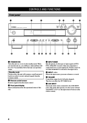
... when one component is selected as the input source. 5 INPUT l / h Selects the input source you will hear a click and there will consume a small amount of power in order to receive infrared-signals from the remote control. 2 Remote control sensor Receives signals from the remote control. 3 Front panel display Shows information about...
... when one component is selected as the input source. 5 INPUT l / h Selects the input source you will hear a click and there will consume a small amount of power in order to receive infrared-signals from the remote control. 2 Remote control sensor Receives signals from the remote control. 3 Front panel display Shows information about...

Owner's Manual
Page 10
...a button repeatedly to select a DSP program within that the AMP mode is sending signals. 9 STANDBY Sets this unit in the standby mode. 0 SYSTEM POWER Turns on pages 46 to the AMP mode for the AMP position. e AMP Sets the remote control to 48. 1 8 2 3 4 5 6 7 CODE SET ... MD/CD-R TUNER SLEEP DVD D-TV/CBL V-AUX 6CH INPUT VCR A B AMP ++ + TV VOL TV CH -- See "REMOTE CONTROL FEATURES" on the power of this unit. TV MUTE TV INPUT MUTE HALL 1 JAZZ CLUB 2 ROCK CONCERT 3 ENTERTAINMENT 4 TV SPORTS 5 MONO MOVIE 6 MOVIE MOVIE THEATER 1 THEATER 2 7 8 /DTS ...
...a button repeatedly to select a DSP program within that the AMP mode is sending signals. 9 STANDBY Sets this unit in the standby mode. 0 SYSTEM POWER Turns on pages 46 to the AMP mode for the AMP position. e AMP Sets the remote control to 48. 1 8 2 3 4 5 6 7 CODE SET ... MD/CD-R TUNER SLEEP DVD D-TV/CBL V-AUX 6CH INPUT VCR A B AMP ++ + TV VOL TV CH -- See "REMOTE CONTROL FEATURES" on the power of this unit. TV MUTE TV INPUT MUTE HALL 1 JAZZ CLUB 2 ROCK CONCERT 3 ENTERTAINMENT 4 TV SPORTS 5 MONO MOVIE 6 MOVIE MOVIE THEATER 1 THEATER 2 7 8 /DTS ...

Owner's Manual
Page 13
...smoothly. The main speakers should also be high-performance models and have to be the speakers from the ideal listening position. The YAMAHA Active Servo Processing Subwoofer System is effective not only for effect and surround sounds. Speaker placement Refer to . I Center speaker ... of equivalent performance with high fidelity when playing back Dolby Digital or DTS signals. We recommend that you do not have enough power-handling capacity to reduce wall reflections. The distance between the main speakers. Note • If you use different brands of speakers...
...smoothly. The main speakers should also be high-performance models and have to be the speakers from the ideal listening position. The YAMAHA Active Servo Processing Subwoofer System is effective not only for effect and surround sounds. Speaker placement Refer to . I Center speaker ... of equivalent performance with high fidelity when playing back Dolby Digital or DTS signals. We recommend that you do not have enough power-handling capacity to reduce wall reflections. The distance between the main speakers. Note • If you use different brands of speakers...

Owner's Manual
Page 15
... BASIC OPERATION Main speaker Right Left 1 2 SPEAKER SETUP Center speaker 3 (RX-V530) DIGITAL INPUT MAIN 6CH INPUT CD SURROUND COAXIAL OPTICAL D-TV/CBL SUB WOOFER...MAIN : 8ΩMIN. /SPEAKER CENTER : 8ΩMIN. /SPEAKER REAR : 8ΩMIN. /SPEAKER SET BEFORE POWER ON IMPEDANCE SELECTOR MAIN CENTER REAR : 4ΩMIN. /SPEAKER : 6ΩMIN. /SPEAKER : 6ΩMIN. /...Right Left Rear speaker RX-V430 1 2 3 SPEAKERS R MAIN L R REAR (SURROUND) L CENTER + + - - 6 The diagram shows the speaker layout in amplifier, including the YAMAHA Active Servo Processing ...
... BASIC OPERATION Main speaker Right Left 1 2 SPEAKER SETUP Center speaker 3 (RX-V530) DIGITAL INPUT MAIN 6CH INPUT CD SURROUND COAXIAL OPTICAL D-TV/CBL SUB WOOFER...MAIN : 8ΩMIN. /SPEAKER CENTER : 8ΩMIN. /SPEAKER REAR : 8ΩMIN. /SPEAKER SET BEFORE POWER ON IMPEDANCE SELECTOR MAIN CENTER REAR : 4ΩMIN. /SPEAKER : 6ΩMIN. /SPEAKER : 6ΩMIN. /...Right Left Rear speaker RX-V430 1 2 3 SPEAKERS R MAIN L R REAR (SURROUND) L CENTER + + - - 6 The diagram shows the speaker layout in amplifier, including the YAMAHA Active Servo Processing ...

Owner's Manual
Page 16
... + - - - + + REAR R MAIN L R (SURROUND) L MAIN : 8ΩMIN. /SPEAKER CENTER : 8ΩMIN. /SPEAKER REAR : 8ΩMIN. /SPEAKER SET BEFORE POWER ON IMPEDANCE SELECTOR MAIN CENTER REAR : 4ΩMIN. /SPEAKER : 6ΩMIN. /SPEAKER : 6ΩMIN. /SPEAKER (RX-V530 U.S.A. Main The impedance of each speaker must be 6 Ω or higher. Select the switch position (left or right...
... + - - - + + REAR R MAIN L R (SURROUND) L MAIN : 8ΩMIN. /SPEAKER CENTER : 8ΩMIN. /SPEAKER REAR : 8ΩMIN. /SPEAKER SET BEFORE POWER ON IMPEDANCE SELECTOR MAIN CENTER REAR : 4ΩMIN. /SPEAKER : 6ΩMIN. /SPEAKER : 6ΩMIN. /SPEAKER (RX-V530 U.S.A. Main The impedance of each speaker must be 6 Ω or higher. Select the switch position (left or right...

Owner's Manual
Page 17
...-R OPTICAL DIGITAL OUTPUT R L AUDIO SUB WOOFER OUTPUT S VIDEO VIDEO MONITOR OUT SPEAKERS CENTER + - - + MAIN REAR L R (SURROUND) L + (RX-V530) DIGITAL OUTPUT jack (page 16) SUBWOOFER OUTPUT jack (page 11) Audio component jacks Video component jacks (page 16) (pages 14-15) AC OUTLETS (page 18...) Antenna input terminals (page 17) SPEAKERS terminals (pages 10-11) - YAMAHA applies this labeling system to all its products. • After you connect other components to the mains power until all connections between the components have been completed. • Be sure ...
...-R OPTICAL DIGITAL OUTPUT R L AUDIO SUB WOOFER OUTPUT S VIDEO VIDEO MONITOR OUT SPEAKERS CENTER + - - + MAIN REAR L R (SURROUND) L + (RX-V530) DIGITAL OUTPUT jack (page 16) SUBWOOFER OUTPUT jack (page 11) Audio component jacks Video component jacks (page 16) (pages 14-15) AC OUTLETS (page 18...) Antenna input terminals (page 17) SPEAKERS terminals (pages 10-11) - YAMAHA applies this labeling system to all its products. • After you connect other components to the mains power until all connections between the components have been completed. • Be sure ...

Owner's Manual
Page 18
... jacks on while using S-video (or Component video) jacks, you connect this unit with audio signals input from other components. • RX-V530 S-video and component video signals pass independently through this unit for the component being connected. Signals input through the corresponding composite video, S-video...on your video component to the AUDIO OUT jacks and connect the video signal input jack on this unit's video circuit. If the power is off, this unit may differ depending on this unit. I Connecting a DVD player Connect the optical digital audio signal output jack...
... jacks on while using S-video (or Component video) jacks, you connect this unit with audio signals input from other components. • RX-V530 S-video and component video signals pass independently through this unit for the component being connected. Signals input through the corresponding composite video, S-video...on your video component to the AUDIO OUT jacks and connect the video signal input jack on this unit's video circuit. If the power is off, this unit may differ depending on this unit. I Connecting a DVD player Connect the optical digital audio signal output jack...

Owner's Manual
Page 20
... DIGITAL OUTPUT R L AUDIO SUB WOOFER OUTPUT S VIDEO VIDEO MONITOR OUT (RX-V530) indicates signal direction L indicates left analog cables R indicates right analog cables C indicates coaxial cables O indicates optical cables RX-V430 Connect the input jacks on while using this unit, keep its power turned on your CD recorder or MD recorder to the MD...
... DIGITAL OUTPUT R L AUDIO SUB WOOFER OUTPUT S VIDEO VIDEO MONITOR OUT (RX-V530) indicates signal direction L indicates left analog cables R indicates right analog cables C indicates coaxial cables O indicates optical cables RX-V430 Connect the input jacks on while using this unit, keep its power turned on your CD recorder or MD recorder to the MD...

Owner's Manual
Page 21
... AM antenna is a metal stake driven into the slot. AM loop antenna (included) Indoor FM antenna (included) (RX-V530) EO VIDEO TUNER AM ANT GND DVD 75Ω UNBAL. I Connecting the AM loop antenna 1 Set up the...: 100 kHz/10 kHz Other area: 50 kHz/9 kHz Before setting this switch, disconnect the AC power plug of the 75-ohm coaxial cable and prepare it for the best reception. 75-ohm/300-ohm...antenna may improve the quality. Consult the nearest authorized YAMAHA dealer or service center about the outdoor antennas. ADVANCED OPERATION ADDITIONAL INFORMATION APPENDIX English 17
... AM antenna is a metal stake driven into the slot. AM loop antenna (included) Indoor FM antenna (included) (RX-V530) EO VIDEO TUNER AM ANT GND DVD 75Ω UNBAL. I Connecting the AM loop antenna 1 Set up the...: 100 kHz/10 kHz Other area: 50 kHz/9 kHz Before setting this switch, disconnect the AC power plug of the 75-ohm coaxial cable and prepare it for the best reception. 75-ohm/300-ohm...antenna may improve the quality. Consult the nearest authorized YAMAHA dealer or service center about the outdoor antennas. ADVANCED OPERATION ADDITIONAL INFORMATION APPENDIX English 17

Owner's Manual
Page 22
... VOLTAGE SELECTOR AC OUTLETS SWITCHED 50W MAX. TOTAL (RX-V530 General model) I Connecting the AC power cord Plug in this unit to this unit whenever this unit is turned on the SET MENU do not apply (except for "1E MAIN Lv"). These outlets will supply power to any source component connected to the wall... General models) The VOLTAGE SELECTOR on the area which it was purchasing. Voltages are 110/120/ 220/240 V AC, 50/60 Hz. 18 The maximum power (total power consumption of this unit must be connected to the AC OUTLETS is controlled by this unit's STANDBY/ON (or SYSTEM...
... VOLTAGE SELECTOR AC OUTLETS SWITCHED 50W MAX. TOTAL (RX-V530 General model) I Connecting the AC power cord Plug in this unit to this unit whenever this unit is turned on the SET MENU do not apply (except for "1E MAIN Lv"). These outlets will supply power to any source component connected to the wall... General models) The VOLTAGE SELECTOR on the area which it was purchasing. Voltages are 110/120/ 220/240 V AC, 50/60 Hz. 18 The maximum power (total power consumption of this unit must be connected to the AC OUTLETS is controlled by this unit's STANDBY/ON (or SYSTEM...

Owner's Manual
Page 23
...English 19 TV MUTE TV INPUT MUTE HALL ROCK ENTER- INTRODUCTION PREPARATION Turning on the power When all connections are complete, turn on the power of this unit. VOLUME - STANDBY /ON or SYSTEM POWER Front panel Remote control The level of the main volume, and then the current ...DSP program name appear on the front panel display. 2 Turn on the video monitor connected to turn on the power of this unit. 1 NATURAL SOUND AV RECEIVER INPUT M0DE INPUT VOLUME 6CH INPUT STANDBY /ON SILENT PHONES STEREO EFFECT PROGRAM MEMORY TUNING MODE...
...English 19 TV MUTE TV INPUT MUTE HALL ROCK ENTER- INTRODUCTION PREPARATION Turning on the power When all connections are complete, turn on the power of this unit. VOLUME - STANDBY /ON or SYSTEM POWER Front panel Remote control The level of the main volume, and then the current ...DSP program name appear on the front panel display. 2 Turn on the video monitor connected to turn on the power of this unit. 1 NATURAL SOUND AV RECEIVER INPUT M0DE INPUT VOLUME 6CH INPUT STANDBY /ON SILENT PHONES STEREO EFFECT PROGRAM MEMORY TUNING MODE...
Owner's Manual
Page 27
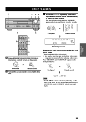
... 5 MONO MOVIE 6 MOVIE MOVIE THEATER 1 THEATER 2 7 8 /DTS SUR. 9 SELECT 0 MATRIX 6.1 STEREO +10 ENTER EFFECT 1 3 5 6 1 Press STANDBY/ON (SYSTEM POWER on the remote control) to turn on the front panel display, no other source can be played. To select another input source, first press 6CH.../AM PRESET/TUNING MAN'L/AUTO FM AUTO/MAN'L MONO EDIT PRESET/TUNING A/B/C/D/E BASS - + TREBLE - + 6 5 3 CODE SET TRANSMIT POWER TV POWER AV STANDBY SYSTEM POWER CD MD/CD-R TUNER SLEEP DVD D-TV/CBL V-AUX 6CH INPUT VCR A B AMP ++ + TV VOL TV CH -- VOLUME -...
... 5 MONO MOVIE 6 MOVIE MOVIE THEATER 1 THEATER 2 7 8 /DTS SUR. 9 SELECT 0 MATRIX 6.1 STEREO +10 ENTER EFFECT 1 3 5 6 1 Press STANDBY/ON (SYSTEM POWER on the remote control) to turn on the front panel display, no other source can be played. To select another input source, first press 6CH.../AM PRESET/TUNING MAN'L/AUTO FM AUTO/MAN'L MONO EDIT PRESET/TUNING A/B/C/D/E BASS - + TREBLE - + 6 5 3 CODE SET TRANSMIT POWER TV POWER AV STANDBY SYSTEM POWER CD MD/CD-R TUNER SLEEP DVD D-TV/CBL V-AUX 6CH INPUT VCR A B AMP ++ + TV VOL TV CH -- VOLUME -...

Owner's Manual
Page 29
... MENU (see page 45 for longer than 30 seconds, this unit will automatically switch from the subwoofer depending on the SPEAKER MODE settings on the power of this unit, the input mode is set the input mode to such a source. If you want to play a source encoded with a DTS signal with...
... MENU (see page 45 for longer than 30 seconds, this unit will automatically switch from the subwoofer depending on the SPEAKER MODE settings on the power of this unit, the input mode is set the input mode to such a source. If you want to play a source encoded with a DTS signal with...

Owner's Manual
Page 30
...MOVIE 6 MOVIE MOVIE THEATER 1 THEATER 2 7 8 /DTS SUR. 9 SELECT 0 MATRIX 6.1 STEREO +10 ENTER EFFECT PROGRAM l / h CODE SET TRANSMIT POWER TV POWER AV STANDBY SYSTEM POWER CD MD/CD-R TUNER SLEEP DVD D-TV/CBL V-AUX 6CH INPUT VCR A B AMP ++ + TV VOL TV CH -- Program names are automatically selected ...when you turn on the power again. • If a Dolby Digital or DTS signal is input when the input mode is set to select the desired program. VOLUME ...
...MOVIE 6 MOVIE MOVIE THEATER 1 THEATER 2 7 8 /DTS SUR. 9 SELECT 0 MATRIX 6.1 STEREO +10 ENTER EFFECT PROGRAM l / h CODE SET TRANSMIT POWER TV POWER AV STANDBY SYSTEM POWER CD MD/CD-R TUNER SLEEP DVD D-TV/CBL V-AUX 6CH INPUT VCR A B AMP ++ + TV VOL TV CH -- Program names are automatically selected ...when you turn on the power again. • If a Dolby Digital or DTS signal is input when the input mode is set to select the desired program. VOLUME ...


