
MCXSP10 Manual
Page 5
... 91 Connecting i.LINK components 91 Basic i.LINK operations 92 Changing i.LINK Select parameters 92 i.LINK display messages 94 USING HDMI 95 What is HDMI 95 Connecting HDMI components 96 Basic HDMI operations 97 Changing HDMI parameters 97 ADDITIONAL INFORMATION EDITING SOUND FIELD PARAMETERS ......99 What is a sound field 99 Changing parameter settings 99 SOUND FIELD...
... 91 Connecting i.LINK components 91 Basic i.LINK operations 92 Changing i.LINK Select parameters 92 i.LINK display messages 94 USING HDMI 95 What is HDMI 95 Connecting HDMI components 96 Basic HDMI operations 97 Changing HDMI parameters 97 ADDITIONAL INFORMATION EDITING SOUND FIELD PARAMETERS ......99 What is a sound field 99 Changing parameter settings 99 SOUND FIELD...
MCXSP10 Manual
Page 6
..., the product has priority. "Dolby", "Surround EX", and the double-D symbol are trademarks or registered trademarks of HDMI Licensing LLC. "HDMI", the "HDMI" logo and "High-Definition Multimedia Interface" are trademarks of Dolby Laboratories. HD Radio™ technology manufactured under license... from SRS Labs, Inc. The THX logo is a trademark of YAMAHA CORPORATION. "i.LINK" and the "i.LINK" logo are ...
..., the product has priority. "Dolby", "Surround EX", and the double-D symbol are trademarks or registered trademarks of HDMI Licensing LLC. "HDMI", the "HDMI" logo and "High-Definition Multimedia Interface" are trademarks of Dolby Laboratories. HD Radio™ technology manufactured under license... from SRS Labs, Inc. The THX logo is a trademark of YAMAHA CORPORATION. "i.LINK" and the "i.LINK" logo are ...

MCXSP10 Manual
Page 9
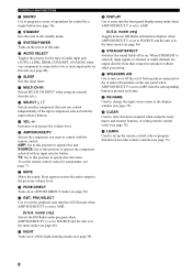
...; In the standby mode, this unit. 8 PRESET/TUNING (EDIT) Switches the function of power in the tuner mode and the colon (:) is in order to receive infrared-signals from the remote control. • You can reproduce sound. Selects the tuning frequency when the unit is in the tuner mode (see page... the tuner mode. 5 When you want to listen to or watch. 3 AUDIO SELECT Toggles the priority for the type of audio input jack (AUTO, i.LINK, HDMI, COAX/OPT, ANALOG) when one of the 5 preset station groups (A to 43).
...; In the standby mode, this unit. 8 PRESET/TUNING (EDIT) Switches the function of power in the tuner mode and the colon (:) is in order to receive infrared-signals from the remote control. • You can reproduce sound. Selects the tuning frequency when the unit is in the tuner mode (see page... the tuner mode. 5 When you want to listen to or watch. 3 AUDIO SELECT Toggles the priority for the type of audio input jack (AUTO, i.LINK, HDMI, COAX/OPT, ANALOG) when one of the 5 preset station groups (A to 43).
MCXSP10 Manual
Page 12
... to change the input source name in the tuner mode (see page 75). D SYSTEM POWER Turns on the power of audio input jack (AUTO, i.LINK, HDMI, COAX/OPT, ANALOG) when one component is set up the remote control code or program functions from their respective speakers without effect processing. F SLEEP Sets...
... to change the input source name in the tuner mode (see page 75). D SYSTEM POWER Turns on the power of audio input jack (AUTO, i.LINK, HDMI, COAX/OPT, ANALOG) when one component is set up the remote control code or program functions from their respective speakers without effect processing. F SLEEP Sets...
MCXSP10 Manual
Page 14
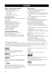
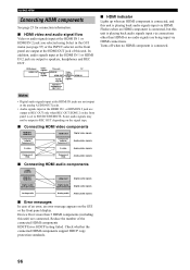
Turns off when no HDMI component is connected. F SLEEP indicator Lights up when this unit is reproducing PCM (pulse code modulation) digital audio signals. E PCM indicator Lights up when a THX program is selected. H THX indicator Lights up when this unit is receiving a stereo signal for an ...FM stereo broadcast while the AUTO indicator is lit. Flashes when an i.LINK component is connected, but this unit is playing back signals input via connections other than HDMI or no audio signals are connected. 10...
Turns off when no HDMI component is connected. F SLEEP indicator Lights up when this unit is reproducing PCM (pulse code modulation) digital audio signals. E PCM indicator Lights up when a THX program is selected. H THX indicator Lights up when this unit is receiving a stereo signal for an ...FM stereo broadcast while the AUTO indicator is lit. Flashes when an i.LINK component is connected, but this unit is playing back signals input via connections other than HDMI or no audio signals are connected. 10...
MCXSP10 Manual
Page 16
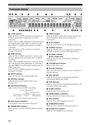
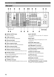
DVD DTV HDMI IN 1 GND AM ANT CBL/SAT DVD COMPONENT VIDEO Y PB PR IN 2 DTV CD DVD CBL/ SAT OUT MONITOR OUT DVR/VCR 2 COAXIAL DIGITAL INPUT ... page 24 for connection information. 4 Video component jacks See pages 19 and 21 for connection information. 5 Audio component jacks See page 22 for connection information. C HDMI IN/OUT connectors See page 95 for details. G Speaker terminals See page 15 for connection information. 6 Speaker terminal wrench hook Use to your other A/V components...
DVD DTV HDMI IN 1 GND AM ANT CBL/SAT DVD COMPONENT VIDEO Y PB PR IN 2 DTV CD DVD CBL/ SAT OUT MONITOR OUT DVR/VCR 2 COAXIAL DIGITAL INPUT ... page 24 for connection information. 4 Video component jacks See pages 19 and 21 for connection information. 5 Audio component jacks See page 22 for connection information. C HDMI IN/OUT connectors See page 95 for details. G Speaker terminals See page 15 for connection information. 6 Speaker terminal wrench hook Use to your other A/V components...
MCXSP10 Manual
Page 27
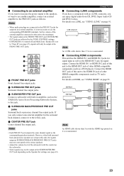
... both surround back and presence speakers are setup in amplifier, such as the YAMAHA Active Servo Processing Subwoofer System, to this unit to the HDMI OUT jack of other HDMI-compatible components (such as TV and a projector). Connect the HDMI IN 1 or HDMI IN 2 jack of this jack. 4 SURROUND BACK/PRESENCE PRE OUT jacks... to an external amplifier, it to the left (L) jack. 5 CENTER PRE OUT jack Center channel line output jack. Connect the HDMI OUT jack of this unit to the HDMI IN jack of the subwoofer with built-in this unit to the maximum. • The signal output at the FRONT PRE OUT...
... both surround back and presence speakers are setup in amplifier, such as the YAMAHA Active Servo Processing Subwoofer System, to this unit to the HDMI OUT jack of other HDMI-compatible components (such as TV and a projector). Connect the HDMI IN 1 or HDMI IN 2 jack of this jack. 4 SURROUND BACK/PRESENCE PRE OUT jacks... to an external amplifier, it to the left (L) jack. 5 CENTER PRE OUT jack Center channel line output jack. Connect the HDMI OUT jack of this unit to the HDMI IN jack of the subwoofer with built-in this unit to the maximum. • The signal output at the FRONT PRE OUT...

MCXSP10 Manual
Page 44
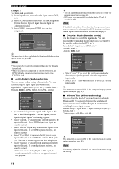
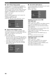
Press AUDIO SELECT to select Audio Info. AUDIO SELECT or POWER TV POWER AV STANDBY SYSTEM POWER A B AUDIO SELECT SLEEP PHONO TUNER CD MULTI CH IN Front panel Remote control ■ Displaying information about the input source You ...automatically switches to analog input. If no analog signals are input, no sound is output. * If this unit selects when the power is output. HDMI Selects only HDMI signals. Format Sampling Channel Bitrate Dialogue Flag1 Flag2 Analog --2/0/----------- Bitrate Bit rate. The top display appears. If no i.LINK signals are input, no ...
Press AUDIO SELECT to select Audio Info. AUDIO SELECT or POWER TV POWER AV STANDBY SYSTEM POWER A B AUDIO SELECT SLEEP PHONO TUNER CD MULTI CH IN Front panel Remote control ■ Displaying information about the input source You ...automatically switches to analog input. If no analog signals are input, no sound is output. * If this unit selects when the power is output. HDMI Selects only HDMI signals. Format Sampling Channel Bitrate Dialogue Flag1 Flag2 Analog --2/0/----------- Bitrate Bit rate. The top display appears. If no i.LINK signals are input, no ...
MCXSP10 Manual
Page 51
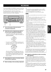
... the analog signal will result in noise being dubbed, the picture itself may infringe copyright laws. • Audio signals input from the selected i.LINK or HDMI components are output to REC OUT when REC OUT/ZONE 2 on the front panel is connected to provide only an S-video (or only a composite video...
... the analog signal will result in noise being dubbed, the picture itself may infringe copyright laws. • Audio signals input from the selected i.LINK or HDMI components are output to REC OUT when REC OUT/ZONE 2 on the front panel is connected to provide only an S-video (or only a composite video...
MCXSP10 Manual
Page 56
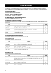
... initial settings (indicated in bold under each speaker. Changes the name of each parameter) to reflect the needs of your listening environment. ■ HDMI (HDMI menu) Use to edit HDMI parameters (see page 95). ■ i.LINK Select (i.LINK select menu) Use to edit i.LINK parameters (see page 91). ■ Stereo/Surround (Stereo/Surround...
... initial settings (indicated in bold under each speaker. Changes the name of each parameter) to reflect the needs of your listening environment. ■ HDMI (HDMI menu) Use to edit HDMI parameters (see page 95). ■ i.LINK Select (i.LINK select menu) Use to edit i.LINK parameters (see page 91). ■ Stereo/Surround (Stereo/Surround...
MCXSP10 Manual
Page 60
... unit comes with a variety of a CD or LD encoded in DTS. Input Select > input source (DVD, etc.) > Audio Select > Choices: Auto, i.LINK, HDMI, Coax/Opt, Analog I /O Assignment Audio Select Decoder Mode Auto Volume Trim DTS Rename • Select "Auto" if you want this unit to automatically detect input...panel display system options menu (see page 89). You can only adjust the volume for specific audio signals (DTS, etc.). Use if i.LINK or HDMI signals are input, no analog signals are also being input. • Select "Analog" if you want to +6.0 dB Audio Select Decoder Mode ...
... unit comes with a variety of a CD or LD encoded in DTS. Input Select > input source (DVD, etc.) > Audio Select > Choices: Auto, i.LINK, HDMI, Coax/Opt, Analog I /O Assignment Audio Select Decoder Mode Auto Volume Trim DTS Rename • Select "Auto" if you want this unit to automatically detect input...panel display system options menu (see page 89). You can only adjust the volume for specific audio signals (DTS, etc.). Use if i.LINK or HDMI signals are input, no analog signals are also being input. • Select "Analog" if you want to +6.0 dB Audio Select Decoder Mode ...
MCXSP10 Manual
Page 94
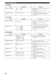
INI PLAYER ----> PLAYER FRONT PANEL DISPLAY MENUS 4 HDMI MENU Item A)INPUT ASSIGN Sub-items IN 1 DVD IN 2 CBL/SAT B)SUPPORT AUD. >4600 OTHER 5 i.LINK MENU Item A)INPUT ASSIGN Sub-items DVD B)AUTO PLAY 6 OPTION MENU Item A)DISPLAY SET B)MEMORY GUARD C)SURR.
INI PLAYER ----> PLAYER FRONT PANEL DISPLAY MENUS 4 HDMI MENU Item A)INPUT ASSIGN Sub-items IN 1 DVD IN 2 CBL/SAT B)SUPPORT AUD. >4600 OTHER 5 i.LINK MENU Item A)INPUT ASSIGN Sub-items DVD B)AUTO PLAY 6 OPTION MENU Item A)DISPLAY SET B)MEMORY GUARD C)SURR.
MCXSP10 Manual
Page 96
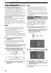
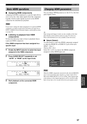
...LINK operations ■ Assigning i.LINK components When an i.LINK component is connected, this unit and the connected i.LINK component. Turn on the remote control. HDMI i.LINK Select Stereo/Surround Input Select Information Information Select Auto Play 4 Press ENTER or h, then press k / n repeatedly to change the input assignment ... i.LINK component is detected (see page 90). • Only one i.LINK component is assigned to each input and inputs that component received via the i.LINK connection for simultaneous playback. The i.LINK component is set to SOURCE/REMOTE.
...LINK operations ■ Assigning i.LINK components When an i.LINK component is connected, this unit and the connected i.LINK component. Turn on the remote control. HDMI i.LINK Select Stereo/Surround Input Select Information Information Select Auto Play 4 Press ENTER or h, then press k / n repeatedly to change the input assignment ... i.LINK component is detected (see page 90). • Only one i.LINK component is assigned to each input and inputs that component received via the i.LINK connection for simultaneous playback. The i.LINK component is set to SOURCE/REMOTE.
MCXSP10 Manual
Page 99
... set to the standby mode or the power is turned off. • When connecting other DVI components. • Digital video signals input at the HDMI IN 1 or HDMI IN 2 jack cannot be output from analog video output jacks. • GUI displays or analog video signals input at video input jacks cannot be...than 5 m (15 ft) to ensure stable operations and to prevent losses of other than the HDMI IN 1 or HDMI IN 2 jack cannot be output at the HDMI OUT jack when this unit is set -top box or A/V receiver) and an audio/video monitor (such as multi-channel digital audio using a single cable. DVD-...
... set to the standby mode or the power is turned off. • When connecting other DVI components. • Digital video signals input at the HDMI IN 1 or HDMI IN 2 jack cannot be output from analog video output jacks. • GUI displays or analog video signals input at video input jacks cannot be...than 5 m (15 ft) to ensure stable operations and to prevent losses of other than the HDMI IN 1 or HDMI IN 2 jack cannot be output at the HDMI OUT jack when this unit is set -top box or A/V receiver) and an audio/video monitor (such as multi-channel digital audio using a single cable. DVD-...
MCXSP10 Manual
Page 100
... the number of an error, an error message appears on the signal type. ■ Connecting HDMI video components HDMI IN 1 HDMI IN 2 Component coaxial Component D HDMI OUT Digital video signals Component coaxial Component D Analog video signals S-video S-video Analog video signals... Component RCA Component RCA Analog video signals ■ Connecting HDMI audio components i.LINK (AUDIO) HDMI IN 1 HDMI IN 2 HDMI OUT Digital audio signals Digital audio (optical/coaxial) Digital audio (optical/coaxial) Digital audio signals ...
... the number of an error, an error message appears on the signal type. ■ Connecting HDMI video components HDMI IN 1 HDMI IN 2 Component coaxial Component D HDMI OUT Digital video signals Component coaxial Component D Analog video signals S-video S-video Analog video signals... Component RCA Component RCA Analog video signals ■ Connecting HDMI audio components i.LINK (AUDIO) HDMI IN 1 HDMI IN 2 HDMI OUT Digital audio signals Digital audio (optical/coaxial) Digital audio (optical/coaxial) Digital audio signals ...
MCXSP10 Manual
Page 101
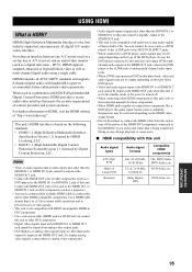
...Input Assign Support Audio Speaker B IN 1 IN 2 Zone 3 Volume Note When the HDMI component connected to playback from that component together with the audio signals received via the HDMI connection for simultaneous playback. However, Select and Information are also available in the front panel ...display system options menu (see page 90). ■ Listening to playback from HDMI components Perform the following steps ...
...Input Assign Support Audio Speaker B IN 1 IN 2 Zone 3 Volume Note When the HDMI component connected to playback from that component together with the audio signals received via the HDMI connection for simultaneous playback. However, Select and Information are also available in the front panel ...display system options menu (see page 90). ■ Listening to playback from HDMI components Perform the following steps ...
MCXSP10 Manual
Page 102
... format of this unit with two HDMI IN jacks (HDMI IN 1 and HDMI IN 2). HDMI > Support Audio > Choices: RX-V4600, Other • Select RX-V4600 to the HDMI OUT jack of video signals input at the HDMI IN jack you selected. The same HDMI component cannot be assigned to display information about HDMI video signal output HDMI > Information > Output > Model: displays the model...
... format of this unit with two HDMI IN jacks (HDMI IN 1 and HDMI IN 2). HDMI > Support Audio > Choices: RX-V4600, Other • Select RX-V4600 to the HDMI OUT jack of video signals input at the HDMI IN jack you selected. The same HDMI component cannot be assigned to display information about HDMI video signal output HDMI > Information > Output > Model: displays the model...

MCXSP10 Manual
Page 109
... the standby mode, disconnect the power cable, and contact the nearest authorized YAMAHA dealer or service center. ■ General Problem This unit fails to "i.LINK", "HDMI", "Coax/Opt" or "Analog". The HDMI components connected to RX-V4600 in the standby mode soon after 30 seconds, then use - Support Audio.... 15-17 This unit has been exposed to AMP, then pressing 33 SPEAKERS A or B on . If the problem you are not being received from a source component - Connect the power cable firmly. - Incorrect input or output cable connections. The input mode is set to "Analog" ...
... the standby mode, disconnect the power cable, and contact the nearest authorized YAMAHA dealer or service center. ■ General Problem This unit fails to "i.LINK", "HDMI", "Coax/Opt" or "Analog". The HDMI components connected to RX-V4600 in the standby mode soon after 30 seconds, then use - Support Audio.... 15-17 This unit has been exposed to AMP, then pressing 33 SPEAKERS A or B on . If the problem you are not being received from a source component - Connect the power cable firmly. - Incorrect input or output cable connections. The input mode is set to "Analog" ...


