
Owner's Manual
Page 1
DIGITAL MIXING CONSOLE PM5D / PM5D-RH Owner's Manual
DIGITAL MIXING CONSOLE PM5D / PM5D-RH Owner's Manual
Owner's Manual
Page 6
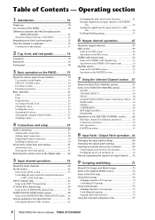
... Operating section 1 Introduction 10 Thank you 10 An overview of the PM5D 10 Differences between the PM5D model and the PM5D-RH model 11 About the channel structure of the PM5D 12 Regarding word clock synchronization 12 How this manual is organized 13 Conventions in this manual 13 2 Top, front, and rear panels 14 Top panel 14...
... Operating section 1 Introduction 10 Thank you 10 An overview of the PM5D 10 Differences between the PM5D model and the PM5D-RH model 11 About the channel structure of the PM5D 12 Regarding word clock synchronization 12 How this manual is organized 13 Conventions in this manual 13 2 Top, front, and rear panels 14 Top panel 14...
Owner's Manual
Page 7
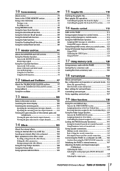
...MODE section 139 Assigning channels to DCA faders 139 Controlling the channels assigned to DCA faders 140 Locking the PM5D (Security functions 141 Setting the System Password or Console Password.......... 141 Using Parameter Lock or Console Lock ...PM5D to a computer via USB ..........146 Caution when using the USB TO HOST connector ........ 146 Initializing the PM5D's internal memory 147 Adjusting the faders and input/output gain (Calibration 147 Calibrating the faders 148 Adjusting the analog input gain (PM5D-RH model only 148 Adjusting the output gain 148 PM5D/PM5D-RH Owner's Manual...
...MODE section 139 Assigning channels to DCA faders 139 Controlling the channels assigned to DCA faders 140 Locking the PM5D (Security functions 141 Setting the System Password or Console Password.......... 141 Using Parameter Lock or Console Lock ...PM5D to a computer via USB ..........146 Caution when using the USB TO HOST connector ........ 146 Initializing the PM5D's internal memory 147 Adjusting the faders and input/output gain (Calibration 147 Calibrating the faders 148 Adjusting the analog input gain (PM5D-RH model only 148 Adjusting the output gain 148 PM5D/PM5D-RH Owner's Manual...
Owner's Manual
Page 8
... CH VIEW (Channel view) screen 245 SIGNAL FLOW screen 247 FADER VIEW screen 249 CH COPY (Channel copy) screen 249 OUTPUT CH LIBRARY screen 251 8 PM5D/PM5D-RH Owner's Manual Table of Contents -
... CH VIEW (Channel view) screen 245 SIGNAL FLOW screen 247 FADER VIEW screen 249 CH COPY (Channel copy) screen 249 OUTPUT CH LIBRARY screen 251 8 PM5D/PM5D-RH Owner's Manual Table of Contents -
Owner's Manual
Page 9
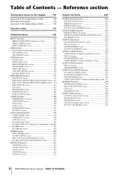
... Other Functions 354 Pin Assignment 355 Dimensions 356 MIDI Implementation Chart 357 Index 358 PM5D/PM5D-RH Block Diagram End of Manual PM5D Level Diagram End of Manual PM5D-RH Level Diagram End of Manual • The illustrations and screen displays as shown in this Owner's Manual are for instructional purposes only, and may be different from the ones on...
... Other Functions 354 Pin Assignment 355 Dimensions 356 MIDI Implementation Chart 357 Index 358 PM5D/PM5D-RH Block Diagram End of Manual PM5D Level Diagram End of Manual PM5D-RH Level Diagram End of Manual • The illustrations and screen displays as shown in this Owner's Manual are for instructional purposes only, and may be different from the ones on...
Owner's Manual
Page 10
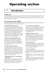
...I /O card expansion The rear panel provides four slots in . You can choose the model appropriate for each input, the PM5D-RH model is also available, providing programmable control of cutting-edge digital audio processing technology. 24-bit linear AD/DA converters are ...PM5D/PM5D-RH Owner's Manual Operating section After you begin using the product. An overview of the PM5D The PM5D is a digital mixing console with the following features. ❏ Full digital SR mixing system The PM5D is included as an Add-On Effect for purchasing the Yamaha PM5D digital mixing console. The PM5D...
...I /O card expansion The rear panel provides four slots in . You can choose the model appropriate for each input, the PM5D-RH model is also available, providing programmable control of cutting-edge digital audio processing technology. 24-bit linear AD/DA converters are ...PM5D/PM5D-RH Owner's Manual Operating section After you begin using the product. An overview of the PM5D The PM5D is a digital mixing console with the following features. ❏ Full digital SR mixing system The PM5D is included as an Add-On Effect for purchasing the Yamaha PM5D digital mixing console. The PM5D...
Owner's Manual
Page 11
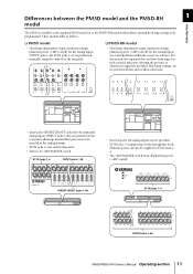
.... instead, indicators showing the presence or absence of the top panel. ❏ PM5D-RH model • Head amp adjustments (input sensitivity settings, phantom power (+48V) on /off) for the analog inputs are performed manually, using the controls of a signal are not provided. • ST IN jacks...support mic levels through line levels. INSERT IN/OUT jacks 1-48 ST IN jacks 1-4 INPUT jacks 1-48 PM5D/PM5D-RH Owner's Manual Operating section 11 These models differ as the PM5D-RH model which allows internal head amp settings to be programmed. Phantom power can be saved in a library and...
.... instead, indicators showing the presence or absence of the top panel. ❏ PM5D-RH model • Head amp adjustments (input sensitivity settings, phantom power (+48V) on /off) for the analog inputs are performed manually, using the controls of a signal are not provided. • ST IN jacks...support mic levels through line levels. INSERT IN/OUT jacks 1-48 ST IN jacks 1-4 INPUT jacks 1-48 PM5D/PM5D-RH Owner's Manual Operating section 11 These models differ as the PM5D-RH model which allows internal head amp settings to be programmed. Phantom power can be saved in a library and...
Owner's Manual
Page 12
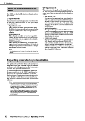
... to or from an external device via the PM5D's digital input/output jacks or via the 2TR IN/OUT DIGITAL jacks. 12 PM5D/PM5D-RH Owner's Manual Operating section Hint • For details on synchronizing the word clock of the PM5D and external devices, refer to these channels. ...2 Introduction About the channel structure of the PM5D The PM5D provides the following input channels and output ...
... to or from an external device via the PM5D's digital input/output jacks or via the 2TR IN/OUT DIGITAL jacks. 12 PM5D/PM5D-RH Owner's Manual Operating section Hint • For details on synchronizing the word clock of the PM5D and external devices, refer to these channels. ...2 Introduction About the channel structure of the PM5D The PM5D provides the following input channels and output ...
Owner's Manual
Page 13
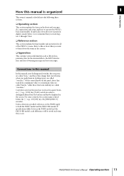
... and the PM5D-RH model. If specifications differ between the PM5D model and the PM5D-RH model, such differences will be noted each time they occur. Of the control knobs on the panel are called "switches." Refer to this section when you want to learn about the items in the screen. How this manual is organized...
... and the PM5D-RH model. If specifications differ between the PM5D model and the PM5D-RH model, such differences will be noted each time they occur. Of the control knobs on the panel are called "switches." Refer to this section when you want to learn about the items in the screen. How this manual is organized...
Owner's Manual
Page 14
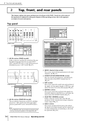
... jacks 1-48 and ST IN jacks 1-4, and switch pad, insert, and phantom power (+48 V) on/off (➥ p.35). (PM5D-RH model) 2 B AD IN section (PM5D-RH model) This area indicates the presence, peak level, and phantom power (+48V) on/off status of the input signal from input channels ...This chapter explains the names and functions of each section of the top panel are controlled by key operations (➥ p.100). 14 PM5D/PM5D-RH Owner's Manual Operating section H Meter section This section contains peak level meters that indicate the input levels of input channels and the output levels ...
... jacks 1-48 and ST IN jacks 1-4, and switch pad, insert, and phantom power (+48 V) on/off (➥ p.35). (PM5D-RH model) 2 B AD IN section (PM5D-RH model) This area indicates the presence, peak level, and phantom power (+48V) on/off status of the input signal from input channels ...This chapter explains the names and functions of each section of the top panel are controlled by key operations (➥ p.100). 14 PM5D/PM5D-RH Owner's Manual Operating section H Meter section This section contains peak level meters that indicate the input levels of input channels and the output levels ...
Owner's Manual
Page 15
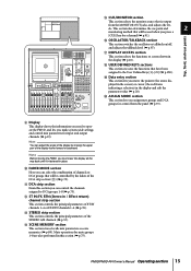
... groups for a channel (➥ p.91). R USER DEFINED KEYS sections This section executes the functions that will be controlled by moving the PM5D, you must lower the display all the way back until it is output from the panel (➥ p.73). T ASSIGN MODE section This... Mute operations for input and output channels (➥ p.19). els. L ST IN/FX RTN (Stereo in the display (➥ p.20). PM5D/PM5D-RH Owner's Manual Operating section 15 S Data entry section This section lets you make system-wide settings and control mix parameters for mute groups 1-8 are also performed in...
... groups for a channel (➥ p.91). R USER DEFINED KEYS sections This section executes the functions that will be controlled by moving the PM5D, you must lower the display all the way back until it is output from the panel (➥ p.73). T ASSIGN MODE section This... Mute operations for input and output channels (➥ p.19). els. L ST IN/FX RTN (Stereo in the display (➥ p.20). PM5D/PM5D-RH Owner's Manual Operating section 15 S Data entry section This section lets you make system-wide settings and control mix parameters for mute groups 1-8 are also performed in...
Owner's Manual
Page 16
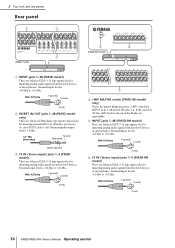
... devices. Nominal input level is -62 dBu to +10 dBu. Male XLR plug 1 (ground) 3 (cold) 2 (hot) 16 PM5D/PM5D-RH Owner's Manual Operating section 2 Top, front, and rear panels Rear panel 3 1 2 (PM5D model) 4 6 (PM5D-RH model) A INPUT jacks 1-48 (PM5D model) These are balanced XLR-3-31 type input jacks for inputting analog audio signals from line level devices...
... devices. Nominal input level is -62 dBu to +10 dBu. Male XLR plug 1 (ground) 3 (cold) 2 (hot) 16 PM5D/PM5D-RH Owner's Manual Operating section 2 Top, front, and rear panels Rear panel 3 1 2 (PM5D model) 4 6 (PM5D-RH model) A INPUT jacks 1-48 (PM5D model) These are balanced XLR-3-31 type input jacks for inputting analog audio signals from line level devices...
Owner's Manual
Page 17
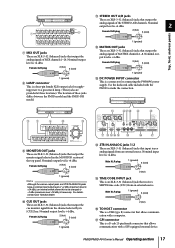
...that input stereo analog signals from an external source. Nominal output level is +4 dBu. Nominal output level is +4 dBu. For details, contact your Yamaha dealer. The location of the top panel. Female XLR plug 2 (hot) 3 (cold) 1 (ground) M DC POWER INPUT connector This is ...) 1 (ground) Note Although the various output jacks and 2TR IN ANALOG jacks have a nominal input/output level of MATRIX channels 1-8. PM5D/PM5D-RH Owner's Manual Operating section 17 Nominal input level is +24 dBu), an internal switch allows this to be changed to make the connection. Male XLR...
...that input stereo analog signals from an external source. Nominal output level is +4 dBu. Nominal output level is +4 dBu. For details, contact your Yamaha dealer. The location of the top panel. Female XLR plug 2 (hot) 3 (cold) 1 (ground) M DC POWER INPUT connector This is ...) 1 (ground) Note Although the various output jacks and 2TR IN ANALOG jacks have a nominal input/output level of MATRIX channels 1-8. PM5D/PM5D-RH Owner's Manual Operating section 17 Nominal input level is +24 dBu), an internal switch allows this to be changed to make the connection. Male XLR...
Owner's Manual
Page 18
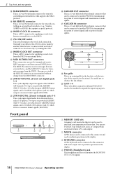
...jacks input digital audio from external MIDI devices. Normally you monitor the MONITOR OUT or CUE signals. 18 PM5D/PM5D-RH Owner's Manual Operating section Be careful not to the PM5D. Messages received at the MIDI IN connector are used to and from external devices such as CD players... Top, front, and rear panels R RS422 REMOTE connector This is a D-sub 9-pin male connector for remotely controlling an external head amp device (e.g., Yamaha AD8HR or AD824) that supports a special protocol. b c b Fan grille This is a BNC connector for supplying a word clock from the MIDI THRU...
...jacks input digital audio from external MIDI devices. Normally you monitor the MONITOR OUT or CUE signals. 18 PM5D/PM5D-RH Owner's Manual Operating section Be careful not to the PM5D. Messages received at the MIDI IN connector are used to and from external devices such as CD players... Top, front, and rear panels R RS422 REMOTE connector This is a D-sub 9-pin male connector for remotely controlling an external head amp device (e.g., Yamaha AD8HR or AD824) that supports a special protocol. b c b Fan grille This is a BNC connector for supplying a word clock from the MIDI THRU...
Owner's Manual
Page 19
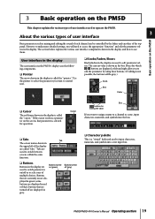
...Buttons turned off (gray) ❏ Character palette This is called the "pointer." User interface in the display The user interface in the PM5D's display uses the following components. ❏ Pointer The arrow shown in the display is a "virtual" keyboard used to input characters, numerals...value If you want to assign a name to a channel or scene, input characters, numerals, and symbols into a text input box. PM5D/PM5D-RH Owner's Manual Operating section 19 Buttons that are currently on the screen, that are turned off are called the "cursor." Cursor Box / buttons for ...
...Buttons turned off (gray) ❏ Character palette This is called the "pointer." User interface in the display The user interface in the PM5D's display uses the following components. ❏ Pointer The arrow shown in the display is a "virtual" keyboard used to input characters, numerals...value If you want to assign a name to a channel or scene, input characters, numerals, and symbols into a text input box. PM5D/PM5D-RH Owner's Manual Operating section 19 Buttons that are currently on the screen, that are turned off are called the "cursor." Cursor Box / buttons for ...
Owner's Manual
Page 20
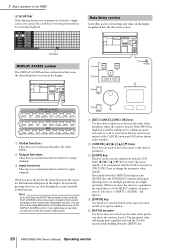
... section contains keys that are gathered into a single screen, you turn the [DATA] encoder while holding down the [SHIFT] key. 20 PM5D/PM5D-RH Owner's Manual Operating section B Output functions These keys access functions that access the desired function or screen in the display. If you rapidly press a key...related to input channels. C [SHIFT] key This key can also use the scroll bar to view the portion that affect the entire PM5D. Data Entry section Controllers used instead of the parameter where the cursor is not currently displayed. By repeatedly pressing a key you press...
... section contains keys that are gathered into a single screen, you turn the [DATA] encoder while holding down the [SHIFT] key. 20 PM5D/PM5D-RH Owner's Manual Operating section B Output functions These keys access functions that access the desired function or screen in the display. If you rapidly press a key...related to input channels. C [SHIFT] key This key can also use the scroll bar to view the portion that affect the entire PM5D. Data Entry section Controllers used instead of the parameter where the cursor is not currently displayed. By repeatedly pressing a key you press...
Owner's Manual
Page 21
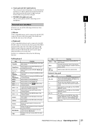
... the SCENE MEMORY section Same function as the [†] key of the SCENE MEMORY section Not used Same function as the [RECALL] key of the PM5D and used in the same way as the track pad. ❏ Keyboard A PS/2 compatible keyboard can be connected to recall scenes. Full keyboard Key... ❏ Mouse A PS/2 compatible mouse can be connected to the MOUSE connector located on ), input numerical values (if off ) PM5D/PM5D-RH Owner's Manual Operating section 21 Switch screens within the same function Accesses the function menu (if the function menu is a stereo phone jack for connecting...
... the SCENE MEMORY section Same function as the [†] key of the SCENE MEMORY section Not used Same function as the [RECALL] key of the PM5D and used in the same way as the track pad. ❏ Keyboard A PS/2 compatible keyboard can be connected to recall scenes. Full keyboard Key... ❏ Mouse A PS/2 compatible mouse can be connected to the MOUSE connector located on ), input numerical values (if off ) PM5D/PM5D-RH Owner's Manual Operating section 21 Switch screens within the same function Accesses the function menu (if the function menu is a stereo phone jack for connecting...
Owner's Manual
Page 22
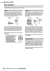
... parameter in the screen and pressing the left/right track pad button (or the left /right is called "dragging and dropping." 22 PM5D/PM5D-RH Owner's Manual Operating section If you are using a PS/2 keyboard, you can move the pointer to the desired parameter and then tap the track ...pad to dragging. Click Moving the pointer to another channel. Subsequently in this manual, this operation will simply be called "clicking." Dragging and dropping cannot be called "dragging." Drag and drop Moving the mouse pointer to...
... parameter in the screen and pressing the left/right track pad button (or the left /right is called "dragging and dropping." 22 PM5D/PM5D-RH Owner's Manual Operating section If you are using a PS/2 keyboard, you can move the pointer to the desired parameter and then tap the track ...pad to dragging. Click Moving the pointer to another channel. Subsequently in this manual, this operation will simply be called "clicking." Dragging and dropping cannot be called "dragging." Drag and drop Moving the mouse pointer to...
Owner's Manual
Page 23
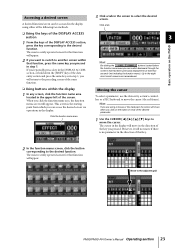
...below the function name area you pressed. However, it will not move if there is the starting point from which you click on the PM5D ❏ Using the keys of the DISPLAY ACCESS section 1 From the keys of the key you can access the desired screen via operations... function name area Moving the cursor To select a parameter, use the data entry section's controllers or a PS/2 keyboard to the adjacent grid PM5D/PM5D-RH Owner's Manual Operating section 23 When you pressed in step 1. Up to select the desired screen. The most recent screens are using either of the screen....
...below the function name area you pressed. However, it will not move if there is the starting point from which you click on the PM5D ❏ Using the keys of the DISPLAY ACCESS section 1 From the keys of the key you can access the desired screen via operations... function name area Moving the cursor To select a parameter, use the data entry section's controllers or a PS/2 keyboard to the adjacent grid PM5D/PM5D-RH Owner's Manual Operating section 23 When you pressed in step 1. Up to select the desired screen. The most recent screens are using either of the screen....
Owner's Manual
Page 24
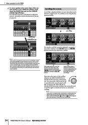
...] encoder clockwise, the screen will move the cursor toward the left (or upward, in a single screen. If you turn the encoder. 24 PM5D/PM5D-RH Owner's Manual Operating section To scroll the screen, drag the box shown in the bar. ➠ [SHIFT] key + CURSOR [®] key Drag You ...the [DATA] encoder clockwise will move the cursor downward, and turning it counterclockwise will scroll toward the left . 3 Basic operation on the PM5D 2 To move quickly to the outer edge of vertical scrolling). the screen will move in larger steps than can also scroll the screen by ...
...] encoder clockwise, the screen will move the cursor toward the left (or upward, in a single screen. If you turn the encoder. 24 PM5D/PM5D-RH Owner's Manual Operating section To scroll the screen, drag the box shown in the bar. ➠ [SHIFT] key + CURSOR [®] key Drag You ...the [DATA] encoder clockwise will move the cursor downward, and turning it counterclockwise will scroll toward the left . 3 Basic operation on the PM5D 2 To move quickly to the outer edge of vertical scrolling). the screen will move in larger steps than can also scroll the screen by ...

