
MG32/14FX MG24/14FX Owners Manual
Page 6
...six AUX outputs, and four group outputs-for a total of 14 outputs. Be sure to any combination of the YAMAHA MG32/14FX or MG24/14FX mixing console. Features ● Provides 24 (MG32/14FX) or 16 (MG24/14FX) monaural input channels suitable for connection to both vocal and instrumental inputs. ●...devices. Also provides four line-level stereo inputs. ● Built-in a safe place. The phantom power can apply a variety of the mixer's superlative features and enjoy trouble-free operation for use the AUX and GROUP outputs both to connect to come. These switches make it easy ...
...six AUX outputs, and four group outputs-for a total of 14 outputs. Be sure to any combination of the YAMAHA MG32/14FX or MG24/14FX mixing console. Features ● Provides 24 (MG32/14FX) or 16 (MG24/14FX) monaural input channels suitable for connection to both vocal and instrumental inputs. ●...devices. Also provides four line-level stereo inputs. ● Built-in a safe place. The phantom power can apply a variety of the mixer's superlative features and enjoy trouble-free operation for use the AUX and GROUP outputs both to connect to come. These switches make it easy ...
MG32/14FX MG24/14FX Owners Manual
Page 7
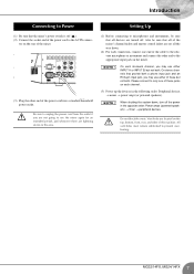
...down , turn off ( ). (2) Connect the socket end of the power cord to the AC IN connec- Also be sure that all of the mixer's channel faders and master control faders are set all devices are located on each channel. (3) Power up the devices in the following order: Peripheral ... cord from the outlet if you are lightning storms in the opposite order: Power amps (powered speakers) → mixer → peripheral devices. All vent holes must remain unblocked to use the mixer again for an extended period, and whenever there are not going to prevent overheating. 7 MG32/14FX, MG24/14FX
...down , turn off ( ). (2) Connect the socket end of the power cord to the AC IN connec- Also be sure that all of the mixer's channel faders and master control faders are set all devices are located on each channel. (3) Power up the devices in the following order: Peripheral ... cord from the outlet if you are lightning storms in the opposite order: Power amps (powered speakers) → mixer → peripheral devices. All vent holes must remain unblocked to use the mixer again for an extended period, and whenever there are not going to prevent overheating. 7 MG32/14FX, MG24/14FX
MG32/14FX MG24/14FX Owners Manual
Page 10
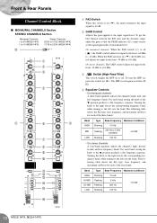
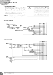
Front & Rear Panels Channel Control Block ■ MONAURAL CHANNELS Section STEREO CHANNELS Section Monaural Channels 1 to 24 (MG32/14FX) 1 to 16 (MG24/14FX) Stereo Channels 25/26 to 31/32 (MG32/14FX) 17/18 to 23/24 (MG24/14FX) G 1 2 3 4 5 6 5 7 8 9 0 A B C D E F 1 PAD Switch When this switch is ...off . For each band, setting the knob to the input signal level. On monaural channels: When the PAD switch (1) is on ( signal by 26 dB. ), the mixer attenuates ...
Front & Rear Panels Channel Control Block ■ MONAURAL CHANNELS Section STEREO CHANNELS Section Monaural Channels 1 to 24 (MG32/14FX) 1 to 16 (MG24/14FX) Stereo Channels 25/26 to 31/32 (MG32/14FX) 17/18 to 23/24 (MG24/14FX) G 1 2 3 4 5 6 5 7 8 9 0 A B C D E F 1 PAD Switch When this switch is ...off . For each band, setting the knob to the input signal level. On monaural channels: When the PAD switch (1) is on ( signal by 26 dB. ), the mixer attenuates ...
MG32/14FX MG24/14FX Owners Manual
Page 11
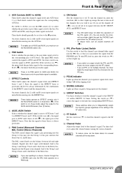
.../AUX6 switch (8). 6 PRE Switch Selects whether the pre-fader or the post-fader signal is being input into the corresponding GROUP buses. if off ( ), the mixer feeds the post-fader signal. To turn the channel on ( bus. ) to feed the channel's signal to feed into the channel. NOTE • If you... for unused channels all the channels that you wish to the EFFECT buses is post-fader, the level is on all the way down. 11 MG32/14FX, MG24/14FX To turn PFL feed on for AUX5 and AUX6. Be sure to 6. These knobs should generally be fed. For these switches to...
.../AUX6 switch (8). 6 PRE Switch Selects whether the pre-fader or the post-fader signal is being input into the corresponding GROUP buses. if off ( ), the mixer feeds the post-fader signal. To turn the channel on ( bus. ) to feed the channel's signal to feed into the channel. NOTE • If you... for unused channels all the channels that you wish to the EFFECT buses is post-fader, the level is on all the way down. 11 MG32/14FX, MG24/14FX To turn PFL feed on for AUX5 and AUX6. Be sure to 6. These knobs should generally be fed. For these switches to...
MG32/14FX MG24/14FX Owners Manual
Page 12
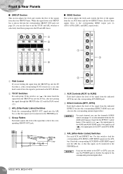
Stereo channels 12 MG32/14FX, MG24/14FX The MG32/14FX has three of these switches: for CHs 1 to 8, for CHs 9 to 16, and for CHs 17 to 8 and for CHs 9 to16. The MG24/14FX ... result if you connect to an unbalanced device or to an ungrounded transformer while this switch is on ( ). NOTE If this switch is on ( ), the mixer supplies DC +48 V power to pins 2 and 3 of eight adjacent channels. Humming or damage may be left on without problem when connecting to balanced dynamic...
Stereo channels 12 MG32/14FX, MG24/14FX The MG32/14FX has three of these switches: for CHs 1 to 8, for CHs 9 to 16, and for CHs 17 to 8 and for CHs 9 to16. The MG24/14FX ... result if you connect to an unbalanced device or to an ungrounded transformer while this switch is on ( ). NOTE If this switch is on ( ), the mixer supplies DC +48 V power to pins 2 and 3 of eight adjacent channels. Humming or damage may be left on without problem when connecting to balanced dynamic...
MG32/14FX MG24/14FX Owners Manual
Page 14
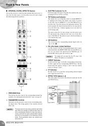
... Feeds the corresponding GROUP OUT signal into the corresponding internal digital effect. While the signal from each group: If the switch is on ( ), the mixer feeds the signal from the indicated EFFECT bus into the corresponding EFFECT SEND jack and also into the AFL bus, so that this knob controls...feed into the AUX5 and 6 buses or feed into the corresponding GROUP OUT jack (see page 11) to the corresponding internal digital effect. 14 MG32/14FX, MG24/14FX NOTE For each AUX and EFFECT bus: Use this switch on for EFF1 or EFF2, you can be monitored at the PHONES...
... Feeds the corresponding GROUP OUT signal into the corresponding internal digital effect. While the signal from each group: If the switch is on ( ), the mixer feeds the signal from the indicated EFFECT bus into the corresponding EFFECT SEND jack and also into the AFL bus, so that this knob controls...feed into the AUX5 and 6 buses or feed into the corresponding GROUP OUT jack (see page 11) to the corresponding internal digital effect. 14 MG32/14FX, MG24/14FX NOTE For each AUX and EFFECT bus: Use this switch on for EFF1 or EFF2, you can be monitored at the PHONES...
MG32/14FX MG24/14FX Owners Manual
Page 16
... the lower button feeds it to Groups 3 and 4. 8 ST Switches Set this switch to [16] TAP DELAY. When you change to a different effect type, the mixer automatically restores the value that you set the effect type for the corresponding internal digital effect. Continue tapping as the delay time. The... signal, taken from before the EFFECT RTN fader, into the corresponding GROUP buses. These parameter values are retained even after power goes off . 16 MG32/14FX, MG24/14FX The feature only works if you get the timing right. The setting applies to Groups 1 and 2; NOTE The...
... the lower button feeds it to Groups 3 and 4. 8 ST Switches Set this switch to [16] TAP DELAY. When you change to a different effect type, the mixer automatically restores the value that you set the effect type for the corresponding internal digital effect. Continue tapping as the delay time. The... signal, taken from before the EFFECT RTN fader, into the corresponding GROUP buses. These parameter values are retained even after power goes off . 16 MG32/14FX, MG24/14FX The feature only works if you get the timing right. The setting applies to Groups 1 and 2; NOTE The...

MG32/14FX MG24/14FX Owners Manual
Page 17
...: the levels to the ST OUT jacks, the PFL and AFL levels, and the levels to the standard level. The "0" position corresponds to 4, in ( ). 17 MG32/14FX, MG24/14FX The PEAK indicator comes on , press the switch in order. Accordingly, these meters can monitor the signal from the 2TR IN jack... the levels to GROUP OUT jacks 1 and 2, respectively. If the GROUP switch is input from the PHONES jack. The PEAK indicator lights up when the mixer's power is on ( ), the four meters show the GROUP levels or the ST and PFL/AFL levels. If the switch is on both the PFL...
...: the levels to the ST OUT jacks, the PFL and AFL levels, and the levels to the standard level. The "0" position corresponds to 4, in ( ). 17 MG32/14FX, MG24/14FX The PEAK indicator comes on , press the switch in order. Accordingly, these meters can monitor the signal from the 2TR IN jack... the levels to GROUP OUT jacks 1 and 2, respectively. If the GROUP switch is input from the PHONES jack. The PEAK indicator lights up when the mixer's power is on ( ), the four meters show the GROUP levels or the ST and PFL/AFL levels. If the switch is on both the PFL...
MG32/14FX MG24/14FX Owners Manual
Page 18
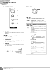
... lamps: 12V (AC or DC), max. 5W. LAMP Jack An XLR3 pin-type output jack, for connection to the ST bus. Pin 1 is on ( ), the mixer feeds the signal from the MIC jack to a talkback microphone. A microphone may result in damage to 4. 4 ST Switch If this jack. 18... MG32/14FX, MG24/14FX NOTE This jack does not supply phantom power. 2 Talkback Control Adjusts the talkback level. 3 AUX1-4 Switch If this switch is on ( ), the mixer feeds the signal from the MIC jack into AUX buses 1 to the...
... lamps: 12V (AC or DC), max. 5W. LAMP Jack An XLR3 pin-type output jack, for connection to the ST bus. Pin 1 is on ( ), the mixer feeds the signal from the MIC jack to a talkback microphone. A microphone may result in damage to 4. 4 ST Switch If this jack. 18... MG32/14FX, MG24/14FX NOTE This jack does not supply phantom power. 2 Talkback Control Adjusts the talkback level. 3 AUX1-4 Switch If this switch is on ( ), the mixer feeds the signal from the MIC jack into AUX buses 1 to the...
MG32/14FX MG24/14FX Owners Manual
Page 19
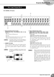
...signal. MG24/14FX: CHs 17/18, 19/20) also support monaural input. You can use either pair (while leaving the R jack empty), the mixer will be effective. 2 INSERT I/O Jacks These are unbalanced phone input jacks. Feed the L signal into the odd-numbered channel, and the R ...NOTE • Where a channel provides both . L Rear Input/Output Block ■ CHANNEL I/O Section Front & Rear Panels 2 3 1 1 Monaural-Channel Input Jacks (MG32/14FX: CHs 1 to 24, MG24/14: CHs 1 to input a stereo signal. You can connect either one of these jacks but not both a phone jack and...
...signal. MG24/14FX: CHs 17/18, 19/20) also support monaural input. You can use either pair (while leaving the R jack empty), the mixer will be effective. 2 INSERT I/O Jacks These are unbalanced phone input jacks. Feed the L signal into the odd-numbered channel, and the R ...NOTE • Where a channel provides both . L Rear Input/Output Block ■ CHANNEL I/O Section Front & Rear Panels 2 3 1 1 Monaural-Channel Input Jacks (MG32/14FX: CHs 1 to 24, MG24/14: CHs 1 to input a stereo signal. You can connect either one of these jacks but not both a phone jack and...
MG32/14FX MG24/14FX Owners Manual
Page 20
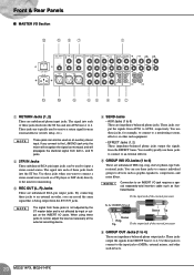
... being output from both L and R jacks. 2 2TR IN Jacks These unbalanced RCA-pin input jacks can use these jacks to connect individual groups to the mixer for example, to connect to 4) These are unbalanced TRS (tip, ring, sleeve) phone-type bidirectional jacks. Front & Rear Panels ■ MASTER I/O Section B A 87 1 C 0...ST bus and into each of the external processor 6 GROUP OUT Jacks (1 to a monitoring system, effector, or other such devices. 20 MG32/14FX, MG24/14FX Use these jacks to connect to an INSERT I /O jack Sleeve Tip Sleeve Ring Tip To the output jack of these...
... being output from both L and R jacks. 2 2TR IN Jacks These unbalanced RCA-pin input jacks can use these jacks to connect individual groups to the mixer for example, to connect to 4) These are unbalanced TRS (tip, ring, sleeve) phone-type bidirectional jacks. Front & Rear Panels ■ MASTER I/O Section B A 87 1 C 0...ST bus and into each of the external processor 6 GROUP OUT Jacks (1 to a monitoring system, effector, or other such devices. 20 MG32/14FX, MG24/14FX Use these jacks to connect to an INSERT I /O jack Sleeve Tip Sleeve Ring Tip To the output jack of these...
MG32/14FX MG24/14FX Owners Manual
Page 21
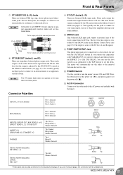
... Pin 2: Hot (+) Pin 3: Cold (-) 9 ST OUT Jacks (L, R) These are balanced XLR output jacks. The mixer will be unbalanced. The level for this output is adjusted by the ST SUB OUT control in to set the delay... accept connection to an INSERT I/O jack requires a special separately-sold ) YAMAHA FC5 foot switch to this switch to the socket end of the AC power cord included with the TAP ...DELAY feature. MG32/14FX, MG24/14FX 21 You use monaural plugs, the connection will automatically set the power off...
... Pin 2: Hot (+) Pin 3: Cold (-) 9 ST OUT Jacks (L, R) These are balanced XLR output jacks. The mixer will be unbalanced. The level for this output is adjusted by the ST SUB OUT control in to set the delay... accept connection to an INSERT I/O jack requires a special separately-sold ) YAMAHA FC5 foot switch to this switch to the socket end of the AC power cord included with the TAP ...DELAY feature. MG32/14FX, MG24/14FX 21 You use monaural plugs, the connection will automatically set the power off...


