

MG32/14FX MG24/14FX Owners Manual
Page 2
... the manufacturer's instructions. 8 Do not install near water. 6 Clean only with one wider than the other apparatus (including amplifiers) that may be of sufficient magnitude to qualified service personnel. The wide blade or the third prong are provided for replacement of the obsolete outlet. 10 Protect the power cord from being walked on the rear of the unit...
... the manufacturer's instructions. 8 Do not install near water. 6 Clean only with one wider than the other apparatus (including amplifiers) that may be of sufficient magnitude to qualified service personnel. The wide blade or the third prong are provided for replacement of the obsolete outlet. 10 Protect the power cord from being walked on the rear of the unit...
MG32/14FX MG24/14FX Owners Manual
Page 3
... the power switch is turned off the power switch and disconnect the plug from the AC outlet. Handling caution • Avoid setting all connected cables. • When setting up the product, make sure that the AC outlet you are not using is still flowing to disassemble the internal parts or modify them in any gaps or openings on the buttons, switches or connectors. 3 MG32/14FX...
... the power switch is turned off the power switch and disconnect the plug from the AC outlet. Handling caution • Avoid setting all connected cables. • When setting up the product, make sure that the AC outlet you are not using is still flowing to disassemble the internal parts or modify them in any gaps or openings on the buttons, switches or connectors. 3 MG32/14FX...
MG32/14FX MG24/14FX Owners Manual
Page 4
... use of the product during operation. Compliance with the letter N or coloured BLACK. Always turn the power off when the device is strictly prohibited. Yamaha cannot be the source of their respective owners. Insert TRS phone jacks are wired as switches, volume controls, and connectors, deteriorates over time. The performance of radio or TV interference, relocate/reorient the antenna. IMPORTANT: When connecting this Owner's Manual...
... use of the product during operation. Compliance with the letter N or coloured BLACK. Always turn the power off when the device is strictly prohibited. Yamaha cannot be the source of their respective owners. Insert TRS phone jacks are wired as switches, volume controls, and connectors, deteriorates over time. The performance of radio or TV interference, relocate/reorient the antenna. IMPORTANT: When connecting this Owner's Manual...
MG32/14FX MG24/14FX Owners Manual
Page 6
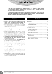
... input jacks, allowing you set the internal effect's delay time by tapping on a button (or by stepping on Yamaha's acclaimed SPX multi-effector technology, can use the AUX and GROUP outputs both microphones and line-level devices. Contents Introduction 6 Features 6 Connecting to retain this Owner's Manual carefully before beginning use as the main mixer in a safe place. Be sure to Power 7 Setting Up 7 Front & Rear Panels 8 Channel Control Block 10 Master Control Block 13 Rear Input/Output Block 19 Appendix 22 Specifications 22 Dimensional Diagrams 25 Block...
... input jacks, allowing you set the internal effect's delay time by tapping on a button (or by stepping on Yamaha's acclaimed SPX multi-effector technology, can use the AUX and GROUP outputs both microphones and line-level devices. Contents Introduction 6 Features 6 Connecting to retain this Owner's Manual carefully before beginning use as the main mixer in a safe place. Be sure to Power 7 Setting Up 7 Front & Rear Panels 8 Channel Control Block 10 Master Control Block 13 Rear Input/Output Block 19 Appendix 22 Specifications 22 Dimensional Diagrams 25 Block...
MG32/14FX MG24/14FX Owners Manual
Page 7
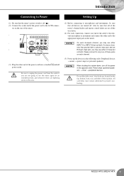
... to prevent overheating. 7 MG32/14FX, MG24/14FX NOTE On each channel. (3) Power up the devices in the following order: Peripheral devices → mixer → power amps (or powered speakers). Do not block the vents. Setting Up (1) Before connecting to microphones and instruments, be sure that all devices are set all of the mixer's channel faders and master control faders are turned off ( ). (2) Connect the socket end of the power cord to the AC...
... to prevent overheating. 7 MG32/14FX, MG24/14FX NOTE On each channel. (3) Power up the devices in the following order: Peripheral devices → mixer → power amps (or powered speakers). Do not block the vents. Setting Up (1) Before connecting to microphones and instruments, be sure that all devices are set all of the mixer's channel faders and master control faders are turned off ( ). (2) Connect the socket end of the power cord to the AC...
MG32/14FX MG24/14FX Owners Manual
Page 10
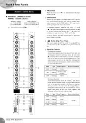
... cuts the band. Front & Rear Panels Channel Control Block ■ MONAURAL CHANNELS Section STEREO CHANNELS Section Monaural Channels 1 to 24 (MG32/14FX) 1 to 16 (MG24/14FX) Stereo Channels 25/26 to 31/32 (MG32/14FX) 17/18 to 23/24 (MG24/14FX) G 1 2 3 4 5 6 5 7 8 9 0 A B C D E F 1 PAD Switch When this switch is on or off ( ), the GAIN control adjusts for input levels from -34 dBu to +10 dBu. On stereo channels: The GAIN control adjusts for each of the...
... cuts the band. Front & Rear Panels Channel Control Block ■ MONAURAL CHANNELS Section STEREO CHANNELS Section Monaural Channels 1 to 24 (MG32/14FX) 1 to 16 (MG24/14FX) Stereo Channels 25/26 to 31/32 (MG32/14FX) 17/18 to 23/24 (MG24/14FX) G 1 2 3 4 5 6 5 7 8 9 0 A B C D E F 1 PAD Switch When this switch is on or off ( ), the GAIN control adjusts for input levels from -34 dBu to +10 dBu. On stereo channels: The GAIN control adjusts for each of the...
MG32/14FX MG24/14FX Owners Manual
Page 11
... channel off ( ), you use of the Stereo bus. Setting the switch on output to feed into the EFFECT bus. NOTE To reduce noise, set off. • To reduce noise, turn PFL feed on ( ), the mixer feeds the pre-fader signal to groups regardless of the setting of the channel's signal. If you can monitor the signal from the channels into the ST, GROUP, AUX, and EFFECT buses. E ST Switch Set this switch to adjust the volume balance among the various channels. the lower switch controls...
... channel off ( ), you use of the Stereo bus. Setting the switch on output to feed into the EFFECT bus. NOTE To reduce noise, set off. • To reduce noise, turn PFL feed on ( ), the mixer feeds the pre-fader signal to groups regardless of the setting of the channel's signal. If you can monitor the signal from the channels into the ST, GROUP, AUX, and EFFECT buses. E ST Switch Set this switch to adjust the volume balance among the various channels. the lower switch controls...
MG32/14FX MG24/14FX Owners Manual
Page 12
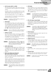
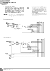
Front & Rear Panels G PHANTOM +48 V Switch Toggles phantom power on ( ). If using condenser microphones, set of eight adjacent channels. Humming or damage may be left on without problem when connecting to balanced dynamic microphones. • To avoid damage to speakers, be sure to turn off amplifiers (or powered speakers) before turning these switches on ( ), the mixer supplies DC +48 V power to pins 2 and 3 of these switches: for CHs 1 to 8, for CHs 9 to 16, and for...
Front & Rear Panels G PHANTOM +48 V Switch Toggles phantom power on ( ). If using condenser microphones, set of eight adjacent channels. Humming or damage may be left on without problem when connecting to balanced dynamic microphones. • To avoid damage to speakers, be sure to turn off amplifiers (or powered speakers) before turning these switches on ( ), the mixer supplies DC +48 V power to pins 2 and 3 of these switches: for CHs 1 to 8, for CHs 9 to 16, and for...
MG32/14FX MG24/14FX Owners Manual
Page 13
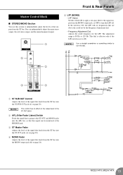
... be monitored at the PHONES jack. 3 ST Master Fader Adjusts the level of the signal that feeds from the ST bus. If the switch is 80 Hz to independently adjust the levels of the outputs from the ST bus into the ST OUT jacks (9 on page 20). 4 MONO Fader Adjusts the level of the signal that this signal can independently adjust the main stereo output, the sub stereo output, and the mixed monaural output. 1 5 LPF (MONO) • LPF Switch Set this switch ON...
... be monitored at the PHONES jack. 3 ST Master Fader Adjusts the level of the signal that feeds from the ST bus. If the switch is 80 Hz to independently adjust the levels of the outputs from the ST bus into the ST OUT jacks (9 on page 20). 4 MONO Fader Adjusts the level of the signal that this signal can independently adjust the main stereo output, the sub stereo output, and the mixed monaural output. 1 5 LPF (MONO) • LPF Switch Set this switch ON...
MG32/14FX MG24/14FX Owners Manual
Page 14
... knob controls how the signal is positioned on the ST L/R lines. 2 TO ST Switches For each group: If the switch is off ( ), the signal goes to the EFF1 and EFF2 SEND jacks. 3 AFL (After-Fader Listen) Switches For each channel, you are also free to use the TO ST and AFL switches to the corresponding internal digital effect. 14 MG32/14FX, MG24/14FX While the signal from the six AUX buses...
... knob controls how the signal is positioned on the ST L/R lines. 2 TO ST Switches For each group: If the switch is off ( ), the signal goes to the EFF1 and EFF2 SEND jacks. 3 AFL (After-Fader Listen) Switches For each channel, you are also free to use the TO ST and AFL switches to the corresponding internal digital effect. 14 MG32/14FX, MG24/14FX While the signal from the six AUX buses...

MG32/14FX MG24/14FX Owners Manual
Page 15
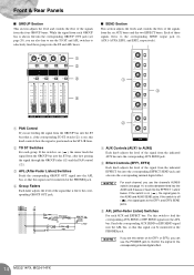
... AUX Mix controls, into the PFL bus, so that you are inputting a mono signal, the same signal is fed to both ST L and ST R. 3 PFL (Pre-Fader Listen) Switch Use this switch to feed the corresponding RETURN signal, taken from the corresponding RETURN jack into the ST bus. If you can set independent levels for feeds into the ST bus and AUX buses 1 to 4. 1 2 3 1 2 3 1 AUX Mix Controls (1 to 4) Each knob adjusts the level of the signal...
... AUX Mix controls, into the PFL bus, so that you are inputting a mono signal, the same signal is fed to both ST L and ST R. 3 PFL (Pre-Fader Listen) Switch Use this switch to feed the corresponding RETURN signal, taken from the corresponding RETURN jack into the ST bus. If you can set independent levels for feeds into the ST bus and AUX buses 1 to 4. 1 2 3 1 2 3 1 AUX Mix Controls (1 to 4) Each knob adjusts the level of the signal...
MG32/14FX MG24/14FX Owners Manual
Page 16
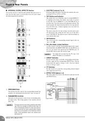
... set the delay time for internal EFFECT 2 by tapping on the button. The indicator next to the button flashes in ( ). The mixer retains the last time setting even after power-off . 7 GROUP Switches Set the switch on ( ) to feed the corresponding internal digital effect signal into the ST and GROUP buses. 9 1 PROGRAM Dials This dial sets the effect type for the corresponding internal digital effect. The setting applies to Groups 1 and 2; Front & Rear Panels ■ INTERNAL DIGITAL EFFECTS Section You use this section to control...
... set the delay time for internal EFFECT 2 by tapping on the button. The indicator next to the button flashes in ( ). The mixer retains the last time setting even after power-off . 7 GROUP Switches Set the switch on ( ) to feed the corresponding internal digital effect signal into the ST and GROUP buses. 9 1 PROGRAM Dials This dial sets the effect type for the corresponding internal digital effect. The setting applies to Groups 1 and 2; Front & Rear Panels ■ INTERNAL DIGITAL EFFECTS Section You use this section to control...

MG32/14FX MG24/14FX Owners Manual
Page 17
... PFL-AFL level meter (3) shows the level of the signal monitored through the PHONES jack. 4 5 ■ 2TR INPUT Section This section adjusts the signal that you can be monitored through the PHONES jack. 1 2 3 5 PHONES Jack and Control • PHONES Jack An unbalanced stereo phone output jack, for monitoring. The PEAK indicator lights up when the mixer's power is on. 2 STEREO Level Meters If the GROUP switch (4) is on , the left and right meters show the levels to the...
... PFL-AFL level meter (3) shows the level of the signal monitored through the PHONES jack. 4 5 ■ 2TR INPUT Section This section adjusts the signal that you can be monitored through the PHONES jack. 1 2 3 5 PHONES Jack and Control • PHONES Jack An unbalanced stereo phone output jack, for monitoring. The PEAK indicator lights up when the mixer's power is on. 2 STEREO Level Meters If the GROUP switch (4) is on , the left and right meters show the levels to the...
MG32/14FX MG24/14FX Owners Manual
Page 18
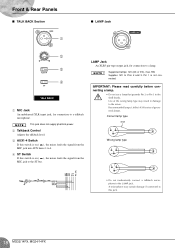
... connect a talkback microphone to the ST bus. NOTE This jack does not supply phantom power. 2 Talkback Control Adjusts the talkback level. 3 AUX1-4 Switch If this switch is on ( ), the mixer feeds the signal from the MIC jack into AUX buses 1 to 4. 4 ST Switch If this jack. 18 MG32/14FX, MG24/14FX Front & Rear Panels ■ TALK BACK Section 1 ■ LAMP Jack 2 3 4 1 MIC Jack An unbalanced XLR input jack, for connection to a lamp. LAMP Jack An XLR3 pin-type output jack, for connection...
... connect a talkback microphone to the ST bus. NOTE This jack does not supply phantom power. 2 Talkback Control Adjusts the talkback level. 3 AUX1-4 Switch If this switch is on ( ), the mixer feeds the signal from the MIC jack into AUX buses 1 to 4. 4 ST Switch If this jack. 18 MG32/14FX, MG24/14FX Front & Rear Panels ■ TALK BACK Section 1 ■ LAMP Jack 2 3 4 1 MIC Jack An unbalanced XLR input jack, for connection to a lamp. LAMP Jack An XLR3 pin-type output jack, for connection...
MG32/14FX MG24/14FX Owners Manual
Page 19
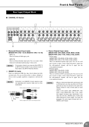
... input jacks. If you connect to both a phone jack and an RCA pin jack, you input only into the L (MONO) jack of the phone jacks (MG32/14FX: CHs 25/26, 27/28; Specifically, if you may use either pair (while leaving the R jack empty), the mixer will be effective. 2 INSERT I /O jack requires a special separately-sold insertion cable such as graphic equalizers, compressors, and noise filters. Please connect to input a stereo signal...
... input jacks. If you connect to both a phone jack and an RCA pin jack, you input only into the L (MONO) jack of the phone jacks (MG32/14FX: CHs 25/26, 27/28; Specifically, if you may use either pair (while leaving the R jack empty), the mixer will be effective. 2 INSERT I /O jack requires a special separately-sold insertion cable such as graphic equalizers, compressors, and noise filters. Please connect to input a stereo signal...
MG32/14FX MG24/14FX Owners Manual
Page 20
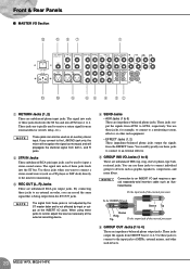
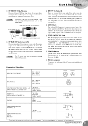
... output from the EFFECT buses. Front & Rear Panels ■ MASTER I/O Section B A 87 1 C 0 9 6 5 4 32 1 RETURN Jacks (1, 2) These are unbalanced TRS (tip, ring, sleeve) phone-type bidirectional jacks. Use these jacks, for monitoring. 3 REC OUT (L, R) Jacks These are impedance-balanced phone output jacks. These jacks output the signals from an external effector (reverb, delay, etc.). You use these jacks when you want to connect a stereo sound source (such as necessary at the INSERT I/O jacks. You can be used to a monitoring...
... output from the EFFECT buses. Front & Rear Panels ■ MASTER I/O Section B A 87 1 C 0 9 6 5 4 32 1 RETURN Jacks (1, 2) These are unbalanced TRS (tip, ring, sleeve) phone-type bidirectional jacks. Use these jacks, for monitoring. 3 REC OUT (L, R) Jacks These are impedance-balanced phone output jacks. These jacks output the signals from an external effector (reverb, delay, etc.). You use these jacks when you want to connect a stereo sound source (such as necessary at the INSERT I/O jacks. You can be used to a monitoring...
MG32/14FX MG24/14FX Owners Manual
Page 21
... master fader in the Master Control block (see page 13). C AC IN Connector Connects to turn the mixer's power ON and OFF. The level for use monaural plugs, the connection will automatically set the delay to the power amplifiers driving your main output, such as to the interval between the last two taps. A FOOT SWITCH TAP Jack This phone input jack is for this jack and then set internal EFFECT 2 to [16] TAP DELAY, you connect the (separately sold insertion cable...
... master fader in the Master Control block (see page 13). C AC IN Connector Connects to turn the mixer's power ON and OFF. The level for use monaural plugs, the connection will automatically set the delay to the power amplifiers driving your main output, such as to the interval between the last two taps. A FOOT SWITCH TAP Jack This phone input jack is for this jack and then set internal EFFECT 2 to [16] TAP DELAY, you connect the (separately sold insertion cable...
MG32/14FX MG24/14FX Owners Manual
Page 22
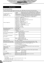
... 3 Internal Digital Effects MONO Low Pass Filter Monaural/Stereo Input Peak Indicator Monaural/Stereo Input Signal Indicator Level Meters Phantom +48 VDC Power (Balanced input) Included Accessory Option Lamp Power Supply Power Consumption Max. Dimensions (W × H × D) Weight 20 Hz-20 kHz +1 dB, -3 dB @+4 dBu, 600 Ω (with gain control at minimum level) Appendix Specifications ■ General Specifications Frequency Characteristics (Master Output) Total Harmonic Distortion (Master Output) Hum and Noise (20 Hz - 20 kHz) 1 Input GAIN = Maximum Input PAD = OFF Input...
... 3 Internal Digital Effects MONO Low Pass Filter Monaural/Stereo Input Peak Indicator Monaural/Stereo Input Signal Indicator Level Meters Phantom +48 VDC Power (Balanced input) Included Accessory Option Lamp Power Supply Power Consumption Max. Dimensions (W × H × D) Weight 20 Hz-20 kHz +1 dB, -3 dB @+4 dBu, 600 Ω (with gain control at minimum level) Appendix Specifications ■ General Specifications Frequency Characteristics (Master Output) Total Harmonic Distortion (Master Output) Hum and Noise (20 Hz - 20 kHz) 1 Input GAIN = Maximum Input PAD = OFF Input...
MG32/14FX MG24/14FX Owners Manual
Page 23
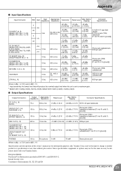
...fications ST OUT (L, R) MONO 75 Ω 600 Ω line +4 dBu (1.23 V) +24 dBu (12.3 V) XLR-3-32 type (balanced) GROUP OUT (1-4) AUX SEND (1-6) 150 Ω 600 Ω line +4 dBu (1.23 V) Phone jack (TRS) +20 dBu (7.75 V) (impedance balanced [T: hot; R: cold; Appendix ■ Input Specifications Input Connector PAD Gain Input Impedance Appropriate Impedance Sensitivity 1 Rated Level Max. Before Clipping Connector Speci...
...fications ST OUT (L, R) MONO 75 Ω 600 Ω line +4 dBu (1.23 V) +24 dBu (12.3 V) XLR-3-32 type (balanced) GROUP OUT (1-4) AUX SEND (1-6) 150 Ω 600 Ω line +4 dBu (1.23 V) Phone jack (TRS) +20 dBu (7.75 V) (impedance balanced [T: hot; R: cold; Appendix ■ Input Specifications Input Connector PAD Gain Input Impedance Appropriate Impedance Sensitivity 1 Rated Level Max. Before Clipping Connector Speci...

MG32/14FX MG24/14FX Owners Manual
Page 24
.... Produces a hard-sounding rever- Reverb time beration. 0.3-10.0 s Ideal reverb for vocals. DELAY A REVERB GATE B PITCH CHANGE C CHORUS D PHASER E RADIO VOICE F TREMOLO Monaural delay with the delay time. Modulates the delay time of the input signal. A GATE REVERB B VOCAL DOUBLER C SYMPHONIC D FLANGE E DISTORTION F TAP DELAY An effect produced by cutting the reverberation. Adds a sense of 256 ms (234.3 bpm). 24 MG32/14FX, MG24/14FX This effect sets the delay time to distort the sound. The amount...
.... Produces a hard-sounding rever- Reverb time beration. 0.3-10.0 s Ideal reverb for vocals. DELAY A REVERB GATE B PITCH CHANGE C CHORUS D PHASER E RADIO VOICE F TREMOLO Monaural delay with the delay time. Modulates the delay time of the input signal. A GATE REVERB B VOCAL DOUBLER C SYMPHONIC D FLANGE E DISTORTION F TAP DELAY An effect produced by cutting the reverberation. Adds a sense of 256 ms (234.3 bpm). 24 MG32/14FX, MG24/14FX This effect sets the delay time to distort the sound. The amount...


