

MG32/14FX MG24/14FX Owners Manual
Page 1
MIXING CONSOLE Owner's Manual MG32/14 FX MG24/14 FX E
MIXING CONSOLE Owner's Manual MG32/14 FX MG24/14 FX E
MG32/14FX MG24/14FX Owners Manual
Page 3
...CAREFULLY BEFORE PROCEEDING * Please keep this manual in damp or wet conditions, or place containers on it , and avoid use this device... • Do not insert your weight on the device or place heavy objects on the buttons, switches or connectors. 3 MG32/14FX, MG24/14FX The required voltage...the power for a long period of physical injury to prevent the possibility of this device should appear to be caused by qualified Yamaha service personnel. Handling caution • Avoid setting all connected cables. • When setting up the product, make sure to the product at...
...CAREFULLY BEFORE PROCEEDING * Please keep this manual in damp or wet conditions, or place containers on it , and avoid use this device... • Do not insert your weight on the device or place heavy objects on the buttons, switches or connectors. 3 MG32/14FX, MG24/14FX The required voltage...the power for a long period of physical injury to prevent the possibility of this device should appear to be caused by qualified Yamaha service personnel. Handling caution • Avoid setting all connected cables. • When setting up the product, make sure to the product at...
MG32/14FX MG24/14FX Owners Manual
Page 4
... Ave, Buena Park, CA90620 The above statements apply ONLY to those products distributed by Yamaha Corporation of America or its subsidiaries. * This applies only to products distributed by Yamaha-Kemble Music (U.K.) Ltd. (3 wires). 4 MG32/14FX, MG24/14FX The wire which is marked with the letter N or coloured BLACK...respective owners. The wire which is coloured BROWN must be connected to distribute this apparatus may not match the actual appearance of this manual are for damage caused by turning the unit "OFF" and "ON", please try to the terminal which is 300 ohm ribbon lead...
... Ave, Buena Park, CA90620 The above statements apply ONLY to those products distributed by Yamaha Corporation of America or its subsidiaries. * This applies only to products distributed by Yamaha-Kemble Music (U.K.) Ltd. (3 wires). 4 MG32/14FX, MG24/14FX The wire which is marked with the letter N or coloured BLACK...respective owners. The wire which is coloured BROWN must be connected to distribute this apparatus may not match the actual appearance of this manual are for damage caused by turning the unit "OFF" and "ON", please try to the terminal which is 300 ohm ribbon lead...
MG32/14FX MG24/14FX Owners Manual
Page 6
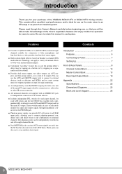
...Appendix 22 Specifications 22 Dimensional Diagrams 25 Block and Level Diagram 26 6 MG32/14FX, MG24/14FX The phantom power can also serve as part of the YAMAHA MG32/14FX or MG24/14FX mixing console. Contents Introduction 6 Features 6 Connecting to any... combination of 14 outputs. Introduction Thank you for connection to both microphones and line-level devices. These switches make it easy to selectively monitor the input and output signals through this manual...
...Appendix 22 Specifications 22 Dimensional Diagrams 25 Block and Level Diagram 26 6 MG32/14FX, MG24/14FX The phantom power can also serve as part of the YAMAHA MG32/14FX or MG24/14FX mixing console. Contents Introduction 6 Features 6 Connecting to any... combination of 14 outputs. Introduction Thank you for connection to both microphones and line-level devices. These switches make it easy to selectively monitor the input and output signals through this manual...
MG32/14FX MG24/14FX Owners Manual
Page 8
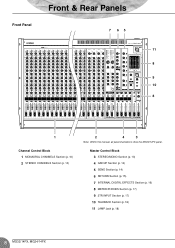
Master Control Block 3 STEREO/MONO Section (p. 13) 4 GROUP Section (p. 14) 5 SEND Section (p. 14) 6 RETURN Section (p. 15) 7 INTERNAL DIGITAL EFFECTS Section (p. 16) 8 METER/PHONES Section (p. 17) 9 2TR INPUT Section (p. 17) 10 TALKBACK Section (p. 18) 11 LAMP Jack (p. 18) 8 MG32/14FX, MG24/14FX Front Panel Front & Rear Panels 7 65 11 8 9 10 8 1 Channel Control Block 1 MONAURAL CHANNELS Section (p. 10) 2 STEREO CHANNELS Section (p. 10) 2 4 3 Note: Within this manual, all panel illustrations show the MG32/14FX panel.
Master Control Block 3 STEREO/MONO Section (p. 13) 4 GROUP Section (p. 14) 5 SEND Section (p. 14) 6 RETURN Section (p. 15) 7 INTERNAL DIGITAL EFFECTS Section (p. 16) 8 METER/PHONES Section (p. 17) 9 2TR INPUT Section (p. 17) 10 TALKBACK Section (p. 18) 11 LAMP Jack (p. 18) 8 MG32/14FX, MG24/14FX Front Panel Front & Rear Panels 7 65 11 8 9 10 8 1 Channel Control Block 1 MONAURAL CHANNELS Section (p. 10) 2 STEREO CHANNELS Section (p. 10) 2 4 3 Note: Within this manual, all panel illustrations show the MG32/14FX panel.

MG32/14FX MG24/14FX Owners Manual
Page 9
Rear Panel Front & Rear Panels 13 Rear Input/Output Block 12 CHANNEL I/O Section (p. 19) 13 MASTER I/O Section (p. 20) 12 Note: Within this manual, all panel illustrations show the MG32/14FX panel. 9 MG32/14FX, MG24/14FX
Rear Panel Front & Rear Panels 13 Rear Input/Output Block 12 CHANNEL I/O Section (p. 19) 13 MASTER I/O Section (p. 20) 12 Note: Within this manual, all panel illustrations show the MG32/14FX panel. 9 MG32/14FX, MG24/14FX
MG32/14FX MG24/14FX Owners Manual
Page 22
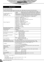
Variation 3 Stereo Input Channel Equalization: Max. Appendix Specifications ■ General Specifications Frequency Characteristics (Master Output) Total Harmonic Distortion (Master Output) Hum and Noise (20 Hz - 20 kHz) 1 Input GAIN = Maximum Input PAD = OFF Input sensitivity = -60 dBu Maximum Voltage Gain 2 Monaural/Stereo Input Gain Control Monaural High Pass Filter Channel Input PAD Crosstalk (1 kHz) Monaural Input Channel Equalization: Max. Variation 3 Internal Digital Effects MONO Low Pass Filter Monaural/Stereo Input Peak Indicator Monaural/Stereo Input Signal Indicator ...
Variation 3 Stereo Input Channel Equalization: Max. Appendix Specifications ■ General Specifications Frequency Characteristics (Master Output) Total Harmonic Distortion (Master Output) Hum and Noise (20 Hz - 20 kHz) 1 Input GAIN = Maximum Input PAD = OFF Input sensitivity = -60 dBu Maximum Voltage Gain 2 Monaural/Stereo Input Gain Control Monaural High Pass Filter Channel Input PAD Crosstalk (1 kHz) Monaural Input Channel Equalization: Max. Variation 3 Internal Digital Effects MONO Low Pass Filter Monaural/Stereo Input Peak Indicator Monaural/Stereo Input Signal Indicator ...
MG32/14FX MG24/14FX Owners Manual
Page 23
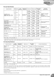
...20 dBu (7.75 V) (impedance balanced [T: hot; European Models Purchaser/User Information specified in every locale, please check with your Yamaha dealer. Appendix ■ Input Specifications Input Connector PAD Gain Input Impedance Appropriate Impedance Sensitivity 1 Rated Level Max. S: ground])...jack Where 0 dBu = 0.775 V and 0 dBV= 1 V Specifications and descriptions in this owner's manual are for information purposes only. Before Clipping Connector Specifications CH INPUT (A, B) (MG32/14FX: CHs 1 to 24) (MG24/14FX: CHs 1 to 16) 0 -60 26 0 -16 26 3...
...20 dBu (7.75 V) (impedance balanced [T: hot; European Models Purchaser/User Information specified in every locale, please check with your Yamaha dealer. Appendix ■ Input Specifications Input Connector PAD Gain Input Impedance Appropriate Impedance Sensitivity 1 Rated Level Max. S: ground])...jack Where 0 dBu = 0.775 V and 0 dBV= 1 V Specifications and descriptions in this owner's manual are for information purposes only. Before Clipping Connector Specifications CH INPUT (A, B) (MG32/14FX: CHs 1 to 24) (MG24/14FX: CHs 1 to 16) 0 -60 26 0 -16 26 3...

MG32/14FX MG24/14FX Owners Manual
Page 28
... & Digital Musical Instrument Division Nakazawa-cho 10-1, Naka-ku, Hamamatsu, Japan 430-8650 Tel: +81-53-460-2441 Yamaha Manual Library http://www.yamaha.co.jp/manual/ U.R.G., Pro Audio & Digital Musical Instrument Division, Yamaha Corporation © 2003 Yamaha Corporation WA66540 004CRZCx.x-xxE0 Printed in Zürich Seefeldstrasse 94, 8008 Zürich, Switzerland Tel: 01-383 3990...
... & Digital Musical Instrument Division Nakazawa-cho 10-1, Naka-ku, Hamamatsu, Japan 430-8650 Tel: +81-53-460-2441 Yamaha Manual Library http://www.yamaha.co.jp/manual/ U.R.G., Pro Audio & Digital Musical Instrument Division, Yamaha Corporation © 2003 Yamaha Corporation WA66540 004CRZCx.x-xxE0 Printed in Zürich Seefeldstrasse 94, 8008 Zürich, Switzerland Tel: 01-383 3990...

